

Accel TEMPEST 3302 User Manual

T empest® Hot Air Drying System
Installation Instructions
Ryobi 3302
Itek 3985
A.B. Dick 9985
X88-43
01/2001
Rev-B
2740

GENERAL INFORMATION
ATTENTION
TEMPEST® DRYER
OWNER!
Accel Graphic Systems provides parts and service through its
authorized distributors and dealers. Therefore, all requests for
parts and service should be directed to your local dealer.
The philosophy of Accel Graphic Systems is to continually improve
all of its products. Written notices of changes and improvements
are sent to Accel Graphic Systems' Dealers.
If the operating characteristics or the appearance of your product
differs from those described in this manual, please contact your
local Accel Graphic Systems Dealer for updated information and
assistance.
Always update your equipment when improvements are made
available, especially those related to safety.
YOUR AUTHORIZED TEMPEST® DEALER IS:
TECHNICAL
ASSISTANCE
2
THE SERIAL NUMBER OF YOUR
TEMPEST® HOT AIR DRYING SYSTEM IS:
CONTROL BOX
FAN UNIT
For technical assistance during the installation, please contact:
ACCEL GRAPHIC SYSTEMS
11103 INDIAN TRAIL
Dallas, TX 75229
PHONE (972) 484-6808
FAX (800) 365-6510
E-MAIL accel@dallas.net
WEB SITE www. accelgraphicsystems.com

GENERAL INFORMATION
ELECTRICAL
REQUIREMENTS
IMPORTANT
INFORMATION
SAFETY
INFORMATION
220 VAC 50/60 HZ
20 AMP DEDICATED LINE
NEMA L620R RECEPTACLE
The use of heat to accelerate drying may require more frequent
lubrication and/or use of a high temperature lubricant in the delivery of
the press. Please consult your press manufacturer for specific recommendations.
The Tempest® Dryer contains high voltage and hot surfaces. Never
attempt to service or work on the unit unless the power is shut off and
the unit is cool.
Visually inspect the thermistors (Barn housed-shaped objects arranged in a honeycombed pattern on the underside of the unit) weekly.
If a thermistor is damaged or cracked, do not operate the dryer. Contact
Accel immediately for a replacement part.
TERMINOLOGY
The fans should be turned on and set at the lowest speed ("0" on the
dial) when running spray powder only without heat. This prevents
spray powder from accumulating in the thermistors and housings.
OPS = Operator's Side
NOPS= Non Operator's Side
3

GENERAL INFORMATION
HOT AIR
VS INFRARED
WHAT MAKES
TEMPEST
®
WORK
Although the technology behind the Tempest® dryer was significant
enough to be awarded the GATF Intertech Award, it is by no means
new. In fact, thermistors have been in use for many years. They
were originally used in motors and other devices as a heat
controller and later used in refrigeration to turn compressors on and
off. It is only in the last 10 years or so that thermistors have been
used as a heater.
Heat is generated by the thermistor because of the difficulty of
electricity travelling through it when it is a conductor. The thermistor
acts as a conductor until it reaches its set temperature and then it
becomes a resistor. A thermistor is basically a coated
semiconductor designed to switch from a conductor to a resistor at
an established temperature.
When a current is applied to the thermistor it initially uses a large
amount of electricity and heats up very quickly until it reaches its
maximum set temperature. At this point it should not use any more
electricity. However, air that is passed through the holes in the
thermistor causes it to cool. This activates the thermistor to start
using more power again so that can get back to its set temperature.
The thermistor is constantly regenerating itself to stay at a constant
temperature. This process is called autostabilization.
4
Thermistors are also the key element that makes the Tempest
dryer safe. Because the set temperature of the thermistor is lower
than the flash point of paper, you can place even the most easily
burned substrate (such as tissue paper) on top of the thermistor
element without causing a fire. The tissue won't even char, let
alone ignite. If you were to do the same with an IR element, a fire
could start in a matter of seconds. This is particularly important if a
jam occurs in the delivery.
The objective of any drying system is to raise the pile temperature
to accelerate the drying of the ink. However, heating the paper too
much can aggravate problems such as blocking, setoff, mottle, loss
of gloss, and loss of halftone definition. Too much heat can also
cause the paper to shrink which can cause register problems in
multiple pass work. The Tempest® dryer can keep the pile at a
lower temperature than IR and still effectively set the ink film.
®

GENERAL INFORMATION
IR dryers use very high temperatures and a fixed amount of electricity.
One of the drawbacks of using a very hot heat source is that heat wants
to travel from a very high temperature to a very low temperature. In
other words, the heat generated from an IR dryer will travel to the press
wall and attempt to increase its temperature because it is cooler than
the heat produced by the IR dryer. Because the thermistors used in the
Tempest® dryer use lower temperatures, the heated air has had time
to cool by the time it reaches the wall of the press, reducing the chance
of premature wear to press parts.
HOW DRYING IS
ACCOMPLISHED
WITH TEMPEST
KEY FACTORS
TO REMEMBER
ABOUT DRYERS
FOR SMALL
OFFSET
PRESSES.
Tempest® "sets" the surface of the ink to prevent set-off from one sheet
to another and to minimize the use of powder.
®
Tempest® accelerates the final drying of oil based inks by raising the
temperature of the delivery stack.
Do not expect a dryer to "instantly" dry the ink. Only UV inks and
coating dry instantly. The technology and hazards of such systems
make them cost prohibitive on small offset presses.
Some jobs may require spray powder. Because dryers for small offset
presses do not dry ink instantly, powder will be required from time to
time. However, you should expect to see a significant decrease in the
amount of powder needed on a regular basis.
Drying time is dependent upon press speed, paper stock, ink coverage,
type of ink, etc.
Do not expect a dryer to accelerate the drying of rubber based inks.
These inks dry by absorption into the stock, and heat does not
accelerate this process.
5
6

1
2
INSTALLATION
DISCONNECT THE POWER T O THE PRESS BEFORE
BEGINNING INSTALLATION.
Remove the two large side co vers ov er the main frame work of the
press (one at OPS and one at NOPS) and the NOPS cover at the
delivery end of the press.
For an easier installation, you may also want to remove the two
guards on the delivery end of the press.
NOTE: Do not cut the hose if the press is equipped with an
Airtech sprayer .
3
Cut the sprayer hose about halfway between the hopper and the
spray bar. A new hose will be attached to the spra y mechanism.
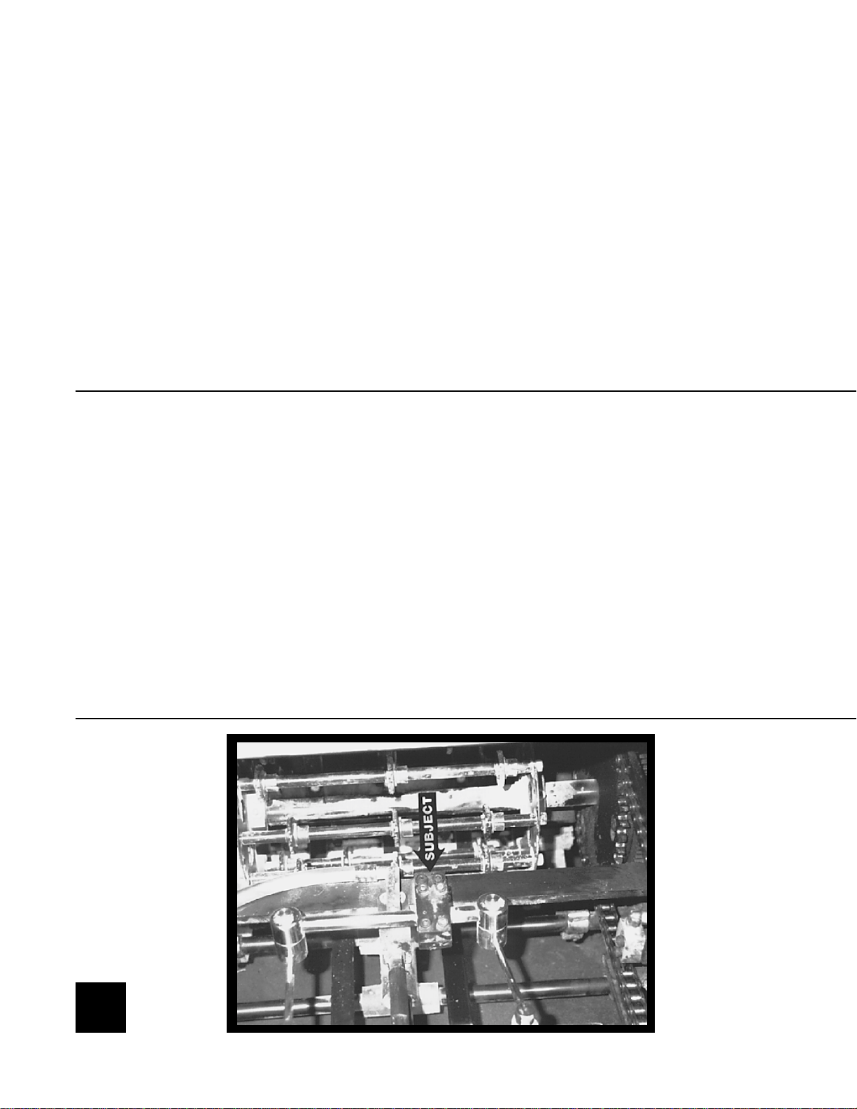
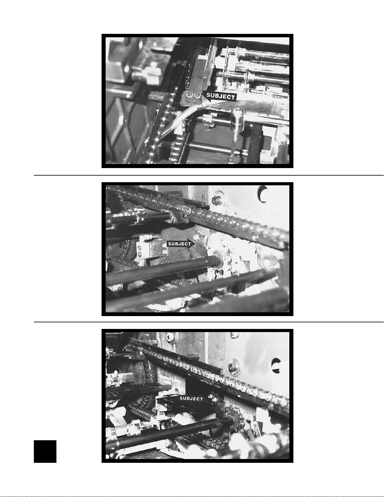
NOTE: Do not remove the spray bar if the press is equipped
with an Airtech sprayer .
Remove the spray bar by removing the two bolts holding the
bracket (subject arrow). Also remove the clip holding the spray
hose (subject arrow, picture on following page).
7
8

4
INSTALLATION
Remove the chain guide (subject arrow) at the OPS & NOPS sides
of the press.
5
Install the mounting bracket and new chain guide using M5 X 16MM
cap head bolts and lock washers (subject arrow) as sho wn at the
OPS & NOPS. Leave the bolts loose so the position of the dryer can
be moved up and down. The bolts thread into the same holes that
held the original chain guides.
9
10

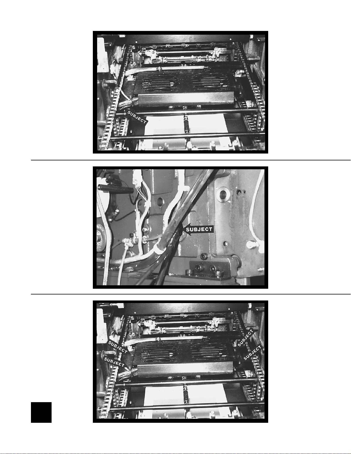
6
INSTALLATION
Note: If the press is equipped with an Airtech sprayer , you must
remove the spray bar from the dryer before installing it in the
press. To remove the spray bar from the dryer, remove the three
screws on the top of the dryer .
Set the dryer on the brackets with the cable exiting at the NOPS.
Run the cable under the mounting bracket (subject arrow, left
picture) and through the large hole in the side frame (subject arrow ,
lower picture) directly under the mounting bracket.
7
Secure the dryer to the brackets (f our places) using the short button
head bolts, washer , and flanged nut (subject arrows). Leav e the bolt
loose so the dryer can be moved front to back.
11
12

8
9
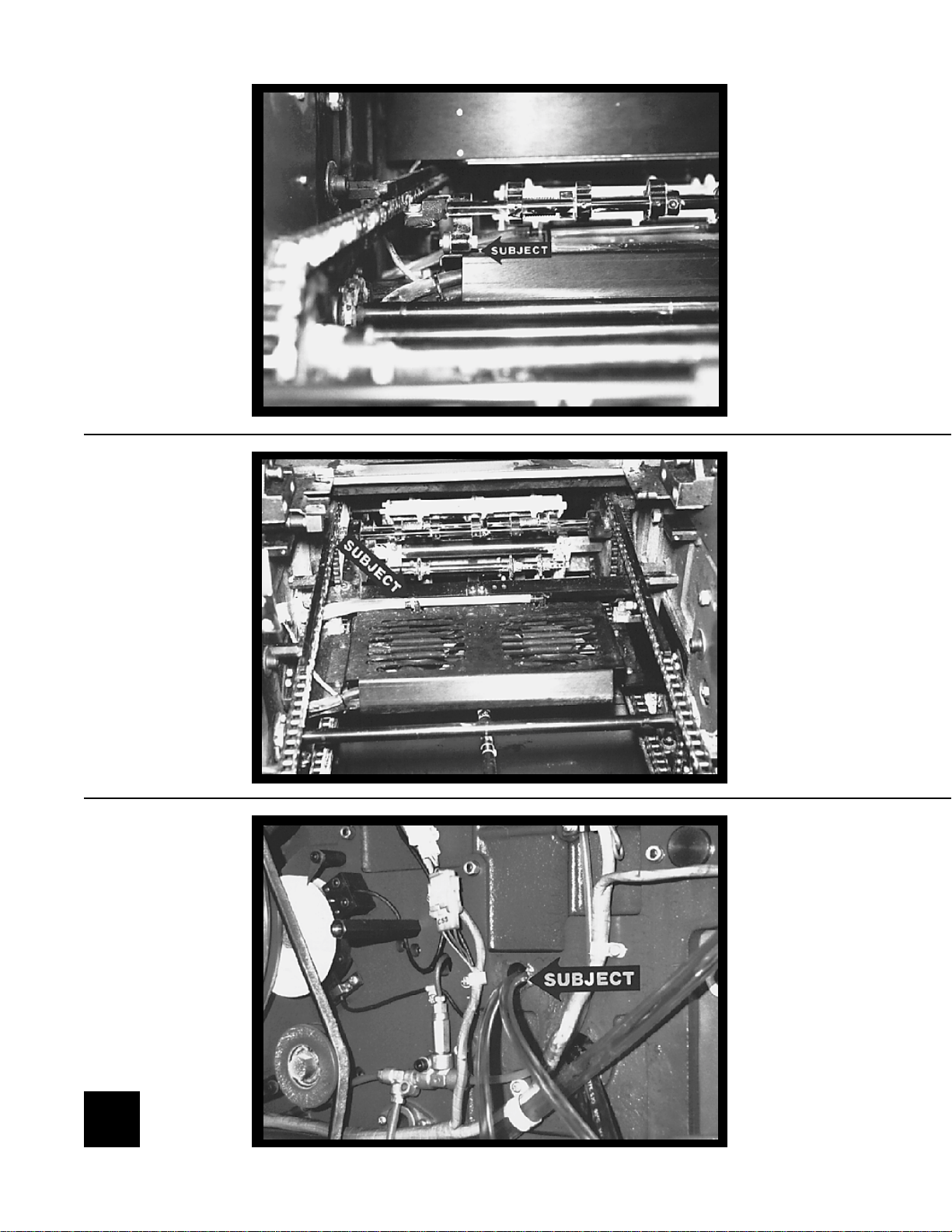
INSTALLATION
Position the dryer so it clears the gripper opening mechanism on all
three delivery gripper bars. The arm must clear both the top and
bottom of the dryer. The photo shows the arm clearing the top of the
dryer (subject arrow). After positioning the dryer , tighten the bolts
holding the mounting brackets to the press frame and the bolts
holding the dryer to the mounting brackets.
NOTE: If the press is equipped with an Airtech sprayer, proceed to step 11.
Attach two hoses to the elbows in the sprayer housing (subject
arrow , upper picture) and run the hose through the hole in the side
frame (subject arrow, lower picture ). Note how the hoses are tied
together with a zip tie in the upper picture on the left hand side.
13
 Loading...