

Acare AH-M1 Instruction manual

Handheld Pulse Oximeter
Model: AH-M1
Instruction Manual
Issued Date: Jul. 12, 2011
Ver.1.0

Handheld pulse oximeter instruction manual
Product Information
z Product Model: AH-M1
z Product Name: Handheld pulse oximeter
z Manufacturer: Acare Technology Co., Ltd.
z After Service Contact Information:
Address: 6F.-6, No.5, Wuquan 1st Rd., Xinzhuang Dist.,
New Taipei City 242, Taiwan
TEL : +886-2-2298-8170
FAX : +886-2-2298-8560
Email: service@acaretech.com
Revision History
This manual has a revision number. This revision number
changes whenever the manual is updated due to software or
technical specification change. Contents of this manual are
subject to change without prior notice.
z Document No.: P2000040-1
z Revision number: 1.0
z Release time: 2011-07
Copyright © 2011 Acare Technology Co., Ltd. All rights
reserved.
I

Handheld pulse oximeter instruction manual
CE mark
EC Representative Name:
MEDIPRO
Villapark Business Park, Av Quitapesares 8, Building 8,
Villaviciosa de Odon (Madrid) 28670, Spain
Statement
The manufacturer, Acare, holds the copyright to this
manual, and is entitled to treat it as a proprietary file. This
manual is only to be used for supporting the operation,
maintenance and service of the AH-M1 product, and it
cannot be resold or republished by any other party.
This manual contains exclusive information protected by
copyright laws and we, Acare, reserve its copyright. No parts
of this manual shall be photocopied, Xeroxed or translated
into other languages without written approval from the
manufacturer.
The contents of this manual are subject to amendment
without notification.
II

Handheld pulse oximeter instruction manual
Manufacturer's Responsibility
The manufacturer will be responsible for the safety,
reliability and performance of the instrument under the
following circumstances only:
z All installation, expansion, readjustment, renovation or
repairs of the instrument are conducted by personnel
certified by the manufacturer.
z The storage conditions, operating conditions and
electrical status of the instrument conform to the
product specification.
z The instrument is used in accordance with the user
manual.
About this manual
This manual contains the instructions necessary to
operate the product safely and in accordance with its
function and intended use. Observance of this manual is a
prerequisite for proper product performance and correct
operation of the product, and ensures patient and operator
safety.
III

Handheld pulse oximeter instruction manual
This manual is based on the maximum potential
configuration of the product, and therefore some contents
may not apply to your device. If you have any questions,
please contact us.
This manual is an integral part of the product. It should
always be kept close to the equipment so that it can be
referred to when needed.
All illustrations in this manual serve only as examples.
They may not necessarily reflect the setup or data displayed
on your product.
Key:
z Bold Italic text is used in this manual to quote the
referenced chapter or sections.
z 【】is used to signify text as it appears on the
product screen.
z → is used to indicate operational procedures.
IV

Handheld pulse oximeter instruction manual
0
)
Warning: Indicates a potential hazard or unsafe
practice that, if not avoided, will result in death
or serious injury.
Caution: Indicates a potential hazard or unsafe
practice that, if not avoided, could result in minor
personal injury or product/property damage.
Note: Provides application tips or other useful
information to ensure that you get the most from
your product.
V

Contents
Chapter 1 General Introduction........................................1
1.1 Intended Use...............................................................1
1.2 Main Unit...................................................................2
1.2.1 Front View............................................................2
1.2.2 Rear View.............................................................5
1.2.3 Side View..............................................................6
1.3 Display Views.............................................................7
1.3.1 Large Numeric Display Mode...............................7
1.3.2 SpO2 Waveform Display Mode............................9
Chapter 2 Safety.................................................................1
2.1 Safety Information......................................................1
2.2 Explanation of Symbols..............................................3
Chapter 3 Basic Operat ions...............................................1
3.1 Unpacking and Checking............................................1
3.2 Getting Started............................................................2
3.3 Starting the oximeter...................................................3
3.4 General Setup.............................................................3
3.4.1 Beep Volume Setup...............................................3
3.4.2 Key Volume Setup................................................4
3.4.3 Adjust the Screen Brightness................................4
3.4.4 Scan Speed Setup..................................................4
3.5 Date and Time Setup...................................................5

3.6 Selecting the Work Mode............................................5
3.6.1 Continuous Monitoring Mode...............................6
3.6.2 Spot-checking Mode.............................................7
3.7 Selecting Patient Type.................................................8
3.8 Entering/Exiting the Demo Mode...............................8
3.9 Changing the Language..............................................9
3.10 Checking the Version ...............................................9
3.11 Restoring the Factory Configuration.........................9
3.12 Shutting off the Oximeter.......................................10
Chapter 4 Alarm.................................................................1
4.1 Alarm Categories........................................................1
4.2 Alarm Levels..............................................................2
4.3 Alarm Indicators.........................................................3
4.3.1 Alarm tone............................................................4
4.3.2 Alarm Lamp .........................................................5
4.3.3 Alarm Message.....................................................6
4.3.4 Flashing Numeric..................................................6
4.4 Alarm Status Symbol..................................................6
4.5 Alarm Tone Configuration..........................................7
4.5.1 Setting the minimum Alarm Volume.....................7
4.5.2 Changing the Alarm Volume.................................7
4.6 Pausing the Alarm Tones.............................................7
4.7 Shutting off the Alarm Volume...................................8

4.8 When an Alarm Occurs...............................................9
Chapter 5 Measuring SpO2................................................1
5.1 Introduction................................................................1
5.2 Safety Information......................................................2
5.3 Monitoring Procedure.................................................4
5.4 SpO2 Display..............................................................5
5.5 PR Display..................................................................5
5.6 SpO2 Alarm Setup......................................................6
5.6.1 Switching SpO2 Alarm On/Off.............................6
5.6.2 Setting the Alarm Level........................................6
5.6.3 Adjusting the Alarm Limit....................................6
5.6.4 Altering the Desaturation Limit.............................7
5.7 PR Alarm Setup..........................................................7
5.7.1 Switching PR Alarm On/Off.................................7
5.7.2 Setting the Alarm Level........................................7
5.7.3 Adjusting the Alarm Limit....................................8
Chapter 6 Reviewing...........................................................1
6.1 Introduction................................................................1
6.2 Reviewing Screen.......................................................1
6.3 Reviewing Setup.........................................................2
Chapter 7 Battery...............................................................1
7.1 Introduction................................................................1
7.2 Installing Batteries......................................................3

7.2.1 Opening the Battery Door.....................................3
7.2.2 Installing the Alkaline Battery...............................4
7.2.3 Installing the Lithium-Ion Battery.........................5
7.3 Charging Lithium Ion Battery.....................................6
7.4 Optimizing Battery Performance................................7
7.5 Checking the Lithium-Ion Battery..............................8
7.6 Disposing of the Batteries...........................................9
Chapter 8 Maintenance and Cleaning...............................1
8.1 Introduction................................................................1
8.2 Annual Safety Checks.................................................2
8.3 Cleaning the Oximeter................................................4
8.4 Cleaning SpO2 Sensor................................................5
8.5 Disposal......................................................................6
Chapter 9 Accessories.........................................................1
Appendix A Product Specifications...................................1
A.1 Safety Specifications..................................................1
A.2 Physical Specifications...............................................1
A.3 Environmental Specifications.....................................2
A.4 Charging Specifications.............................................2
A.4.1 AC-DC Adapter (Optional)...................................2
A.4.2 Battery Specification............................................2
A.5 Hardware Specifications............................................4

A.5.1 Display.................................................................4
A.5.2 Indicating LED.....................................................4
A.5.3 Audio Indicating...................................................5
A.5.4 Buttons.................................................................5
A.5.5 Sensors.................................................................6
A.6 Data Storage...............................................................6
A.7 Measurement Specifications.......................................7
A.7.1 Digital SpO2........................................................7
A.7.2 Nellcor SpO2 .......................................................8
A.7.3 Alarm limit specifications....................................8
Appendix B EMC.............................................................10
Appendix C Factory Defaults..........................................15
C.1 Alarm Setup.............................................................15
C.2 System Setup............................................................15
C.3 SpO2 Setup..............................................................16
C.4 Trend Setup..............................................................16
Appendix D Alarm Message............................................17
D.1 Physiological alarm..................................................17
D.2 Technical alarm........................................................18

Chapter 1 General Introduction
1.1 Intended Use
The AH-M1 handheld pulse oximeter is intended for
continuously monitoring or spot checking peripheral oxygen
saturation (SpO2) and pulse rate (PR) for adult, pediatric or
neonatal patients.
This device can be used in institutions or units with
health care capability. This includes outpatient departments,
emergency rooms and departments of internal medicine in
hospitals, ordinary departments in clinics, nursing hospitals
and community medical institutions. It may also be used in
the home.
1.2 Main Unit
1.2.1 Front View
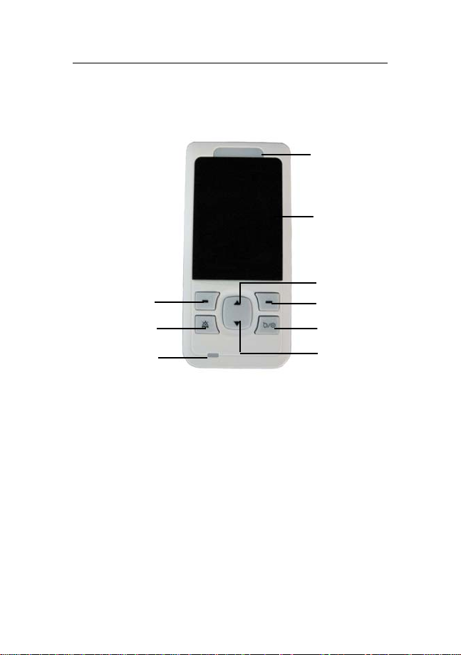
3
5
1
2
7
4
6
9
Fig 1-1 Front view of the oximeter
8
1 Alarm indication lamp
When an alarm occurs, this lamp will light up as defined
below:
z High level alarm: the lamp quickly flashes red.
z Medium level alarm: the lamp slowly flashes yel-
low.
z Low level alarm: the lamp lights yellow without

flashing.
2 Display screen
3 Left button
Press this button to:
z Enter the main menu under the monitoring screen.
z Select the highlighted menu item under the menu
screen.
4 Right button
Press this button to:
z Switch the screen display between large numeric
mode and SpO
monitoring screen.
z Exit current menu under the menu screen.
5 Alarm pause button
Pressing this button:
z Will not work when the alarm volume is off.
z Can pause the alarm for 120 seconds when the
alarm volume is on.
z Changes the alarm message to prompt message
when “Sensor off” alarm is activated.
z Note: the alarm can-not be permanently switched
waveform mode under the
2

off.
6 Power button
After the batteries are installed:
z Press this button to turn on the oximeter.
z Press and hold it for 2 seconds to turn the oximeter
off.
7 Up button
Press this button to:
z Raise the volume of the heart beat displayed
z Move the cursor upwards or increase the value of a
selected menu item under the menu screen.
8 Down button
Press this button to:
z Lower the volume of the heart beat displayed
z Move the cursor downwards or decrease the value
of a selected menu item.
9 Battery charging indicating lamp
z Lights orange when the battery is being charged.
z Will show no light when the battery is fully charged
or not being charged.

1.2.2 Rear View
Fig 1-2 Rear view of the oximeter
1. Speaker
2. Battery door
1
2
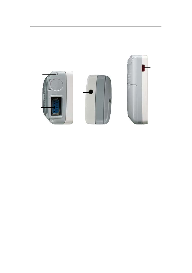
1.2.3 Side View
Topside: Downside: Leftside:
2
3
1
Fig 1-3 Side view of the oximeter
1. SpO
2. Cord hold
3. Power supply connector
4. Infrared port
probe connector
2
Used to connect the charger stand.
A port through which a personal computer can
communicate with the product, to export data in real
time.
4
1.3 Display Views
This device features an automatic display rotation
(gravity activated), which allows vertical and horizontal
positioning of the screen, to maximize space utilization and
visibility.
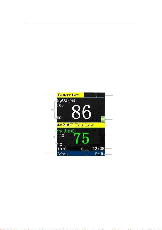
1.3.1 Large Numeric Display Mode
6
5
4
3
2
1
Fig 1-4 Big numerics display mode
120
s
11
7
8
9
10
1. Menu: Directly after startup, 【Menu】 shown here, is
the function controlled by the left hand button. When

appropriate, press the left button to enter 【Menu】.
2. Patient ID No.: When 【Continuous】 is selected for
work mode, the patient ID is set at 0 at all times; when
【 Spot-Check 】 is selected, the ID will display a
number between 1 and 99.
3. PR parameter area: Current pulse rate (PR) value and its
high and low alarm limits are displayed in this area.
4. Physiological alarm area: Current physiological alarm
information is displayed in this area.
5. SpO
6. Technical alarm and prompt information area: Current
7. Alarm status area: Alarm status symbols and alarm
8. Pleth bar: Pulse intensity is indicated by the number of
9. System time: Current time is shown in the area.
parameter area: Current SpO2 value and its high
2
and low alarm limits are displayed in this area.
technical alarm and prompt information is shown in this
area.
pause time are displayed in this area.
stacked blocks visible.
10. Shift: Directly after startup, 【Shift】shown here is the
function controlled by the right hand button. Press the
right hand button to shift between different display

modes.
11. Battery symbol: This symbol indicates the remaining
quantity of electrical charge in the batteries.
1.3.2 SpO2 Waveform Display Mode
2
1
Fig 1-5 SpO2 waveform display mode
1. SpO
waveform area: The waveform shown in this area
2
illustrates the current SpO
volume curve of the patient
2
3
being monitored.
2. SpO
parameter area: Current SpO2 value and its upper
2
and lower alarm limits are displayed in this area.
3. PR parameter area: Current PR value and its upper and
lower alarm limits are displayed in this area.

Handheld pulse oximeter user ’s manual
Chapter 2 Safety
2.1 Safety Information
0
Warning:
Explosion hazard: Do not use the oximeter in the
presence of flammable anesthetics mixed with air,
oxygen, or hydrogen.
Do not use the product in the presence of high
power appliances such as high voltage cables, X-ray
machines, ultrasound equipment or a defibrillator.
Keep the oximeter away from dust, vibration,
corrosive substances, explosive materials, high
temperature and moisture.
The device is not designed for use in a sterile field
The oximeter should be handled with care so as to
avoid it getting knocked or falling.
1

Handheld pulse oximeter user ’s manual
Warning:
0
Do not use this device during defibrillation.
When the device is in use, ensure that the batteries
have sufficient charge remaining; otherwise startup abnormalities may occur or the measurement
data may be inaccurate.
Patients must not wear nail varnish while using the
pulse oxi meter as this wi ll lea d to unreli able SpO
measurements.
Measurements and pulse signals can be affected by
certain environmental conditions, errors in
applying the sensor, and certain patient conditions.
See the appropriate sections of this manual for
specific safety information.
The use of accessories, sensors, and cables other
than those specified may result in increased
emission, low anti-disturbance and/or may lead to
the oximeter producing invalid readings. It is
advisable to check the oximeter at least once a
month.
2
2
Handheld pulse oximeter user ’s manual
Caution: In order to obtain accurate results, the
oximeter should be used in a quiet and comfortable
environment.
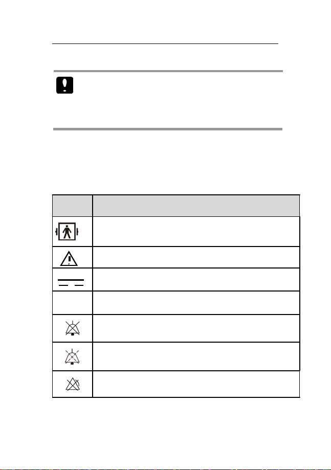
2.2 Explanation of Symbols
Symbol Symbol Note
Type BF applied part, defibrillation protected
Attention: Consult accompanying documents (this manual).
Direct Current(DC)
IPX1
Degree of protection against ingress of liquid
Alarm volume off
Alarm volume pause
parameter alarm off
3
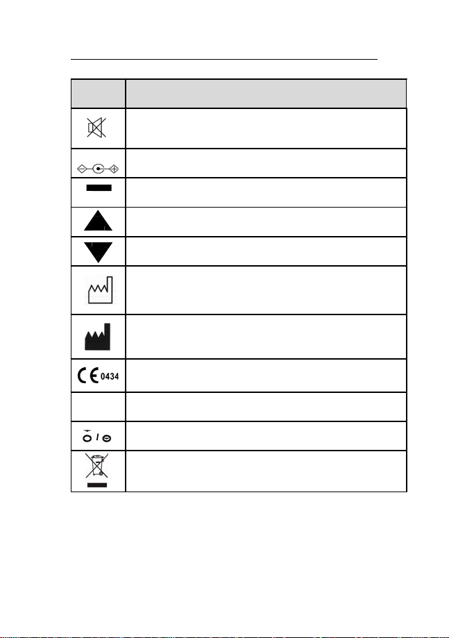
Handheld pulse oximeter user ’s manual
Symbol Symbol Note
SN Serial number
Beep volume off
Power supply connector
Left/right button
Up button
Down button
Date of manufacture
Manufacturer
CE mark
Power button
Symbol for the marking of electrical and electronics devices
according to Directive 2002/96/EC.
4

Handheld pulse oximeter user ’s manual
Chapter 3 Basic Operations
3.1 Unpacking and Checking
Open the package. Take out the oximeter and its
accessories. The following parts are provided in the package:
Parts Standard Optional Quantity
SpO2 probes
(DB9 plugs)
User’s manual √ this manual
Lithium battery √ 1
AC-DC adapter √ 1
Battery charger stand √ 1
Protective cover √ 1
Clip with lanyard √ 1
QuickStart √ 1
CDROM √ 1
Check list √ 1
Alkaline battery √ 3
√ 1
1

Handheld pulse oximeter user ’s manual
3.2 Getting Started
1. Before using the oximeter to take measurements for the
first time, carry out the following checks on the oximeter
and all connected modules:
——Check for any mechanical damage;
——Check for correct connection between of all the
external cables and accessories.
2. Insert batteries into the battery compartment. Make sure
that the battery has sufficient power. When using
rechargeable batteries for the first time, you must charge
them,first, following the instructions given in the Battery
chapter.
0
Warning:
If the oximeter is mechanically damaged, or if it is
not working properly, do not use it on a patie nt for
any monitoring procedure. Contact your service
personnel.
To avoid the risk of explosions, do not use the
oximeter in the presence of flammable
anesthetics, vapors or liquids.
2
Handheld pulse oximeter user ’s manual
3.3 Starting the oximeter
Press the button to turn on the oximeter. The alarm
indication lamp should flash, and then stop. The system
should give a beep and enter the main screen. After starting
the oximeter you can change the settings for more
convenient use, as shown in section 3.4.
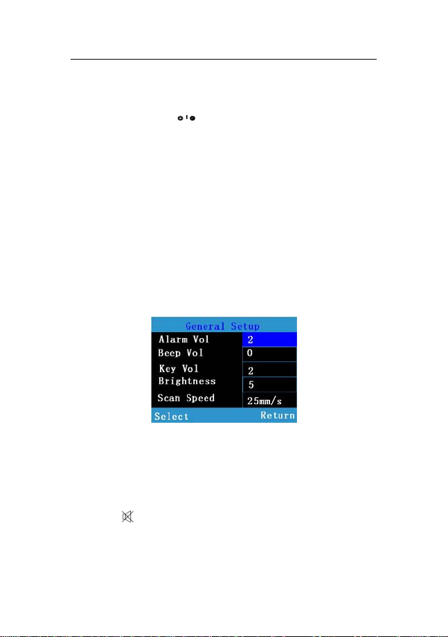
3.4 General Setup
Press the Left button to enter 【 Menu 】 , then
select 【General Setup 】 to enter the general setup menu
shown as follows. You can set parameters for the following
functions: .
Fig 3-1 General setup window
3.4.1 Beep Volume Setup
Press the Left button to select the item, then adjust its
value using the Up or Down button. You can select from 0 to
4. A sign will be shown at the bottom of the monitoring
3
 Loading...