


Operating Manual
A100
1

© 2013 venotec GmbH
GmbH
Am Nordkreuz 36
26180 Rastede
Deutschland
www.venotec.de
Any claims against venotec in relation to the products described in this manual
shall be handled exclusively as per the guarantee conditions of the manufacturer.
The product specifications may deviate from the information in this manual due to
technical improvements and innovations. Abyzz, BOOSTMODE and venotec are
registered trademarks.
Valid as of: 04.02.2014
2

Table of contens
Page
Preface
5
Scope of delivery
6
Function description
7
Abyzz peripheral devices and connection options
8
Warnings
9
Proper use and general information
10
Installation of driver
11
Installation of pump
12
Commissioning
13
Run in phase
13
Description of control elements
14
Operation
15
Maintenance
18
Guarantee
23
Technical changes
24
Troubleshooting
24
Disposal
25
Technical data
25
Materials
26
Appendix
27ff
Test report
29
3

List of figures
Page
Fig. 1a/b
Connector view of driver
12
Fig. 2:
Bearing straight from factory and following run in phase
14
Fig. 3:
Overview of messages
16
Fig. 4:
Abyzz boost mode
17
Fig. 5:
Pump with pump head
18
Fig. 6a/b:
Disassembly of pump head
19
Fig. 7:
Removing impeller group
20
Fig. 8:
O-ring position and assembly
21
Fig. 9:
Assembly of pump head
22
Fig. 10:
Flow charts
27
Fig. 11
Dimension of pump A100
28
4

Preface
Thank you for buying an Abyzz® pump! By buying this powerful product, you have
acquired a highly efficient, fully variable pump that was developed and
manufactured in Germany to meet the most stringent quality and performance
requirements. This manual aims to help you to start using the product and to make
the required settings.
In order to reap the benefits of this product for as long as possible, please read
this manual carefully and observe our recommendations.
Should the quality of the product not meet your expectations, please contact the
dealer who sold you the pump or contact us directly. We recommend that you use
the provided form to register your product with us so that we can provide you with
the best possible service. Please make sure that the serial number on your
product remains legible and be ready to provide us with this number if asked.
Legend
This symbol indicates particularly important information.
5

Scope of delivery
1 Abyzz A100 pump with 2m cable including pump stand
1 Abyzz A100 driver
1 Abyzz connecting cable (for Abyzz peripheral devices)
1 Abyzz mains cable
1 Registration form
1 Owners manual
6

Function description
The core component of the Abyzz® A100 pump is a three-phase synchronous
motor driven by sine waves. The high efficiency of the motor combined with the
low motor voltage makes it ideal for energy saving and safety pump appliances.
Integrated bearing flushing provides optimum protection against calcination and
ensures low-maintenance operations.
The materials used are designed to have a long lifetime and meet the highest
requirements and quality standards. Our products are developed and
manufactured in Germany. Thus, they deserve this label:
"Made in Germany"
The electronic control unit has optimum operating properties. In particular, these
properties include the following:
- Variable speed range (0 - 100%)
- Programmable control unit including Abyzz BOOSTMODE
®
- Dry run protection
- Soft startup
- Bus-enabled interface*
- Lockable plug contacts
- Temperature protection
- Overcurrent protection
- Current limitation
- Low-noise operation
- Long lifetime
- Minimal power loss (especially low loss of heat into water).
7

Abyzz peripheral devices and connection options
The Abyzz connecting cable required for the connection of peripheral devices
forms part of the scope of delivery of the pump*. If you do not use any peripheral
devices, please secure both connections using the provided caps to prevent
corrosion and the penetration of dust.
Abyzz control system (ACS):
The ACS allows you to control several (currently up to 8) Abyzz pumps. You can
program in different profiles to generate waves, tides, or other flow patterns, for
example.
In addition, the ACS allows you to centrally operate and monitor all bus-enabled
Abyzz products. For example, operating data, alarms, temperatures, and so on are
displayed centrally on the ACS display.
There are two D-sub connectors on the bottom of the Abyzz A200 pump driver for
this purpose. The connection labelled "Master" is always connected in the direction
of the ACS and the connection labelled "Slave" is always connected in the
direction of the next Abyzz pump.
Abyzz interface (AInt):
The Abyzz interface allows you to integrate your Abyzz pumps into existing control
systems (PLC, aquarium computer, etc.).
They simply require a 0 - 10 V output. Once the Abyzz interface is connected up,
the internal programming of the driver is deactivated and the speed of the pump is
regulated using the set direct current voltage. The pump's monitoring and
protection functions and the display of operating data remain activated but the
driver keyboard is deactivated.
If you are interested in this component, please contact your specialist dealer.
8

Warnings
- You must disconnect the mains plug before working on the pump!
- Caution - high voltage: It is prohibited to expose the electronic
components of the product. This must only be done by the manufacturer!
- Do not disconnect the motor supply line from the driver at any time
during operations!
- Only connect parts that clearly belong together!
- Make sure that supply lines, connectors, and the driver are kept dry and
protect the components from damage.
- Do not work on cabling or the driver if you have wet hands.
- Do not use the product if any of the people in the vicinity are in the water
or if anyone is in contact with the water.
- Check the product for damage before use. Never use a product that you
know is damaged.
- Connect Abyzz products only to to a suitable, properly installed earthed
wall socket that is fused with a circuit breaker as per DIN VDE
0100T739 (residual current circuit breaker).
9

Proper use and general information
This product is intended for the conveyance of fluids (seawater,
freshwater, brackwater, chlorine water, and other non-aggressive
fluids with a temperature of +2ºC to +40ºC. The appendix includes a
list of parts that come into contact with the medium being conveyed;
in the case of media not specified above, please check the
compatibility of the medium being used with the specified components prior to use.
The product can convey clean water or dirty water with a particle size of up to
1mm. If using dirty water, you must regularly clean the pump and use a preliminary
filter to protect it. In particular, clean the internal flushing channel. Abrasive
components increase the wear rate. Resulting damage is not covered by the
guarantee.
The pump is not a self-priming pump and must therefore always be installed
below the water level.
Please observe all generally valid national and international requirements when
installing the pump.
The maximum working pressure may not exceed 0,8 bar.
Prior to being placed into storage, the product must be thoroughly cleaned with
freshwater and appropriate cleaning agents (e.g. vinegar), since otherwise residue
might settle inside.
During use, please make sure that the intake duct is sufficiently protected to
prevent animals or foreign objects reaching the pump and causing damage.
When laying the piping, make sure that there is sufficient compensation of
temperature fluctuations in the pipes.
Use a sufficiently large pipe diameter (an internal diameter of at least 40 mm on
the intake side and of at least 25 mm on the pressure side).
10

Installation of driver
Moounting:
The product must not be installed outside. The mounting wall must be dry and
protected from splashes of water and damp. A suitable power outlet should be
available at an appropriate distance. Please keep a distance from ceilings of at
least 30cm.
Wiring:
When laying the wires, make sure that no drips of water can reach the electronics
via the wires.
Please note that due to the driver switch-on current, you must not switch on
multiple drivers on the same fuse at the same time. Do not use multi-socket strips
and do not exceed the permitted connected load of your supply line under any
circumstances.
Ambient temperature and cooling:
The product can be used at ambient temperatures of between 2°C and +40°C.
To ensure sufficient cooling, the driver should be at least 30
cm away from any other objects (walls, ceilings, cable
ducts, pipes etc.). The cooling element must not be
covered. We recommend that you do not expose the driver
to any additional heat source (heating system, lighting,
sunlight) and ensure sufficient ventilation if using it in
cupboards or on racks.
11

Electrical connection:
The Abyzz A100 requires a connection of 90...230V/50...60Hz.
The component must be connected to a suitable, properly installed earthed wall
socket that is fused with a circuit breaker as per DIN VDE 0100T739 (residual
current circuit breaker). We recommend that you do not connect more than 4
controllers to a supply line (16A fuse). The product has a mains switch, which is
located on the connector element. The IEC connector on the Abyzz mains cable
has a lock to prevent it from falling out. Press the red lock/unlock button on the IEC
plug (fig. 1b) and then pull out the plug.
Fig. 1: Connector view of driver
Installation of pump
The Abyzz pump can be immersed to a depth of 2 metres or installed in a dry
position, both either horizontally or with outlets down.
On the intake side, make sure that the water can flow in freely and protect the
intake by means of a screen suitable for keeping coarse particles, sand, filter
cotton fibres etc.) away from the impeller wheel. When laying the piping, make
sure that there is at least 20cm of straight pipe on the intake side to allow the
water to enter on a straight course. This measurement optimizes the product's
efficiency and significantly reduces noise. For even more efficiency, use sufficient
pipe diameters for large pipe systems (recommended: 63mm on the intake side,
50mm on the pressure side).
When using adhesive fittings, use an adhesive suitable for ABS and PVC.
12

Installation outside pond:
Find a suitable installation location where there will not be too much of a loss of
power as a result of bends, corners, and the running of cables. Wherever possible,
use bends instead of sharp corners and connect the pump as flexibly as possible
with flexible connection parts (e.g. suitable silicone house from a specialist dealer)
in order to prevent connection line vibrations, which might result in leaks on
screwed or adhesive joints over time.
These measures are optimum precautions for ensuring trouble-free, low-noise
operations.
Installation in pond:
Place the pump in the filter sump and connect it to your piping system as flexibly
as possible to prevent noise and vibrations.
Commissioning
Once it has been properly installed, the Abyzz pump can be placed into operation.
To do so, connect the motor connection cable with the driver. The plug is coded
and can only be connected in one position. The plug used meets the highest
impermeability and safety standards. Screw the plug together to safeguard these
properties. Connect the Abyzz mains cable with the driver, plug the mains cable
into a suitable earth wall socket, and switch on the mains switch (see fig. 1a).
The LED flashes. You can start and stop the pump in any operating mode by
pressing the start/stop button.
If the pump is running dry at more than a third of its output, the dry run protection
function is activated. This function switches the pump off and reports a fault
("DRYRUN!"). After a few seconds, the pump starts up again automatically and,
the dry run fault being rectified, begins working again.
Run-in phase
Despite our best efforts, small production tolerances cannot be avoided when
manufacturing the bearings. Their condition can cause noise during the pump runin phase. However, this is normal, and does not pose a problem in the long term.
During the device test following production, the power, concentricity, and noise
development of all pumps is tested. The run-in phase can last several days
depending on the operating mode. Figure 3 clearly shows the difference between a
bearing that has come straight from the factory (left) and a bearing following the
run-in phase (right): Following the run-in phase, these operating noises practically
disappear.
13

fabrikneu eingelaufen
Fig. 2: Bearing stright from factory and following run-in phase
Description of control elements
Display:
The display tells you about the operating state of the pump. The display switches
to idle mode after 3 minutes of inactivity to ensure the maximum possible lifetime
and the lowest possible current consumption. Simply press a button to switch the
display back on. The overview changes every 2 seconds as follows and displays
the following operating data:
-
Adjusted power in %
-
Driver temperature
-
Driver status and ACS adress, if used
-
Operating mode
-
Actual energy saving
-
BOOSTMODE® adjustment
The text displayed in the first line changes from "Stopped" to "Running" if you
increase the speed and switch on the pump.
LED:
The LED flashes to show that the product is working properly.
Keyboard:
The keyboard enables the direct control of the pump and the programming of the
pump in the menu.
14

Operation
In the "Permanent" operating mode (set when delivered), you can use the start/
stop button to start or stop the motor. You can adjust the speed using the up and
down buttons. If you want to store the new speed permanently, press "M". The set
value is then retained by the system. The start/stop setting is stored automatically
so that the pump automatically starts in its previous operating mode following an
interruption in the operating voltage or if the mains switch is switched off.
If you want to enter the menu to view operating data or to program the pump,
press "M".
The menu appears and the current operating mode is displayed. Use the up and
down buttons to navigate in the menu. The software status, operating hours, and
operating mode are displayed one after the other.
The contrast of the display may be adjusted in the screen „Software & Kontrast“ by
keeping the „Start/Stop“ button pressed and pressing the buttons „up“ or „down“.
If you want to change the operating mode, press the start/stop button on the
operating mode display. You can now use the up and down buttons to change the
operating mode. There are the following operating modes:
a) Permanent: The pump runs continuously at a set speed.
b) Wave: The pump switches between two different set speeds at a set interval.
c) Random: The pump changes speed within a range defined by a minimum and
maximum value at a set time.
d) Random 2: The pump changes speed within a range defined by a minimum
and maximum value at a random time.
Once you have selected the operating mode, press the start/stop button. You are
then asked to enter the required data (minimum and maximum power, time
interval). Confirm each setting by pressing the start/stop button. When you are
finished, the settings are saved automatically and the system returns to the
overview.
15
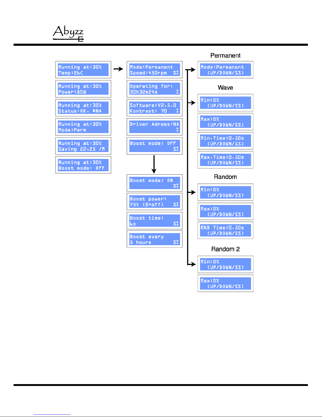
Fig. 3: Overview of messages
16
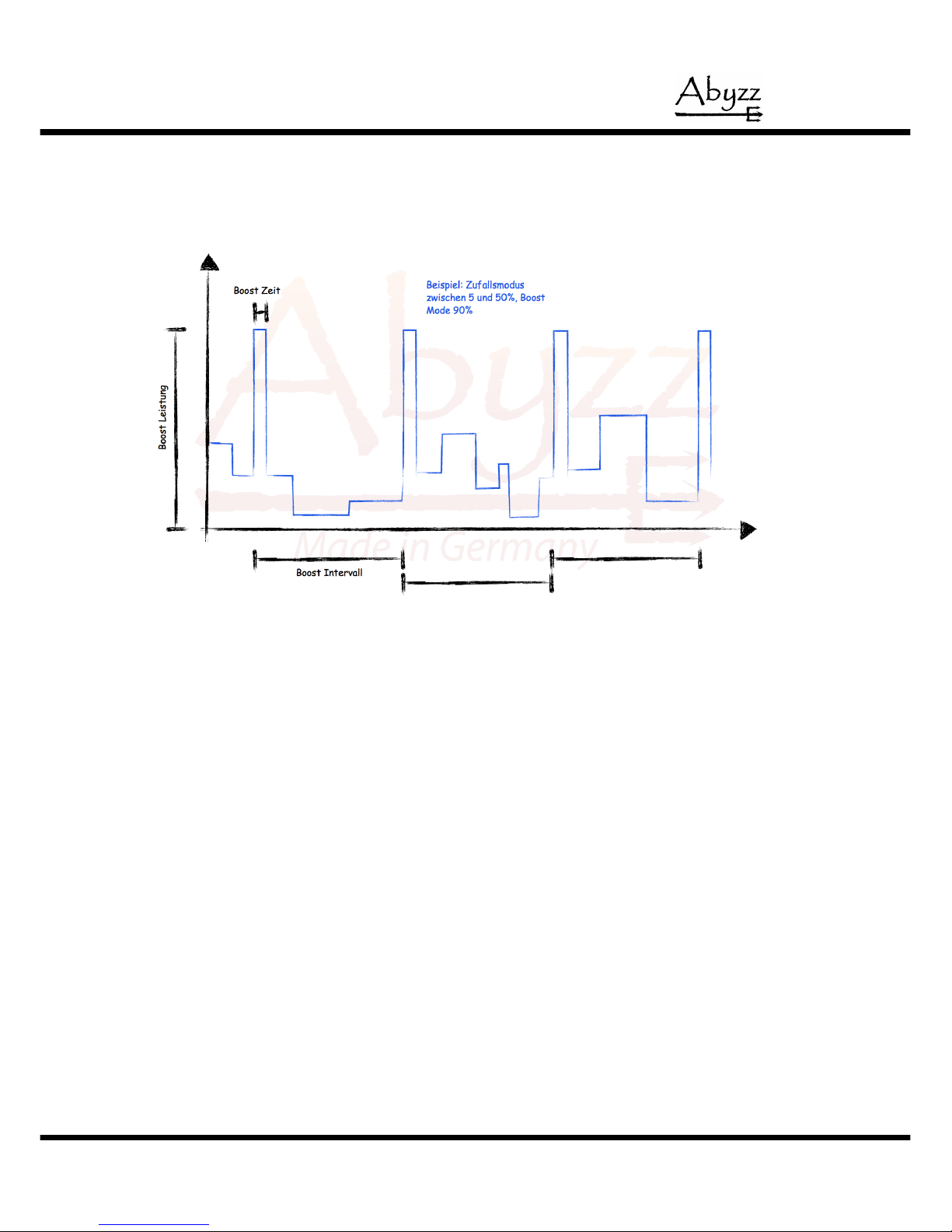
A special new feature is the Abyzz BOOSTMODE®, which makes it possible to set
up a short burst to get rid of debris. This burst can be programmed independently
to the operating mode chosen.
Fig. 4: Abyzz BOOSTMODE
In Fig. 4 you see as an example the burst, which is overriding the control of the
Abyzz random program.
17
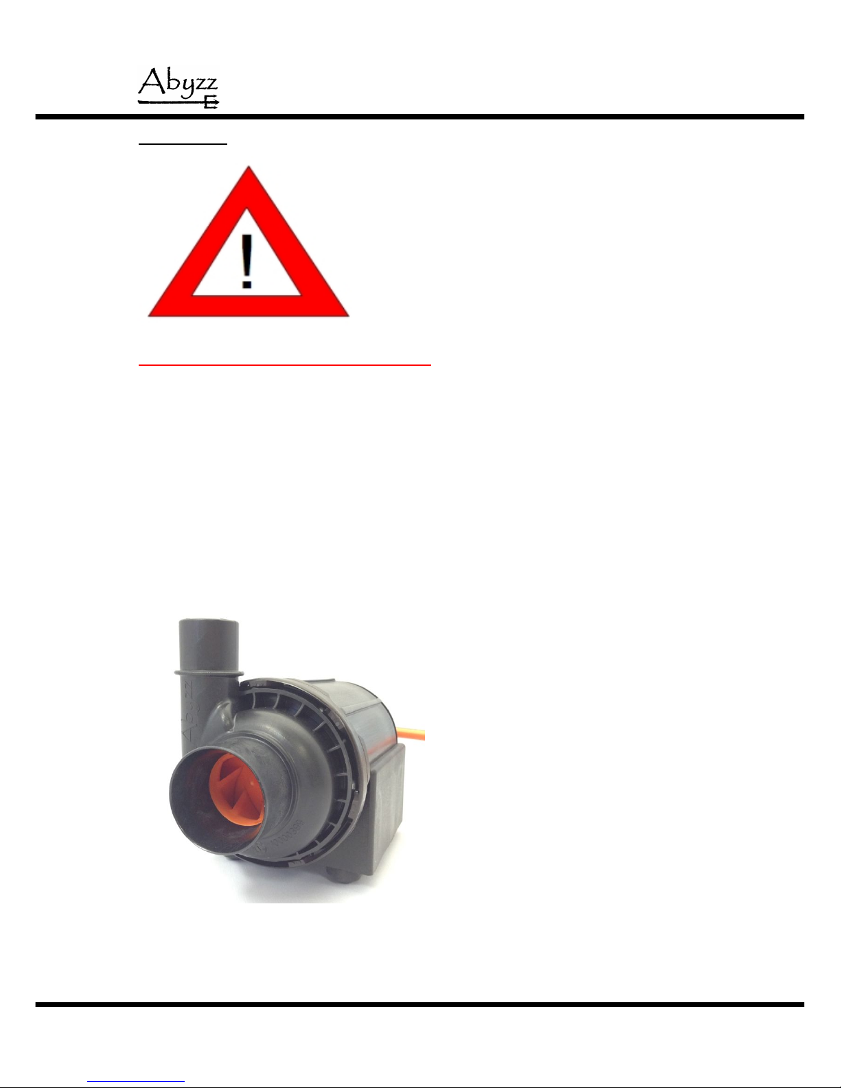
Maintenance
Caution - extremely strong magnetic field!
- Risk of death to people with pacemakers!
- Keep the impeller away from pacemakers, credit cards, data carriers, or
similar objects that are sensitive to magnetic fields.
- Risk of injury due to body parts becoming trapped.
- Do not place any metallic parts near to the impeller.
Abyzz pumps are practically maintenance-free if used properly. If the flow rate
drops, there may be particles of dirt that need to be removed in the impeller wheel.
Also, slight vibrations can be an indication that the impeller wheel is dirty.
To clean it, separate the pump head from the motor (bayonet coupling, see Fig. 6)
and pull out the impeller group.
Fig. 5: Pump with pump head
18
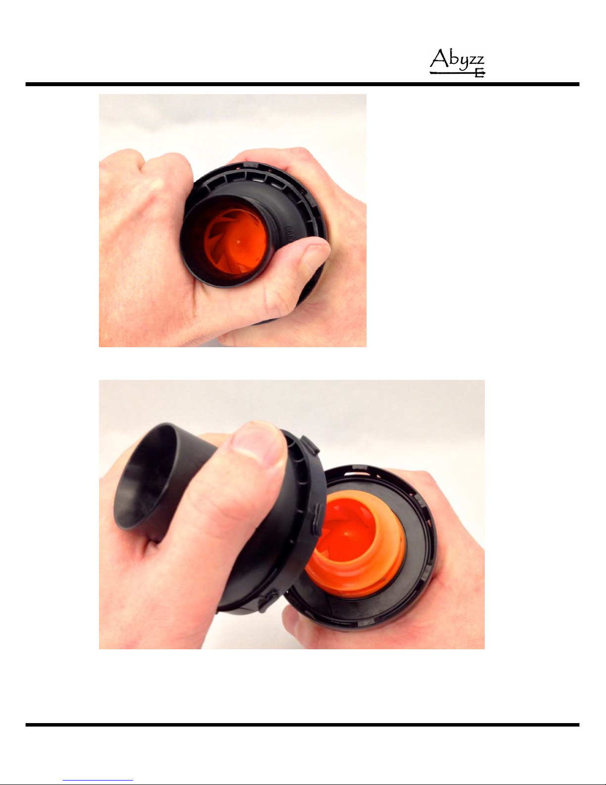
Fig. 6a/b: Disassembly of pump head
19

Fig. 7: Removing impeller group
O-rings and rubber parts suffer from unavoidable aging and should be replaced as
required. These parts are listed in the spare parts list and can be ordered from
Abyzz.
Make sure that the rear bearing is in the correct position inside the motor. If
necessary, push the bearing into position with a blunt object (e.g. the handle of a
screwdriver). Make sure that the O-ring for the vibration isolation and sealing is in
the right position before reassembling the pump.
Carefully place the impeller into the motor block and press the assembly into the
bearing seat until the bearing bracket is flush with the flange.
20
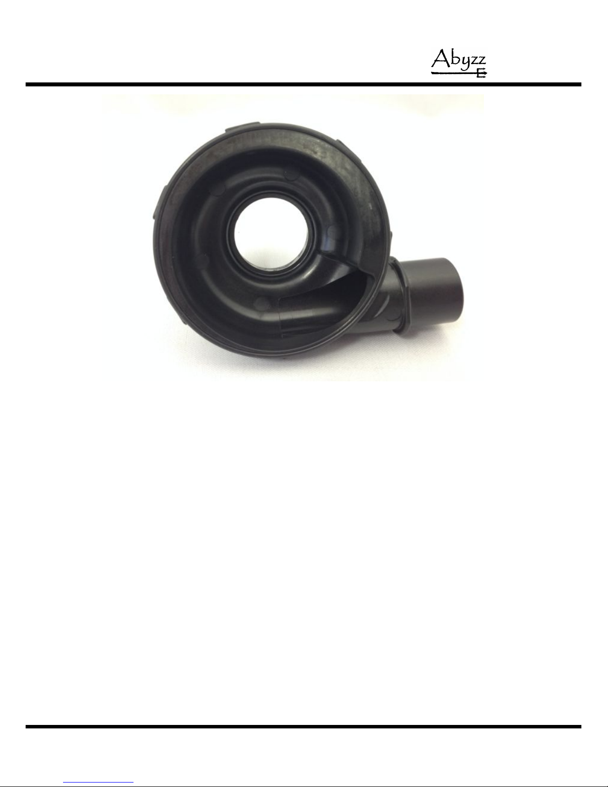
Fig. 8: O-ring position and assembly
Place the O-ring on the notch of the pump head and make sure it is properly
placed before closing the bayonet flange again.
21
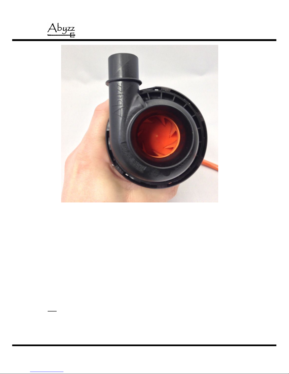
Fig. 9: Assembly of pump head
In systems that are constantly and intensively subjected to limescale (e.g. hard
coral ponds), the pump must be regularly descaled.
Tip:
We recommend that you use a weak vinegar solution to clean the pump to avoid
damaging it.
22

Guarantee
In accordance with the implied warranty, we provide a 12-month
guarantee. You can also extend the product guarantee period from 12
months to 10 years free of charge within 4 weeks of purchasing the
product (date of invoice) after registering your product successfully.
If you have a complaint, please contact us immediately and if needed,
send the device back - in its original packaging wherever possible and
with proof of purchase - directly to venotec. Please note that we cannot
accept non-prepaid deliveries. Such deliveries will be sent back without
being processed.
The guarantee covers material, functional, and production faults that can
occur when using the product as intended. It does not cover damage of
wearout or abrasive wear, transport damage, claims for compensation
above and beyond compensation for the product itself, or damage
resulting from improper use, negligence, incorrect installation, or
interventions and changes carried out by unauthorized persons. We
expressly exclude such scenarios from our scope of liability. Any
secondary damages such as the loss of coral, fish, or water damage
caused by pump failure or a lack of intake protection are expressly
excluded from guarantee and warranty claims. Calcination inside the
pump and any resulting damage to the product or motor, damage by use
as not intended and any damage to cables (e.g. chafed cables) are
expressly excluded from the warranty. The warranty is invalidated in the
following cases: Removed original plugs, use of non-original spare parts,
impeller wheel damage resulting from parts sucked into the pump, motor
damage caused by the tapering of the intake port or if the pump is
operated with a closed or partially closed ball valve in the intake area,
motor damage caused by persistent dry running, limescale damage
resulting from the improper use of chemicals or the use of unsuitable
chemicals, motor damage resulting from upstream external electronic
components or damage resulting from damp in the driver.
23

Techn i c a l changes
Due to the constant further development of our products and to innovations that, in
particular, serve to improve quality, safety, and technical progress, the
manufacturer reserves the right to make technical changes.
Troubleshooting
If, despite the high standard of quality, faults should occur, please use the
checklist below to rectify or restrict the problem. A number of faults are already
detected and displayed by the electronics.
Malfunction
Cause
Remedy
The display does not light
up and the LED flashes
a) Screensaver on
a) Press a button
The display does not light
up and the LED does not
flash
a) No mains voltage
a) Check the mains
connection
If the fault cannot be rectified,
there is a driver fault. In this
case, please contact the
service team.
Status: COMM FU!
a) Control unit communications
failed
a) Switch off the device and
switch back on after 10
seconds
Status: Imax!
a) Overcurrent fault, motor
overloaded
a) Check motor to make sure
that it can move freely
Status: MOTOR?
a) Motor not detected
a) Check connection to motor,
check plug
Status: TEMP!
a) Driver overheated
a) Let the driver cool down,
lower the ambient
temperature
Status: DRYRUN!
a) Motor has run dry or is drawing
in air
a) Check the water level,
check the pipes for leaks
Status: LOW VOLT!
a) Mains voltage too low
b) Too many devices on one lead
c) Mains lead too long
a) Check the mains voltage
b) Reduce the number of
devices
c) Reduce the length of the
lead, remove multi-socket
strips
Device is working but cannot
reach maximum power
If you cannot rectify the fault by checking the lines (incorrect connections), mains
voltage, and pump (smooth running, blockages), please contact your specialist
dealer. In such cases, please be ready to state the serial number of the driver and
of the motor. The serial numbers are on the blue serial number sticker or on the
packaging.
24

Disposal
As per Directive 2002/96/EC, this product cannot be disposed of in normal
household rubbish.
Within Germany, our customers can send old devices back to us free of charge for
proper recycling or disposal. The WEEE number for reporting to the EAR
(Germany registry of old electrical equipment) is:
DE 16546900
If you do not want to dispose of the product through us, you must bear the costs of
disposing of the product in accordance with legal requirements. In doing so, you
release us from our obligations as per Section 10 Paragraph 2 of the ElektroG
(Electrical and Electronic Equipment Act) and absolve us from all upcoming claims
from third parties.
Technical data:
Maximum flow rate : 8.500 l/h
Rated flow rate : 7.200 l/h
Discharge flow speed
maximum : 4,2 m/s
rated : 3,8 m/s
Delivery height maximum : 6,0 m
rated : 5,5 m
Rated input : 4...100 W
Operating voltage : 90...230V~, 50…60Hz
For details, see the characteristic curves in the appendix (fig. 10 et seq.). The
following calibrated devices were used for the measurement process:
Power test : Zimmer LMG 310
Quantity measurement : Krohne Optiflux 2100C
Discharge flow speed : Dorstmann P670
Pressure test : Kobold 220X1K9 Cl. 0,25
25

Materials
The following components/substances come into contact with the medium being
conveyed:
Housing
Pump head
Impeller wheel : ABS GF 20, PA-6
Flushing line : PVC, PU
Shaft : WCNi
Impeller : Titanium grade 2
Screws : Titanium grade 2
Bearings : SSIC
O-ring
Bearing seat
Device feet : NBR, CR, EPDM
Motor cable : PU
Jointing compound : PU
26

Fig. 10: Flow charts
27

Dimensions and weight
Fig. 11: Dimensions pump A100
28

CE declaration of conformity
GmbH
Am Nordkreuz 36
26180 Rastede
We hereby declare that the design of the pump system
Abyzz A200, A400, A200AS, IPX200, IPX400
complies with the following specifications:
EG-Richtlinie EMV 2004/108/EG
Applied harmonized standards:
DIN EN 61000-6-1
DIN EN 61000-6-2
DIN EN 61000-6-4
DIN EN 61000-3-2
This is a EMI class A product. In some environments it can
cause electromagnetic interference. In this case, it obligates to
the user to perform adequate measures.
29

Test report
Date : ____.____.________
Inspector : ______
Optical inspection : ______
Serial number driver : ____________________
Serial number motor : ____________________
Flow rate on test bench : __________ l/h
(nominal)
Maximum head pressure : __________ bar
Max power consumption : __________ W
Rotation OK : ______
Noise level OK : ______
_________________________
(signature inspector, stamp)
30

Notes
31

www.abyzz.de
www.venotec.de
32
 Loading...