

Page 1
Page 2

REVISIONS
INDEX P/N REVISION REVISION SECTION DATE
A Creation all 30/03/98
B RAH 581 AA Miscellaneous corrections 1, 3, 4 07/10/98
CONTENTS
1. HYDRAULIC & PNEUMATIC PRINCIPLES
2. ELECTRIC & ELECTRONIC PRINCIPLES
3. MAINTENANCE PROCEDURES
4. OUTPUT FORMAT
5. TRAINING SLIDES
Page 3

1. HYDRAULIC & PNEUMATIC PRINCIPLES
CONTENTS
1. GENERALITIES ..................................................................................................................................... 2
2. MICROS 60 OT HYDRAULIC................................................................................................................. 4
2.1. With bottles..................................................................................................................................... 4
2.1.1. Transmission tubes list ........................................................................................................... 4
2.1.2. Hydropneumatic connections ................................................................................................. 5
2.2. Pack ............................................................................................................................................... 6
2.2.1. Transmission tubes list ........................................................................................................... 6
2.2.2. Hydropneumatic connections ................................................................................................. 7
2.3. Hydraulic cycle description ............................................................................................................. 8
2.3.1. Atmosphere circuit.................................................................................................................. 8
2.3.2. Diluent circuit .......................................................................................................................... 8
2.3.3. Clean circuit............................................................................................................................ 8
2.3.4. Lyse circuit.............................................................................................................................. 8
2.3.5. WBC/RBC counting circuit...................................................................................................... 8
2.3.6. Drain/bubbling circuit .............................................................................................................. 8
3. MICROS 60 CT HYDRAULIC............................................................................................................... 15
3.1. With bottles................................................................................................................................... 15
3.1.1. Transmission tubes list ......................................................................................................... 15
3.1.2. Hydropneumatic connections ...............................................................................................16
3.2. Pack ............................................................................................................................................. 17
3.2.1. Transmission tubes list ......................................................................................................... 17
3.2.2. Hydropneumatic connections ...............................................................................................18
3.3. Hydraulic cycle description ........................................................................................................... 19
3.3.1. Atmosphere circuit................................................................................................................ 19
3.3.2. Diluent circuit ........................................................................................................................ 19
3.3.3. Clean circuit.......................................................................................................................... 19
3.3.4. Lyse circuit............................................................................................................................ 19
3.3.5. WBC/RBC counting circuit.................................................................................................... 19
3.3.6. Drain/bubbling circuit ............................................................................................................ 19
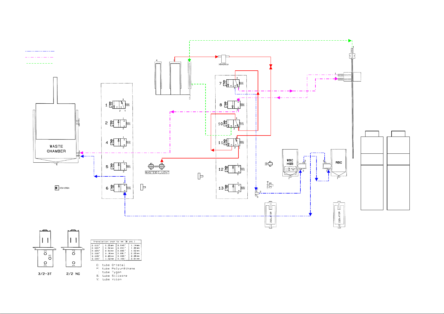
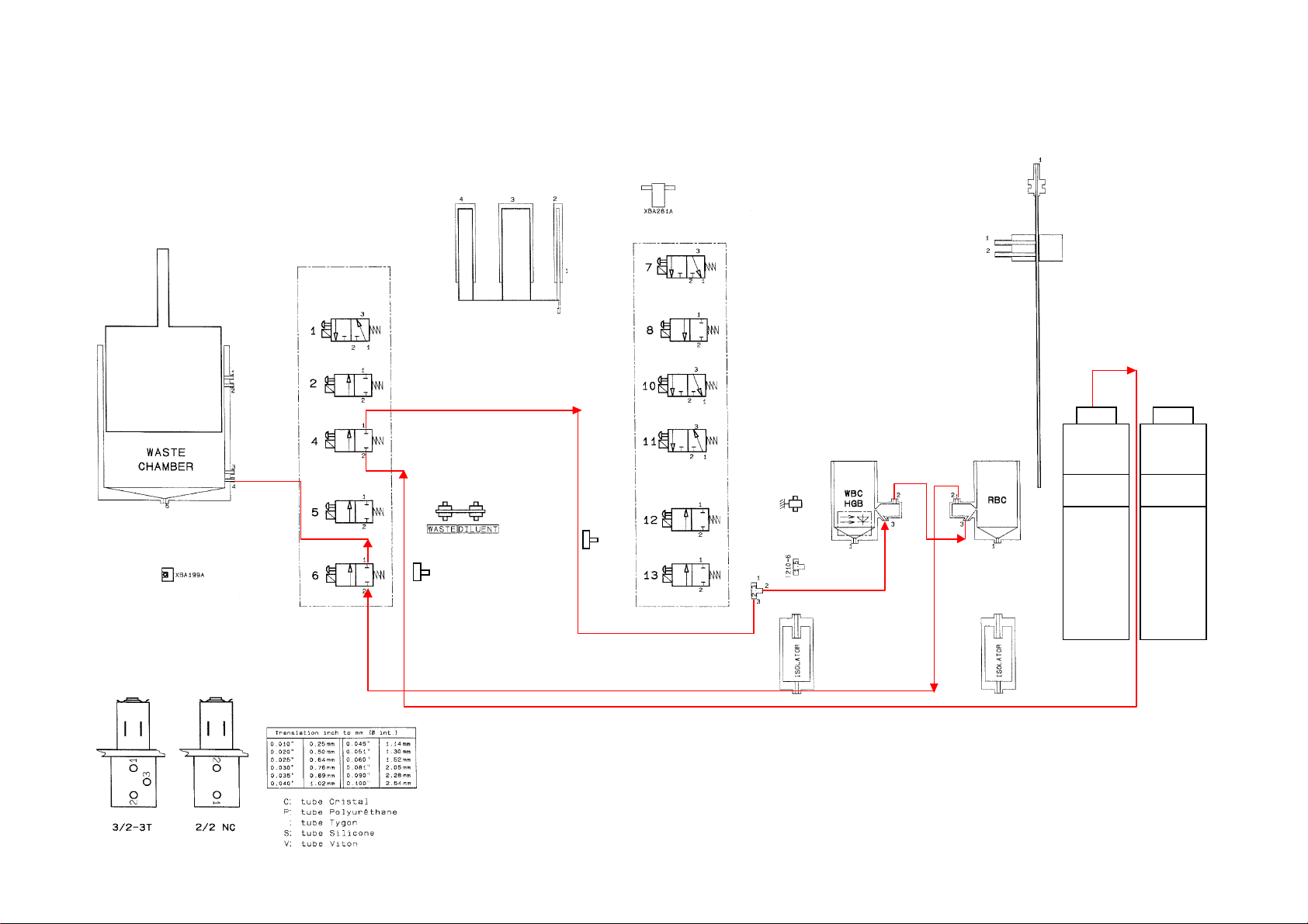
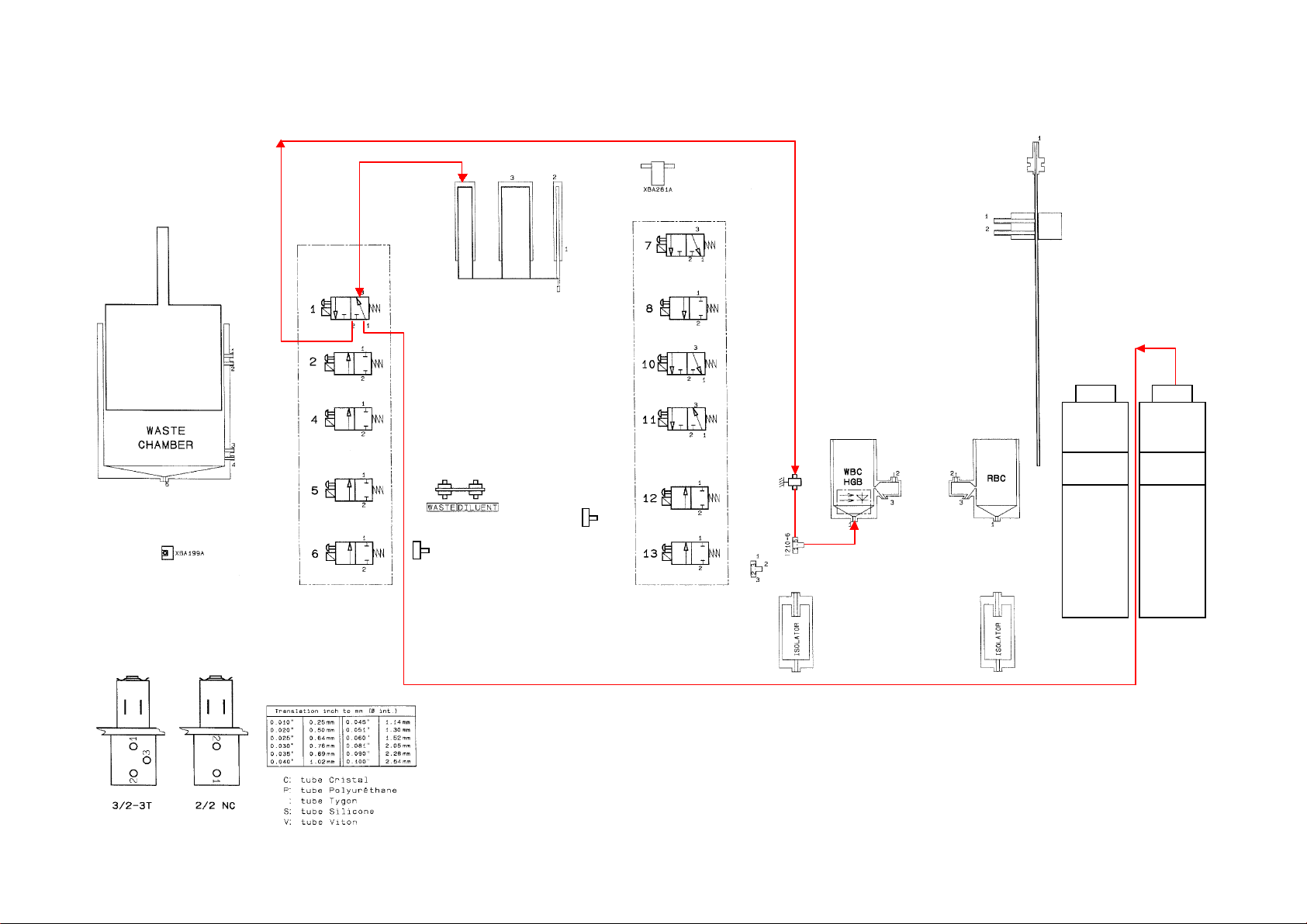
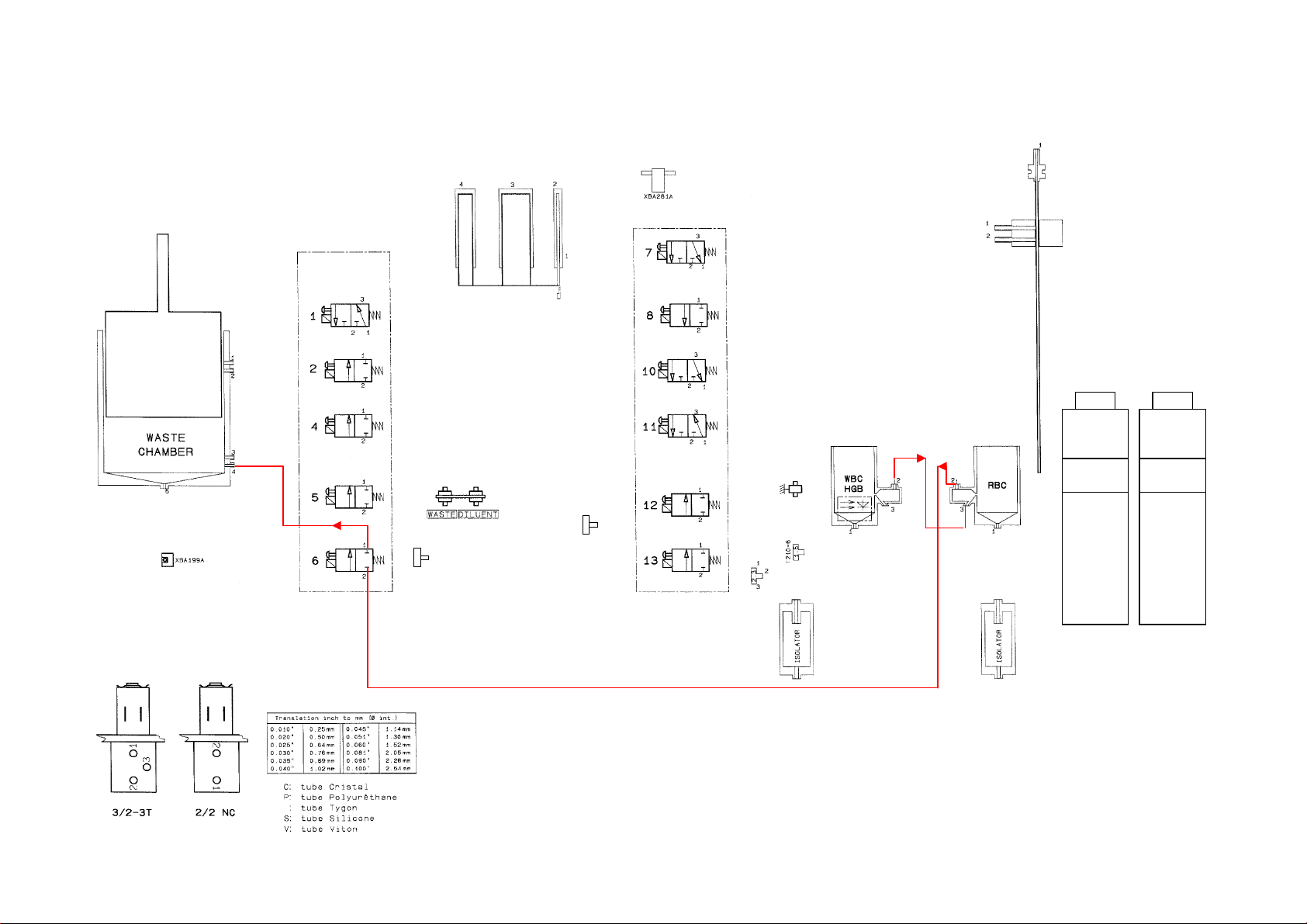
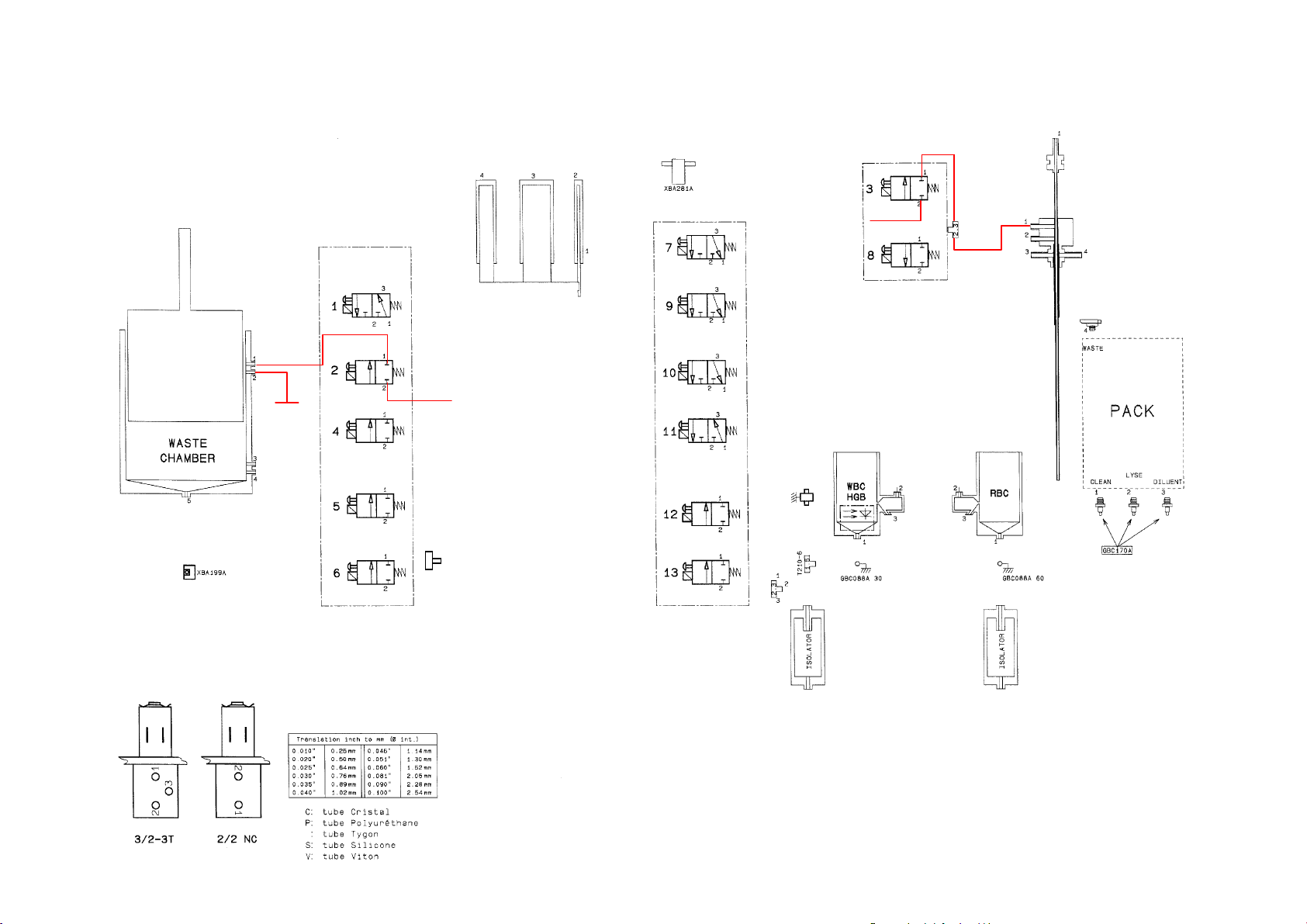
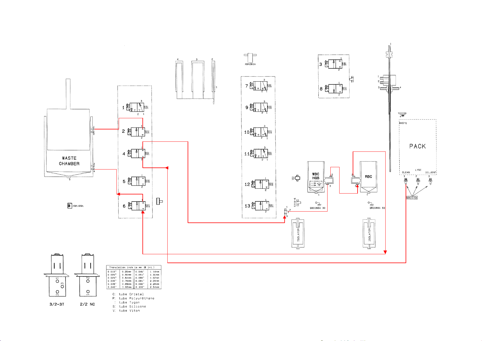
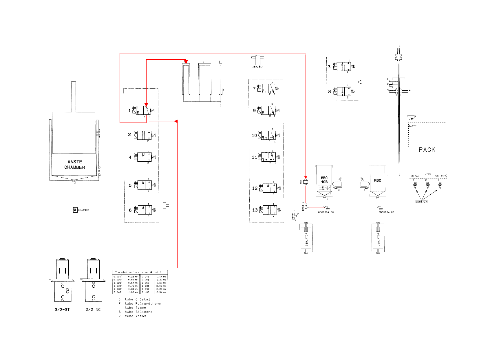
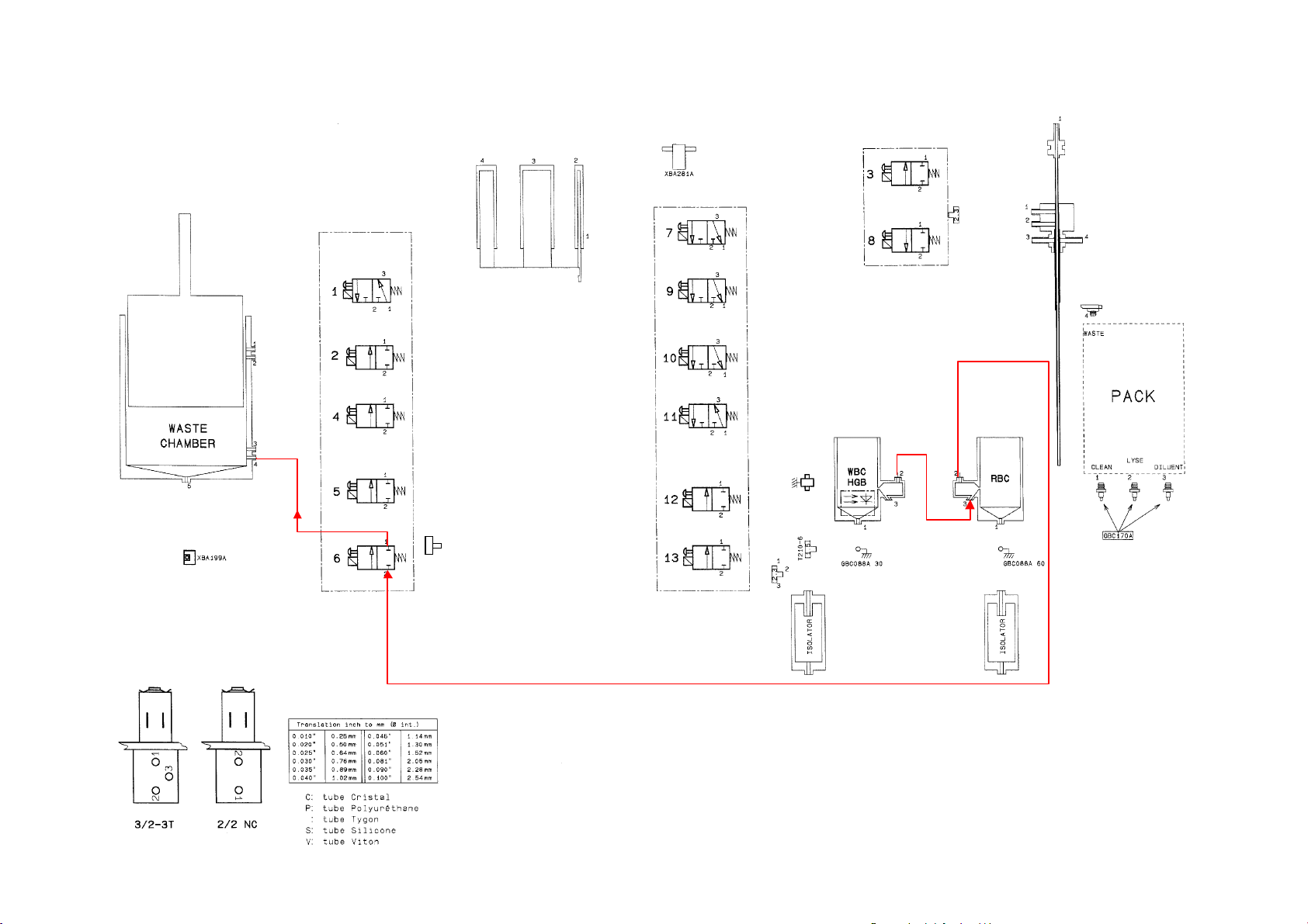
4. PNEUMA TIC DIAGRAMS..................................................................................................................... 26
4.1. Micros 60 CT bottle version .......................................................................................................... 26
4.2. Micros 60 CT pack version ........................................................................................................... 26
4.3. Micros 60 OT bottle version.......................................................................................................... 26
4.4. Micros 60 OT pack version........................................................................................................... 26
RAA 009 A Ind.A
Page 1/1 18/06/98
Page 4
1. HYDRAULIC & PNEUMATIC PRINCIPLES
1. GENERALITIES
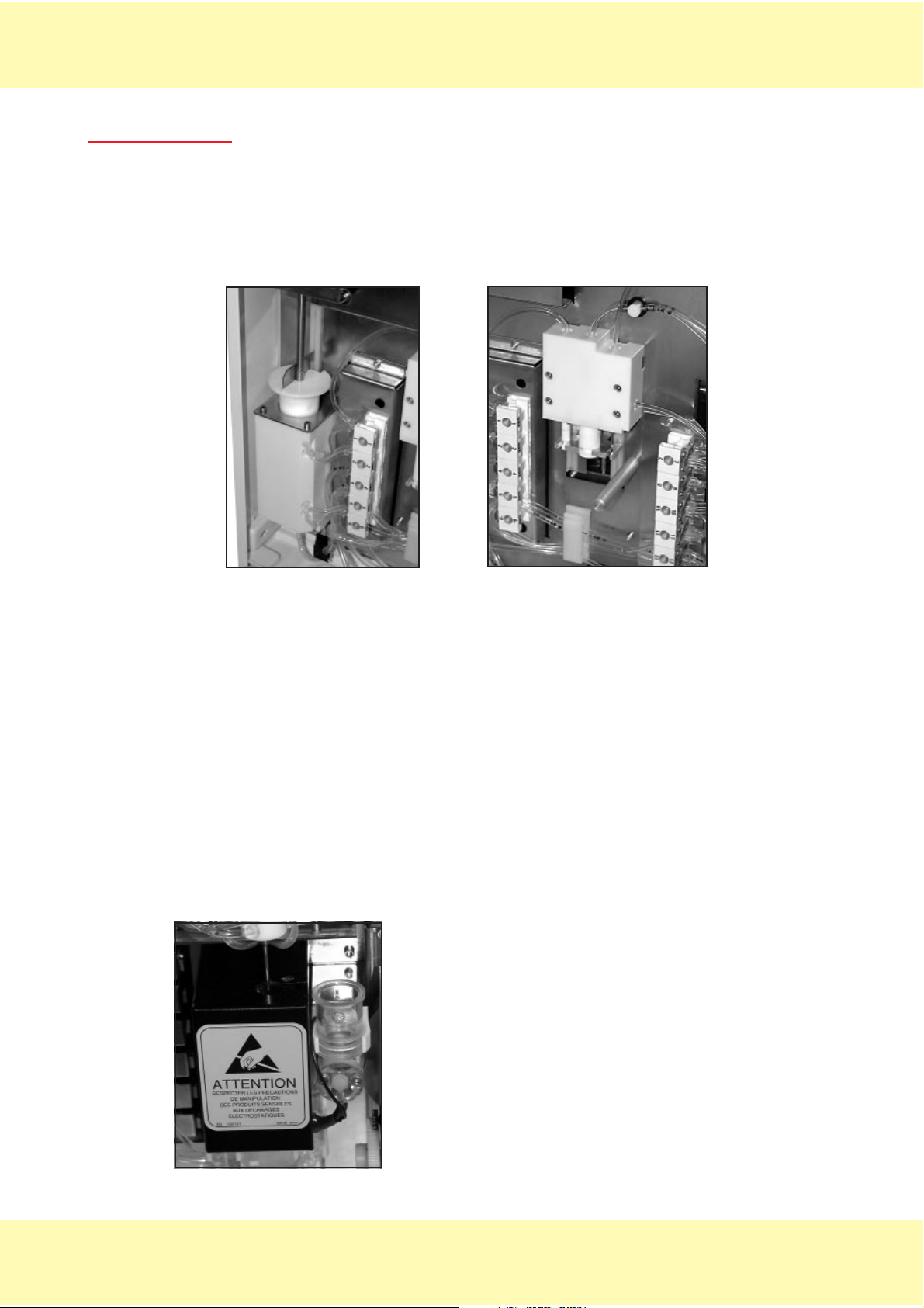
MICROS 60 instrument has been designed for simple mechanical operations.
4 stepper motors provide movements to mechanical assemblies.
Pressure and vacuum are provided by the vacuum/waste syringe up and down movements
(diag 1).
Liquid movements are achieved either by means of mechanical assembly movements (liquid
Diag.1
syringes diag 2) or pressure/vacuum and simultaneous action of specific valves.
• Dilution chambers (Diag .3)
WBC/HGB and RBC chambers are made of GRILAMID TR55 LY injected.
The diode and the cell of the spectrophotometer are glued on the WBC/HGB chamber.
Chamber positions can be modified in order to obtain the best sampling position possible.
Dilutions :
First dilution is carried out in the WBC/HGB chamber (with a bubbling phasis).
The RBC blood sample is aspirated from this dilution.
Lyse is sent from the drain nipple of the WBC/HGB chamber.
Counts have a duration of 2 x 6 seconds.
(see procedures RAS 188 A and RAS 187 A for cycle hydraulic details)
Rinse :
To obtain the best rinse in the counting heads, diluent is sent
from the liquid syringes. This is carried out before, between
and after the two counts.
Diag.2
RAA 009 A Ind.A
Page 1/2
18/06/98
Page 5

1. HYDRAULIC & PNEUMATIC PRINCIPLES
IMPORTANT
A window on the HGB/WBC chamber allows the needle to move down into the chamber
and to inject reagents. As important light or variation of light can cause HGB result
drifts, close instrument cover and door before running blood analyses.
Bubbling
Insulators avoid polluted liquid overflows during bubbling phasis. they also allows an accurate
adjustment of the bubbling volume.
MICROS 60 CT specifics :
- The piercing needle is equipped with two injectors to obtain a homogeneous diluent flow
during needle rinsing phasis (see procedures RAS 188 A and RAS 187 A).
- Atmosphere is provided to sample tubes to allow a correct aspiration of blood.
:
RAA 009 A Ind.A
Page 1/3 18/06/98
Page 6

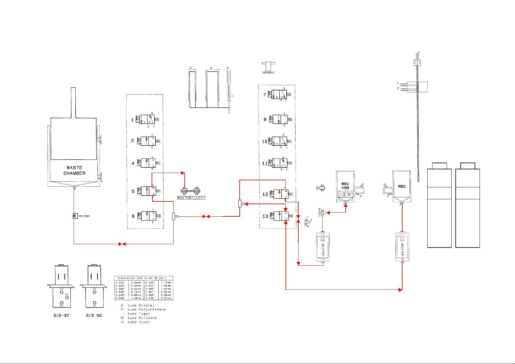
1. HYDRAULIC & PNEUMATIC PRINCIPLES
2. MICROS 60 OT HYDRAULIC
Liquid circuits, hydropneumatic connections, as well as the transmission tubes used, are
described in the following chart tables.
2.1. With bottles
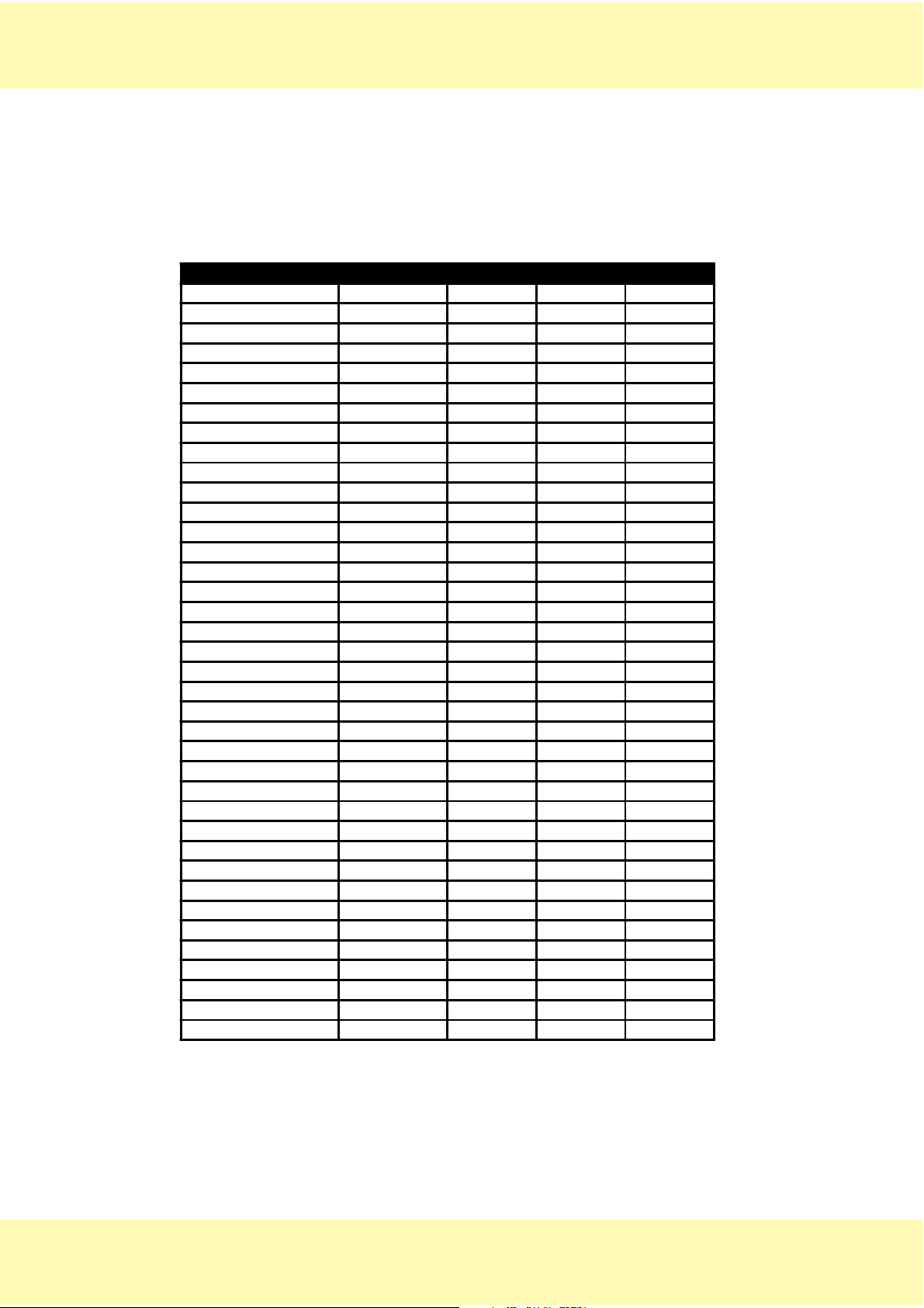
2.1.1. Transmission tubes list
DESIGNATION PART NUMBER DIAMETER LEN GTH QUANTITY
SLEEVE HPS3 DBD005A 5-9 0.5
T CONNECTOR EAB006B 2.3 3
T CONNECTOR EAB032A 1.5 1
TUBE CAP EAC017A 2.5 1
TYGON TUBE 0.051" EAE006A 1.30 140 1
TYGON TUBE 0.051" EAE006A 1.30 350 1
TYGON TUBE 0.060" EAE007A 1.52 20 1
TYGON TUBE 0.060" EAE007A 1.52 40 3
TYGON TUBE 0.060" EAE007A 1.52 50 1
TYGON TUBE 0.060" EAE007A 1.52 60 1
TYGON TUBE 0.060" EAE007A 1.52 70 2
TYGON TUBE 0.060" EAE007A 1.52 80 1
TYGON TUBE 0.060" EAE007A 1.52 150 1
TYGON TUBE 0.060" EAE007A 1.52 170 1
TYGON TUBE 0.060" EAE007A 1.52 220 1
TYGON TUBE 0.060" EAE007A 1.52 240 1
TYGON TUBE 0.060" EAE007A 1.52 300 1
TYGON TUBE 0.060" EAE007A 1.52 370 1
TYGON TUBE 0.060" EAE007A 1.52 410 1
TYGON TUBE 0.060" EAE007A 1.52 450 2
TYGON TUBE 0.060" EAE007A 1.52 480 1
TYGON TUBE 0.081" EAE008A 2.05 20 1
TYGON TUBE 0.081" EAE008A 2.05 35 1
TYGON TUBE 0.081" EAE008A 2.05 200 1
TYGON TUBE 0.081" EAE008A 2.05 330 1
TYGON TUBE 0.081" EAE008A 2.05 1080 1
TYGON TUBE 0.090" EAE009A 2.28 20 2
TYGON TUBE 0.090" EAE009A 2.28 50 1
TYGON TUBE 0.090" EAE009A 2.28 60 2
TYGON TUBE 0.090" EAE009A 2.28 120 1
TYGON TUBE 0.090" EAE009A 2.28 140 1
TYGON TUBE 0.090" EAE009A 2.28 150 1
TYGON TUBE 0.090" EAE009A 2.28 190 1
BLUE TYGON TUBE 0.090" EAE036A 2.28 1100 1
SLEEVE GAL098A 30
TUBE SHIELD GBC088A 4.4 30 1
TUBE SHIELD GBC088A 4.4 60 1
RAA 009 A Ind.A
Page 1/4
18/06/98
Page 7

1. HYDRAULIC & PNEUMATIC PRINCIPLES
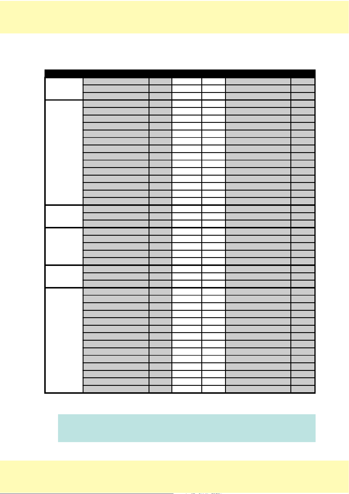
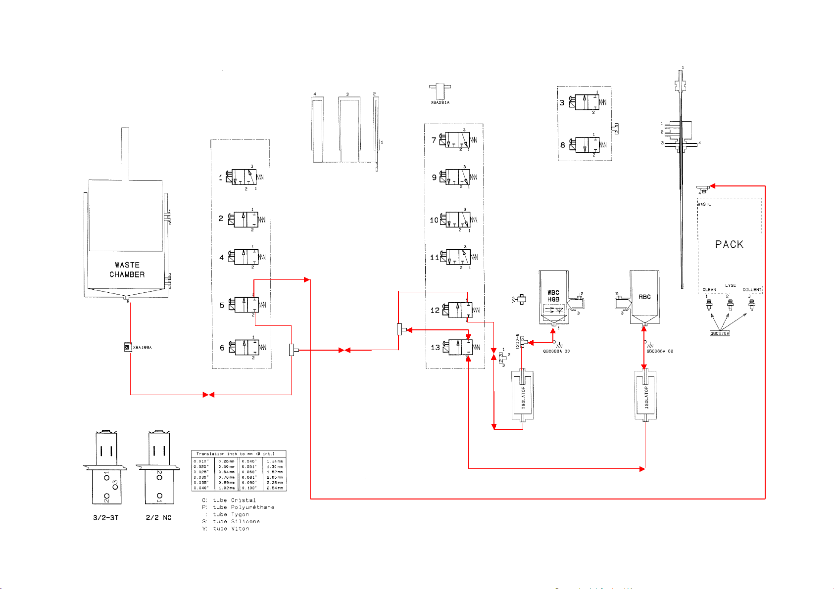
2.1.2. Hydropneumatic connections
CIRCUIT FROM SLEEVE DIAM LENGTH TO SLEEVE
AIR
DILUENT
CLEAN
LYSE
WBC/RBC
COUNTING
DRAIN/BUBBLING
(atmosphere) 2.28 190 Liquid valve 2_2
Liquid valve 2_1 Y2.28 50Waste-chamb._1 Y
Waste-chamb._2 2.28 20 Cap EAC017A
Diluent inpu t 2.05 330 Liquid valve11_1
Liquid valve11_3 Y1.52 220Temp. sensor xba281a Y
Temp. sensor. xba281a Y1.52 40Liquid syringes_3 Y
Liquid valve11_2 Y1.52 40Liquid valve10_3 Y
Liquid valve10_1 Y1.52 70Liquid valve7_3 Y
Liquid valve7_1 Y1.52 370needle rinsing block._2
Needle rinsing block._1 1.52 410 Liquid valve8_1
Liquid valve8_2 Y1.52 300Waste-chamb._3
Liquid valve 7_2 Y1.52 240Té 2.3_1
Té 2.3_2 1.52 50 Bac W BC/HGB_3
Liquid valve10_2 Y1.30 140Liquid syringes_1 Y
Liquid syringes_2 Y1.30 350needle_1
Liquid syringes_2 Y Needle_1 Y
Clean bottle 2.28 1100 blue Liquid valve4_2 Y
Liquid valve4_1 Y1.52 450T connector 2.3_3
Lyse bottle 2.05 1080 liquid valve 1_1
Liquid valve1_3 1.52 150 Liquid syringes _4
Liquid valve1_2 1.52 480 WBC grounding connector
WBC grounding connector 1.52 20 T connector 1.5_1
WBC/HGB_2 chamber 1.52 170 RBC_3 chamber
RBC_2 chamber 1.52 450 liquid valve 6_2 Y
Liquid valve 6_1 Y1.52 60Waste-chamb._4
WBC/HGB_1 chamber 1.52 40 T connector 1.5_2
WBC/HGB_1 chamber gbc088a 30 T connector 1.5_2
T connector 1.5_3 1.52 80 Ins ulator WBC _1
Insulator WB C_2 2.28 120 liquid valve12_2 Y
Liquid valve12_1 Y2.05 35T connector 2.3_1
RBC_1 chamber 1.52 70 In sulator RBC_ 1
RBC_1 chamber gbc088a 60 In sulator RB C_1
Insulator RBC_ 2 2.28 150 liquid valve13_2 Y
Liquid valve13_1 Y2.05 20T connector 2.3_2
T connector 2.3_3 2.05 200 T connector 2.3_2
T connector 2.3_3 2.28 20 Cell xba199a Y
Cell xba199a Y2.28 60Waste-chamb._5 Y
T connector 2.3_1 2.28 60 Liquid valve5_2 Y
Liquid valve5_1 2.28 140 Waste ouput
NOTE
RAA 009 A Ind.A
Read this table as follows in this example :
The Liquid valve 7_2 corresponds to the ouput 2 of the valve number 7 (see
attached pneumatic diagram).
Page 1/5 18/06/98
Page 8
1. HYDRAULIC & PNEUMATIC PRINCIPLES
2.2. Pack
2.2.1. Transmission tubes list
DESIGNATION PART NUMBER DIAMETER LENGTH QUANTITY
SLEEVE HPS3 DBD005A 5-9 0.5
T CONNECTOR EAB006B 2.3 3
T CONNECTOR EAB032A 1.5 1
TUBE CAP EAC017A 2.5 1
TYGON TUBE 0.051" EAE006A 1.30 140 1
TYGON TUBE 0.051" EAE006A 1.30 350 1
TYGON TUBE 0.060" EAE007A 1.52 20 1
TYGON TUBE 0.060" EAE007A 1.52 40 3
TYGON TUBE 0.060" EAE007A 1.52 50 1
TYGON TUBE 0.060" EAE007A 1.52 60 1
TYGON TUBE 0.060" EAE007A 1.52 70 2
TYGON TUBE 0.060" EAE007A 1.52 80 1
TYGON TUBE 0.060" EAE007A 1.52 150 1
TYGON TUBE 0.060" EAE007A 1.52 170 1
TYGON TUBE 0.060" EAE007A 1.52 220 1
TYGON TUBE 0.060" EAE007A 1.52 240 1
TYGON TUBE 0.060" EAE007A 1.52 300 1
TYGON TUBE 0.060" EAE007A 1.52 370 1
TYGON TUBE 0.060" EAE007A 1.52 410 1
TYGON TUBE 0.060" EAE007A 1.52 450 2
TYGON TUBE 0.060" EAE007A 1.52 480 1
TYGON TUBE 0.081" EAE008A 2.05 20 1
TYGON TUBE 0.081" EAE008A 2.05 35 1
TYGON TUBE 0.081" EAE008A 2.05 200 1
TYGON TUBE 0.081" EAE008A 2.05 590 1
TYGON TUBE 0.090" EAE009A 2.28 20 2
TYGON TUBE 0.090" EAE009A 2.28 50 1
TYGON TUBE 0.090" EAE009A 2.28 60 2
TYGON TUBE 0.090" EAE009A 2.28 120 1
TYGON TUBE 0.090" EAE009A 2.28 150 1
TYGON TUBE 0.090" EAE009A 2.28 190 1
TYGON TUBE 0.090" EAE009A 2.28 510 1
TYGON TUBE 0.090" EAE009A 2.28 550 1
TYGON TUBE 0.090" EAE009A 2.28 1100 1
SLEEVE GAL098A 31
TUBE SHIELD GBC088A 4.4 30 1
TUBE SHIELD GBC088A 4.4 60 1
METALLIC SHEATH GBC170A 5.2 35 3
RAA 009 A Ind.A
Page 1/6
18/06/98
Page 9
1. HYDRAULIC & PNEUMATIC PRINCIPLES
2.2.2. Hydropneumatic connections
CIRCUIT FROM SLEEVE DIAMETER LE NG TH TO SLEEVE
(atmosphere) 2.28 190 Liquid valve 2_2
AIR
DILUENT
CLEAN
LYSE
WBC/RBC
counting
DRAIN /
BUBBLING
Liquid valve 2_1 Y 2.2 8 50 Waste-chamb._1 Y
Waste-chamb._2 2.28 20 cap EAC017A
Pack_3 (Dil uent) 2.28 550 Liquid valve 11_1 Y
Pack_3 (Dil uent) gbc170a
Liquid valve 11_3 Y 1.52 220 temp. sensor xba281a Y
temp. sensor xba281a Y 1.52 40 Liquid syringes _3 Y
Liquid valve 11_2 Y 1.52 40 Liquid valve 10_3 Y
Liquid valve 10_1 Y 1.52 70 Liquid valve 7_3 Y
Liquid valve 7_1 Y 1.5 2 370 Needle rinsing block_2
needle rinsing block._1 1.52 410 Liquid valve 8_1
Liquid valve 8_2 Y 1.5 2 300 Waste-chamb._3
Liquid valve 7_2 Y 1.5 2 240 T connecto r 2.3_1
T connector 2. 3_2 1.52 50 Bac WBC/HGB_3
Liquid valve 10_2 Y 1.30 140 Liquid syringes _1 Y
Liquid syringes _2 Y 1.30 350 NEEDLE_ 1
Liquid syringes _2 Y NEEDLE_1 Y
Pack-1 (Clean ) 2.28 510 Liquid valve 4_2 Y
Pack-1 (Clean ) gbc170a
Liquid valve 4_1 Y 1.5 2 450 T connecto r 2.3_3
Pack_2 (Lyse) 2.05 590 Liquid valve 1_1
Pack_2 (Lyse) gbc170a
Liquid valve 1_3 1.52 150 Liquid syringes _4
Liquid valve 1_2 1.52 480 WBC grounding connector
WBC grounding connector 1.52 20 T connector 1.5_ 1
WBC/HGB ch amber _ 2 1.52 170 RBC chamb er _3
RBC chamber _2 1.52 450 Liquid valve 6_2 Y
Liquid valve 6_1 Y 1.5 2 60 Waste-chamb._4
WBC/HGB cham ber _1 1.52 40 T connector 1. 5_2
WBC/HGB cham ber _1 gbc088a 30 T connector 1. 5_2
T connector 1. 5_3 1.52 80 Insulator WBC_1
Insulator WBC_2 2.28 120 Liquid valve 12_2 Y
Liquid valve 12_1 Y 2.05 35 T connecto r 2.3_1
Bac RBC_1 1.52 70 Insulator RBC_1
Bac RBC_1 gbc 088a 60 Insulator RBC_1
Insulator RBC_2 2.28 150 Liquid valve 13_2 Y
Liquid valve 13_1 Y 2.05 20 T connecto r 2.3_2
T connector 2. 3_3 2.05 200 T connec tor 2.3_2
T connector 2. 3_3 2.28 20 Cellule xba 199a Y
Cell xba199a Y 2.28 60 Waste-chamb._5 Y
T connector 2. 3_1 2.28 60 Liquid valve 5_2 Y
Liquid valve 5_1 2.28 1100 Pack_4 (Waste)
NOTE
RAA 009 A Ind.A
Read this table as follows in this example :
The Liquid valve 7_2 corresponds to ouput 2 of the valve number 7 (see
attached pneumatic diagram).
Page 1/7 18/06/98
Page 10

1. HYDRAULIC & PNEUMATIC PRINCIPLES
2.3. Hydraulic cycle description
2.3.1. Atmosphere circuit
2.3.2. Diluent circuit
2.3.3. Clean circuit
2.3.4. Lyse circuit
2.3.5. WBC/RBC counting circuit
2.3.6. Drain/bubbling circuit
RAA 009 A Ind.A
Page 1/8
18/06/98
Page 11

RAA 009 A ind B
ATMOSPHERE CIRCUIT
EAC 017 A
CLEAN LYSE
Page 12
RAA 009 A ind B
COUNTING HEAD RINSE CIRCUIT
OUTER NEEDLE RINSE CIRCUIT
DILUENT CIRCUIT
INNER NEEDLE CIRCUIT
CLEAN LYSE
Page 13
RAA 009 A ind B
CLEAN CIRCUIT
CLEAN LYSE
Page 14
RAA 009 A ind B
LYSE CIRCUIT
CLEAN LYSE
Page 15
RAA 009 A ind B
WBC / RBC COUNTING PHASIS
CLEAN LYSE
Page 16
RAA 009 A ind B
DRAIN / BUBBLING CIRCUIT
CLEAN LYSE
Page 17
1. HYDRAULIC & PNEUMATIC PRINCIPLES
3. MICROS 60 CT HYDRAULIC
3.1. With bottles
3.1.1. Transmission tubes list
DESIGNATION PART NUMBER DIAMETER LEN GTH QUANTITY
T CONNECTOR EAB006B 2.3 4
STRAIGHT CONNECTOR EAB015A 1.5/2.5 3
T CONNECTOR EAB032A 1.5 2
TUBE CAP EAC017A 2.5 1
TYGON TUBE 0.040" EAE005A 1.02 110 1
TYGON TUBE 0.040" EAE005A 1.02 335 1
TYGON TUBE 0.060" EAE007A 1.52 15 3
TYGON TUBE 0.060" EAE007A 1.52 20 2
TYGON TUBE 0.060" EAE007A 1.52 40 4
TYGON TUBE 0.060" EAE007A 1.52 50 2
TYGON TUBE 0.060" EAE007A 1.52 60 1
TYGON TUBE 0.060" EAE007A 1.52 70 2
TYGON TUBE 0.060" EAE007A 1.52 80 1
TYGON TUBE 0.060" EAE007A 1.52 100 1
TYGON TUBE 0.060" EAE007A 1.52 150 1
TYGON TUBE 0.060" EAE007A 1.52 170 1
TYGON TUBE 0.060" EAE007A 1.52 220 1
TYGON TUBE 0.060" EAE007A 1.52 240 1
TYGON TUBE 0.060" EAE007A 1.52 420 2
TYGON TUBE 0.060" EAE007A 1.52 450 2
TYGON TUBE 0.060" EAE007A 1.52 480 1
TYGON TUBE 0.081" EAE008A 2.05 20 1
TYGON TUBE 0.081" EAE008A 2.05 35 1
TYGON TUBE 0.081" EAE008A 2.05 200 1
TYGON TUBE 0.081" EAE008A 2.05 330 1
TYGON TUBE 0.081" EAE008A 2.05 650 1
TYGON TUBE 0.081" EAE008A 2.05 1080 1
TYGON TUBE 0.090" EAE009A 2.28 20 2
TYGON TUBE 0.090" EAE009A 2.28 50 1
TYGON TUBE 0.090" EAE009A 2.28 60 3
TYGON TUBE 0.090" EAE009A 2.28 120 1
TYGON TUBE 0.090" EAE009A 2.28 140 1
TYGON TUBE 0.090" EAE009A 2.28 150 1
TYGON TUBE 0.090" EAE009A 2.28 190 1
SILICONE TUBE EAE025A 1.5/3.5 50 2
BLUE TYGON TUBE 0.090" EAE036A 2.28 1100 1
SLEEVE GAL098A 32
TUBE SHIELD GBC088A 4.4 30 1
TUBE SHIELD GBC088A 4.4 60 1
RAA 009 A Ind.A
Page 1/15 18/06/98
Page 18

1. HYDRAULIC & PNEUMATIC PRINCIPLES
3.1.2. Hydropneumatic connections
CIRCUIT FROM SLEEVE DIAMETER LENGTH TO SL EEVE
(atmosphere) 2.28 190 Liqu id valve 2_2
Liquid valve 2_1 Y2.2850Waste-chamb._1 Y
AIR
DILUENT
CLEAN
LYSE
WBC/RBC
counting
DRAIN /
BUBBLING
Waste-chamb._2 2.28 20 cap EAC017A
(atmosphere) 2.28 60 Liquid valve 3_ 2
Liquid valve 3_1 1.52 40 T connector 2.3_1
Diluent input 2.05 330 Liquid va lve 11_1
Liquid valve 11_3 Y1.52220temp sensor. xba281a Y
temp sensor. xba281a Y1.5240liquid syringes_3 Y
Liquid valve 11_2 Y1.5240Liquid valve 10_3 Y
Liquid valve 10_1 Y1.5270Liquid valve 7_3 Y
Liquid valve 7_1 Y1.5250Liquid valve 9_3 Y
Liquid valve 9_1 Y1.52420Needle rinsing block._2
Liquid valve 9_2 Y1.52420T connector 1.5_2
T connector 1.5_1 S 1.5/3.5 50 Needle rinsing block._3
T connector 1.5_3 S 1.5/3.5 50 Needle rinsing block._4
Liquid valve 7_2 Y1.52240T connector 2.3_1
T connector 2.3_2 1.52 50 WBC/HGB chamber_3
Liquid valve 10_2 Y1.5215Connector 1.5/2.5
Connector 1.5/2.5 1.02 110 Co nnector 1.5/2 .5
Connector 1.5/2.5 1.52 15 liquid syrin ges_1 Y
liquid syringe s_2 Y1.5215Connector 1 .5/2.5
Connector 1.5/2.5 1.02 335 needle_1
Connector 1.5/2.5 Y needle_1 Y
Needle rinsing block._1 1.52 100 T connector 2.3_3
T connector 2.3_2 1.52 20 Liqu id valve 8_1
Liquid valve 8_2 2.05 650 Waste-chamb._3
Clean bottle 2.28 1100 blue Liqu id valve 4_2 Y
Liquid valve 4_1 Y1.52450T connector 2.3_3
Lyse bottle 2.05 1080 Liquid valve 1_1
Liquid valve 1_3 1.52 150 liquid syringe s_4
Liquid valve 1_2 1.52 480 WBC grounding connector
WBC grounding connector 1.52 20 T connector 1.5_1
WBC/HGB chamber _2 1.52 170 RBC chamber_3
RBC chamber_2 1.52 450 Liquid valve 6_ 2 Y
Liquid valve 6_1 Y1.5260Waste-chamb._4
WBC/HGB Chamber_1 1.52 40 T connector 1.5_2
WBC/HGB Chamber_1 gbc088a 30 T connector 1.5_2
T connector 1.5_3 1.52 80 insu lator WBC _1
insulator WB C_2 2.28 120 Liqu id valve 12_2 Y
Liquid valve 12_1 Y2.0535T connector 2.3_1
RBC_1 chamber 1.52 70 insu lator RBC_ 1
RBC_1 chamber gbc088a 60 insu lator RBC_ 1
insulator RBC _2 2.28 150 Liquid valve 13_2 Y
Liquid valve 13_1 Y2.0520T connector 2.3_2
T connector 2.3_3 2.05 200 T connector 2.3_2
T connector 2.3_3 2.28 20 Cell x ba199a Y
Cell xba199a Y2.2860Waste-chamb._5 Y
T connector 2.3_1 2.28 60 Liqu id valve 5_2 Y
Liquid valve 5_1 2.28 140 Waste oupu t
NOTE
RAA 009 A Ind.A
Read this table as follows in this example :
The Liquid valve 7_2 corresponds to ouput 2 of the valve number 7 (see
attached pneumatic diagram).
Page 1/16
18/06/98
Page 19
1. HYDRAULIC & PNEUMATIC PRINCIPLES
3.2. Pack
3.2.1. Transmission tubes list
DESIGNATION PART NUMBER DIAMETER LENGTH QUANTITY
T CONNECTOR EAB006B 2.3 4
STRAIGHT CONNECTOR EAB015A 1.5/2.5 3
T CONNECTOR EAB032A 1.5 2
TUBE CAP EAC017A 2.5 1
TYGON TUBE 0.040" EAE005A 1.02 110 1
TYGON TUBE 0.040" EAE005A 1.02 335 1
TYGON TUBE 0.060" EAE007A 1.52 15 3
TYGON TUBE 0.060" EAE007A 1.52 20 2
TYGON TUBE 0.060" EAE007A 1.52 40 4
TYGON TUBE 0.060" EAE007A 1.52 50 2
TYGON TUBE 0.060" EAE007A 1.52 60 1
TYGON TUBE 0.060" EAE007A 1.52 70 2
TYGON TUBE 0.060" EAE007A 1.52 80 1
TYGON TUBE 0.060" EAE007A 1.52 100 1
TYGON TUBE 0.060" EAE007A 1.52 150 1
TYGON TUBE 0.060" EAE007A 1.52 170 1
TYGON TUBE 0.060" EAE007A 1.52 220 1
TYGON TUBE 0.060" EAE007A 1.52 240 1
TYGON TUBE 0.060" EAE007A 1.52 420 2
TYGON TUBE 0.060" EAE007A 1.52 450 2
TYGON TUBE 0.060" EAE007A 1.52 480 1
TYGON TUBE 0.081" EAE008A 2.05 20 1
TYGON TUBE 0.081" EAE008A 2.05 35 1
TYGON TUBE 0.081" EAE008A 2.05 200 1
TYGON TUBE 0.081" EAE008A 2.05 590 1
TYGON TUBE 0.081" EAE008A 2.05 650 1
TYGON TUBE 0.090" EAE009A 2.28 20 2
TYGON TUBE 0.090" EAE009A 2.28 50 1
TYGON TUBE 0.090" EAE009A 2.28 60 3
TYGON TUBE 0.090" EAE009A 2.28 120 1
TYGON TUBE 0.090" EAE009A 2.28 150 1
TYGON TUBE 0.090" EAE009A 2.28 190 1
TYGON TUBE 0.090" EAE009A 2.28 510 1
TYGON TUBE 0.090" EAE009A 2.28 550 1
TYGON TUBE 0.090" EAE009A 2.28 1100 1
SILICONE TUBE EAE025A 1.5/3.5 50 2
SLEEVE GAL098A 33
TUBE SHIELD GBC088A 4.4 30 1
TUBE SHIELD GBC088A 4.4 60 1
METALLIC SHEATH GBC170A 5.2 35 3
RAA 009 A Ind.A
Page 1/17 18/06/98
Page 20
1. HYDRAULIC & PNEUMATIC PRINCIPLES
3.2.2. Hydropneumatic connections
CIRCUIT FROM SLEEVE DIAMETER LENGTH TO SLEEVE
(atmosphere) 2.28 190 Liquid va lve 2_2
Liquid valve 2_1 Y2.2850Waste-chamb._1 Y
AIR
DILUENT
CLEAN
LYSE
Comptage
WBC/RBC
EVACUAT°
/ Bullage
Waste-chamb._2 2.28 20 cap EAC017A
(atmosphere) 2.28 60 Liquid va lve 3_2
Liquid valve 3_1 1.52 40 T Connector 2.3_1
Pack_3 (Diluent) 2.28 550 Liquid valve 11_1 Y
Pack_3 (Diluent) gbc170a
Liquid valve 11_3 Y1.52220Temp. sensor xba281a Y
Temp. sensor xba281a Y1.5240Liqu id syringes_3 Y
Liquid valve 11_2 Y1.5240Liquid valv e 10_3 Y
Liquid valve 10_1 Y1.5270Liquid valv e 7_3 Y
Liquid valve 7_1 Y1.5250Liqu id valve 9_3 Y
Liquid valve 9_1 Y1.52420Needle rinsing block_2
Liquid valve 9_2 Y1.52420T Connector 1.5_2
T Connector 1.5_1 S 1.5/3.5 50 Needle rinsing block_3
T Connector 1.5_3 S 1.5/3.5 50 Needle rinsing block_4
Liquid valve 7_2 Y1.52240T Connector 2.3_1
T Connector 2.3_2 1.52 50 Bac WBC/HGB_3
Liquid valve 10_2 Y1.5215connector1 .5/2.5
connector1.5/2.5 1.02 110 connec tor1.5/2.5
connector 1.5/2.5 1.52 15 Liquid syring es_1 Y
Liquid syringes_2 Y1.5215connector 1.5/2.5
connector 1.5/2.5 1.02 335 Needle_1
connector 1.5/2.5 Y Needle_1 Y
Needle rinsing block_1 1.52 100 T Connector 2.3_3
T Connector 2.3_2 1.52 20 Liquid valve 8_1
Liquid valve 8_2 2.05 650 Waste-chamb._3
Pack_1 (Clean) 2.28 510 Liquid va lve 4_2 Y
Pack_1 (Clean) gbc170a
Liquid valve 4_1 Y1.52450T Connector 2.3_3
Pack_2 (Lyse) 2.05 590 Liquid va lve 1_1
Pack_2 (Lyse) gbc170a
Liquid valve 1_3 1.52 150 Liquid syringes_4
Liquid valve 1_2 1.52 480 WBCgrounding connec.
WBC grounding connect. 1.52 20 T Connector 1.5_1
Bac WBC/HGB_2 1.52 170 RBC chamber_3
RBC chamber_2 1.52 450 Liquid valve 6_2 Y
Liquid valve 6_1 Y1.5260Waste-chamb._4
Bac WBC/HGB_1 1.52 40 T Connector 1.5_2
Bac WBC/HGB_1 gbc088a 30 T Connector 1.5_2
T Connector 1.5_3 1.52 80 insulator WBC_1
insulator WB C_2 2.28 120 Liquid valve 12_2 Y
Liquid valve 12_1 Y2.0535T Connector 2.3_1
RBC chamber_1 1.52 70 insulator RBC_1
RBC chamber_1 gbc088a 60 insulator RB C_1
insulator RBC _2 2.28 150 Liqu id valve 13_2 Y
Liquid valve 13_1 Y2.0520T Connector 2.3_2
T Connector 2.3_3 2.05 200 T Connector 2.3_2
T Connector 2.3_3 2.28 20 CELL xba199a Y
CELL xba199a Y2.2860Waste-chamb._5 Y
T Connector 2.3_1 2.28 60 Liquid valve 5_2 Y
Liquid valve 5_1 2.28 1100 Pack_4 (Waste)
NOTE
RAA 009 A Ind.A
Read this table as follows in this example :
The Liquid valve 7_2 corresponds to ouput 2 of the valve number 7 (see
attached pneumatic diagram)
Page 1/18
18/06/98
Page 21

1. HYDRAULIC & PNEUMATIC PRINCIPLES
3.3. Hydraulic cycle description
3.3.1. Atmosphere circuit
3.3.2. Diluent circuit
3.3.3. Clean circuit
3.3.4. Lyse circuit
3.3.5. WBC/RBC counting circuit
3.3.6. Drain/bubbling circuit
RAA 009 A Ind.A
Page 1/19 18/06/98
Page 22
RAA 009 A ind B
ATMOSPHERE CIRCUIT
ATMOSPHERE
ATMOSPHERE
EAC 017 A
Page 23

RAA 009 A ind B
DILUENT CIRCUIT
COUNTING HEAD RINSE CIRCUIT
OUTER SAMPLING NEEDLE RINSE CIRCUIT
SAMPLING NEEDLE INNER CIRCUIT
PIERCING NEEDLE RINSE CIRCUIT
Page 24
RAA 009 A ind B
CLEAN CIRCUIT
Page 25
RAA 009 A ind B
LYSE CIRCUIT
Page 26
RAA 009 A ind B
WBC / RBC COUNTING CIRCUIT
Page 27
RAA 009 A ind B
DRAIN / BUBBLING CIRCUIT
Page 28

1. HYDRAULIC & PNEUMATIC PRINCIPLES
4. PNEUMATIC DIAGRAMS
4.1. Micros 60 CT bottle version
4.2. Micros 60 CT pack version
4.3. Micros 60 OT bottle version
4.4. Micros 60 OT pack version
RAA 009 A Ind.A
Page 1/26
18/06/98
Page 29

2. ELECTRIC & ELECTRONIC PRINCIPLES
CONTENTS
1. POWER SUPPLY ASSEMBLY .............................................................................................................. 2
1.1. Principle ......................................................................................................................................... 2
1.2. Power supply fan............................................................................................................................ 4
1.3. Secondary supply cable ................................................................................................................. 5
1.4. Main supply filter ............................................................................................................................ 6
2. MOTHER BOARD.................................................................................................................................. 7
2.1. Configuration.................................................................................................................................. 7
3. LCD BOARD .......................................................................................................................................... 8
4. COAXIALS ............................................................................................................................................. 9
4.1. RBC coaxial ................................................................................................................................... 9
4.2. WBC coaxial ................................................................................................................................. 11
5. SENSORS............................................................................................................................................ 12
5.1. Drain detection sensor ................................................................................................................. 12
5.2. Carriage & needle sensors ........................................................................................................... 13
5.3. Syringe sensors............................................................................................................................ 14
6. MISCELLANEOUS............................................................................................................................... 15
6.1. Needle carriage motor.................................................................................................................. 15
6.2. Barcode cable .............................................................................................................................. 16
6.3. Temperature sensor ..................................................................................................................... 17
6.4. HGB Chamber assembly ............................................................................................................. 18
6.5. Chip card reader cable................................................................................................................. 19
6.6. CT Piercing assembly cable......................................................................................................... 20
6.7. CT twin valve cable ...................................................................................................................... 21
7. FLAT CABLES ..................................................................................................................................... 22
8. ELECTRICAL SYNOPTICS ........................................................................................................ ......... 26
RAA 009 A Ind.A
Page 2/1 30/06/98
Page 30

2. ELECTRIC & ELECTRONIC PRINCIPLES
1. POWER SUPPLY ASSEMBLY
1.1. Principle
RAA 009 A Ind.A
Page 2/2
30/06/98
Page 31

2. ELECTRIC & ELECTRONIC PRINCIPLES
RAA 009 A Ind.A
Page 2/3 30/06/98
Page 32

2. ELECTRIC & ELECTRONIC PRINCIPLES
1.2. Power supply fan
RAA 009 A Ind.A
Page 2/4
30/06/98
Page 33

2. ELECTRIC & ELECTRONIC PRINCIPLES
1.3. Secondary supply cable
RAA 009 A Ind.A
Page 2/5 30/06/98
Page 34

2. ELECTRIC & ELECTRONIC PRINCIPLES
1.4. Main supply filter
RAA 009 A Ind.A
Page 2/6
30/06/98
Page 35

2. ELECTRIC & ELECTRONIC PRINCIPLES
2. MOTHER BOARD
2.1. Configuration
RAA 009 A Ind.A
Page 2/7 30/06/98
Page 36

2. ELECTRIC & ELECTRONIC PRINCIPLES
3. LCD BOARD
RAA 009 A Ind.A
Page 2/8
30/06/98
Page 37

2. ELECTRIC & ELECTRONIC PRINCIPLES
4. COAXIALS
4.1. RBC coaxial
RAA 009 A Ind.A
Page 2/9 30/06/98
Page 38

2. ELECTRIC & ELECTRONIC PRINCIPLES
RAA 009 A Ind.A
Page 2/10
30/06/98
Page 39

2. ELECTRIC & ELECTRONIC PRINCIPLES
4.2. WBC coaxial
RAA 009 A Ind.A
Page 2/11 30/06/98
Page 40

2. ELECTRIC & ELECTRONIC PRINCIPLES
5. SENSORS
5.1. Drain detection sensor
RAA 009 A Ind.A
Page 2/12
30/06/98
Page 41

2. ELECTRIC & ELECTRONIC PRINCIPLES
5.2. Carriage & needle sensors
RAA 009 A Ind.A
Page 2/13 30/06/98
Page 42

2. ELECTRIC & ELECTRONIC PRINCIPLES
5.3. Syringe sensors
RAA 009 A Ind.A
Page 2/14
30/06/98
Page 43

2. ELECTRIC & ELECTRONIC PRINCIPLES
6. MISCELLANEOUS
6.1. Needle carriage motor
RAA 009 A Ind.A
Page 2/15 30/06/98
Page 44

2. ELECTRIC & ELECTRONIC PRINCIPLES
6.2. Barcode cable
RAA 009 A Ind.A
Page 2/16
30/06/98
Page 45

2. ELECTRIC & ELECTRONIC PRINCIPLES
6.3. Temperature sensor
RAA 009 A Ind.A
Page 2/17 30/06/98
Page 46

2. ELECTRIC & ELECTRONIC PRINCIPLES
6.4. HGB Chamber assembly
RAA 009 A Ind.A
Page 2/18
30/06/98
Page 47

2. ELECTRIC & ELECTRONIC PRINCIPLES
6.5. Chip card reader cable
RAA 009 A Ind.A
Page 2/19 30/06/98
Page 48

2. ELECTRIC & ELECTRONIC PRINCIPLES
6.6. CT Piercing assembly cable
RAA 009 A Ind.A
Page 2/20
30/06/98
Page 49

2. ELECTRIC & ELECTRONIC PRINCIPLES
6.7. CT twin valve cable
RAA 009 A Ind.A
Page 2/21 30/06/98
Page 50

2. ELECTRIC & ELECTRONIC PRINCIPLES
7. FLAT CABLES
RAA 009 A Ind.A
Page 2/22
30/06/98
Page 51

2. ELECTRIC & ELECTRONIC PRINCIPLES
RAA 009 A Ind.A
Page 2/23 30/06/98
Page 52

2. ELECTRIC & ELECTRONIC PRINCIPLES
RAA 009 A Ind.A
Page 2/24
30/06/98
Page 53

2. ELECTRIC & ELECTRONIC PRINCIPLES
RAA 009 A Ind.A
Page 2/25 30/06/98
Page 54

2. ELECTRIC & ELECTRONIC PRINCIPLES
8. ELECTRICAL SYNOPTICS
RAA 009 A Ind.A
Page 2/26
30/06/98
Page 55

3. MAINTENANCE
CONTENTS
1. MAINTENANCE ..................................................................................................................................... 2
1.1. Introduction .................................................................................................................................... 2
1.2. Daily customer maintenance.......................................................................................................... 2
1.3. Weekly customer maintenance...................................................................................................... 2
2. Maintenance kits .................................................................................................................................... 3
3. PROCEDURES...................................................................................................................................... 4
3.1. Procedure chart tables ................................................................................................................... 5
3.2. Required tools and products .......................................................................................................... 7
RAA 009 A Ind.A
Page 3/1 20/06/98
Page 56

3. MAINTENANCE
1. MAINTENANCE
1.1. Introduction
WARNING !
Customer maintenance has to be carried out according to the recommended
frequency chart table and after having performed an ABX approved customer training course.
The system warranty may be affected if damage occurs after a non trained technician
intervenes or if replaced spare parts and consumables do not come from an ABX
approved origin.
1.2. Daily customer maintenance
No special adjustments or maintenance has to be done on your equipment if the recommended
startup and shutdown procedures are explicitly respected.
See the
ABX MICROS 60
User Manual for the daily rinsing and cleaning of the system.
1.3. Weekly customer maintenance
An overall check for cleanliness of the system is recommended every week.
All traces of blood or reagent have to be wiped off as soon as possible using a piece of cloth
and distilled water.
CAUTION
Never use solvent or abrasive cleaning material to clean the system.
RAA 009 A Ind.A
Page 3/2
20/06/98
Page 57

3. MAINTENANCE
2. MAINTENANCE KITS
O RING KIT : XEA 328 AS
FAA 036 A
FAA 029 A 1 Diluent dispenser O ring
FAA 055 A 2 Sampling syringe O rings
FAA 049 A 2 Aperture O rings
FAA 046 A 2 Coaxial O rings
FAA 054 A 2 Sampling needle O rings (CT)
FAA 053 A 1 Sampling needle O ring (OT)
FAA 017 A 1 Vacuum/waste syringe O ring
KAM 022 A 6 Board holder clips (MICROS 45 only)
FAA 023 A 1 WBC/HGB chamber cap O ring
GBC 030 A 1 Air Syringe piston
Part number
CAE 006 A tube holder detection switch 1
EAE 005 A Tygon tube 1.02mm (0,040") 2
1 Lyse dispenser O ring
1 Piercing needle O ring (MICROS CT only)
SPARE PARTS KIT
XEA 458 AS
Quantity
EAE 007 A Tygon tube 1,52mm (0,060") 2
EAE 008 A Tygon tube 2,05mm (0,081") 2
EAE 009 A Tygon tube 2,29mm (0,090") 2
FAK 001 A Aperture 50µ 1
FAK 003 A Aperture 80µ 1
FBR 002 A N otched belt 290 1
FBR 003 A N otched belt 380 1
GBC 052 A C.T sampling needle 1
GBC 069 A O.T sampling needle 1
GBC 189 A CT Piercing needle 1
GBC 193 A RBC chamber 1
XBA 199 A Drain detection sensor 1
XBA 250 A Carriage/needle sensor 1
XBA 272 B WBC coaxial 1
XDA 472 B WBC/HG B chamber 1
XDA 481 B Liquid valve 2W N C without solenoid 1
XDA 483 B Liquid valve 3W w ithout solenoid 1
RAA 009 A Ind.A
XBA 365 A RBC coaxial 1
XBA 319 A Liquid/air syringe sensor 1
XEA 328 AS Maintenance kit 1
Page 3/3 20/06/98
Page 58

3. MAINTENANCE
3. PROCEDURES
Maintenance and adjustments that need to be done on
NOTE
CONCERNING PARTS :
- Hydraulic maintenance and adjustments.
- Pneumatic maintenance and adjustments.
- Electrical maintenance and adjustments.
- Power supply maintenance and adjustments.
- Electronic maintenance and adjustments.
- Printer maintenance and setup.
are divided into «procedures» according to concerned assemblies. This
should make any updating easier as all interventions can be done with the
corresponding «procedure» on its own.
Each procedure has to be read entirely before beginning the intervention.
NOTE
ABX MICROS 60
WARNING !
When cleaning instruments, disposable gloves should be worn.
RAA 009 A Ind.A
Page 3/4
20/06/98
Page 59

3. MAINTENANCE
3.1. Procedure chart tables
M I C R O S 60 O T
P / N P R O C E D U R E C O N C E R NS
RAS 165 A
RAS 168 A
RAS 169 A CHAMBER MAINTENANCE
RAS 170 A LIQUID VALVE MAINTENANCE Liquid valve assy replacement - Valve body replacement
RAS 171 A
RAS 172 A
RAS 173 A MECHANIC FUNCTIONS
RAS 174 A DR AIN DETECTION ADJUSTM ENT Drain detection sensor adjustment
RAS 175 A PCB VOLTAGE CHECKS
MICROS 60 OT IN STALLATION
AND STARTUP
SAMPLING NEEDLE
MAINTENANCE
POWER SUPPLY
CHECK/REPLACEMENT
TECHNICIAN FUNCTIONS
MICROS 60 OT
MICROS OT
Unpacking - Working conditions - Visual check s - Reagent
connection - Printer & instrument connections - Priming &
Startup
Needle replacement - O ring replacement
RBC, WBC/HGB chamber cleaning - Aperture O ring
replacement - Coaxial O ring replacement
Voltage supply chec k - Pow er supp ly mod ule replac ement
Fan operation check.
Version display. - Adjustments : HGB photometer calibration,
Aperture voltage, pressure check, W BC gain , RBC & PLT
gain, Sensor, Needle heigth and motion , bubbling. Temperature sensor adjustment - Run mode - Reagent pack Serial number - Cycle number - Burning
Sensor replacement - Needle motion check - Carriage motion
check - Liquid syringe motion check - Vac/Waste syringe
motion check - Valve operation check - LCD contrast - Piercing
mechanism check
Voltage supply check/adj. - Aper ture voltage chec k/adj. RBC threshold check/adj. - WBC threshold check/adj. - PLT
threshold check/adj. - HGB blank voltage check - Stepper
motor voltage adjus tment
RAS 177 A LX300 PRINTER
RAS 178 A LIQUID SYRINGE MAINTE NANCE
RAS 179 A
RAS 180 A
RAS 181 A REAGENT PACK Connector O ring rep lacement
RAS 182 A BARCODE READER SETUP Reader configuration
RAS 187 A
RAS 191 A OVERALL MAINTENANCE Instrument maintenance step by step
RAS 192 A DECO NTAMINATION Instrument decontamination
RAS 197 A DRAIN & RINSE Instrument rinse and drain for an extended shutdown
VACUUM/WASTE SYRINGE
MAINTENANCE
CHANGING THE INSTRUMENT
LANGUAGE
HYDRAULIC CYCLE CHECKU P
M
ICROS 60 O T
Configuration - Contro l panel - Control LEds and ke ys Description
Lyse dispenser O ring replacement - Diluent dispenser O ring
replacement - Samplin g needle dispen ser O ring replact. Lubrification
O ring replacement
Changing the instrum ent language
Step by step control of the hy draulic cycle
RAA 009 A Ind.A
Page 3/5 20/06/98
Page 60

3. MAINTENANCE
M I C R O S 60 C T
P / N P R O C E D U R E C O N C E R NS
RAS 166 A
RAS 167 A
RAS 169 A CHAMBER MAINTENANCE
RAS 170 A LIQUID VALVE MAINTENANCE Liquid valve assy replacement - Valve body replacement
RAS 171 A
RAS 176 A
RAS 173 A MECHANIC FUNCTIONS
RAS 174 A DR AIN DETECTION ADJUSTM ENT Drain detection sensor adjustment
RAS 175 A PCB VOLTAGE CHECKS
MICROS 60 CT IN STALLATION
AND STARTUP
SAMPLING NEEDLE
MAINTENANCE
POWER SUPPLY
CHECK/REPLACEMENT
TECHNICIAN FUNCTIONS
MICROS 60 CT
MICROS CT
Unpacking - Working conditions - Visual check s - Reagent
connection - Printer & instrument connections - Priming &
Startup
Needle O ring replacement - Sampling needle replacement
Piercing needle repla cement
RBC, WBC/HGB chamber cleaning - Aperture O ring
replacement - Coaxial O ring replacement
Voltage supply chec k - Pow er supp ly mod ule replac ement
Fan operation check.
Version display. - Adjustments : HGB photometer calibration,
Aperture voltage, pressure check, W BC gain , RBC & PLT
gain, Sensor, Needle heigth and motion , bubbling. Temperature sensor adjustment - Run mode - Reagent pack Serial number - Cycle number - Burning
Sensor replacement - Needle motion check - Carriage motion
check - Liquid syringe motion check - Vac/Waste syringe
motion check - Valve operation check - LCD contrast - Piercing
mechanism check
Voltage supply check/adj. - Aper ture voltage chec k/adj. RBC threshold check/adj. - WBC threshold check/adj. - PLT
threshold check/adj. - HGB blank voltage check - Stepper
motor voltage adjus tment
RAS 177 A LX300 PRINTER
RAS 178 A LIQUID SYRINGE MAINTE NANCE
RAS 179 A
RAS 180 A
RAS 181 A REAGENT PACK Connector O ring rep lacement
RAS 182 A BARCODE READER SETUP Reader configuration
RAS 188 A
RAS 191 A OVERALL MAINTENANCE Instrument maintenance step by step
RAS 192 A DECO NTAMINATION Instrument decontamination
RAS 197 A DRAIN & RINSE Instrument rinse and drain for an extended shutdown
RAS 198 A PIERCING BLOCK Description - Maintenance - Sampling position
VACUUM/WASTE SYRINGE
MAINTENANCE
CHANGING THE INSTRUMENT
LANGUAGE
HYDRAULIC CYCLE CHECKU P
M
ICROS 60 C T
Configuration - Contro l panel - Control LEds and ke ys Description
Lyse dispenser O ring replacement - Diluent dispenser O ring
replacement - Samplin g needle dispen ser O ring replact. Lubrification
O ring replacement
Changing the instrum ent language
Step by step control of the hy draulic cycle
RAA 009 A Ind.A
Page 3/6
20/06/98
Page 61

3. MAINTENANCE
3.2. Required tools and products
TOOLS PRODUCTS
DESIGNATION PART NUMBER DESIGNATION PART NUMBER
HEXAGONAL KEYS
DYNAMOMETRIC
SCREW DRIV ER
A302
DYNAMOMETRIC
SCREW DRIV ER
A301
DYNAMOMETRIC
SCREW DRIV ER
A300
CLAMPS LIQUID SOAP
SCALPEL DISTILLED WATER
CUTTING PLIERS MICROPIPETTE TIP
PAIR OF SCISORS
VOLTMETER LATEX WBC LAD 001 AS
MAG 019 A
MAG 020 A
MAG 013 A
EMPTY SAMPLE
TUBES
SILICONE GREASE LAM 004 A
GREASE FOR
MECHANICAL
ASSEMBLIES
SOFT TISSUE
FLAT PIECE OF
STIFF PLASTIC
XEA 381 AS
FLAT SCREWDRIVER LATEX RBC LAD 002 AS
BARFLEX FELT PEN
THERMOMETER SYRINGE 5ML
TORX KEYS
RAA 009 A Ind.A
Page 3/7 20/06/98
Page 62

INSTALLATION
CONCERNS
1 - Unpacking
2 - Working conditions
3 - Visual checks
4 - Reagent connections
5 - Printer and instrument connections
6 - Priming and startup
REQUIRED TOOLS
Hexagonal keys
01/10/98
REQUIRED PRODUCTS
- MICROS 60 Reagents : Bottles or Pack.
- Waste container (for bottle model).
INTERVENTION TIME
- 30 minutes
FREQUENCY
SPECIFIC KIT OR CONSUMABLES
- PACK installation kit : XEA 314 A
or
- Bottle installation kit : XEA 332 A
MICROS 60 OT
RAS 165 A Ind.B
Page 63

PROCEDURE
1 - Unpacking
INSTALLATION
The instrument is enveloped in a special,
protective foam before being placed in a
cardboard box. Cut the four angles of the box
to unpack the system.
Remove the cardboard box containing the ABX
MICROS 60 installation kit from its location (see
Diag.1).
Diag.1
2 - Working conditions
• Environment
ABX MICROS 60-OT should be operated in an indoor location only. Operation at an altitude
over 2000 meters is not recommended. Instrument is designed to be safe for transient voltages according to INSTALLATION CATEGORY II and POLLUTION DEGREE 2.
• Location
ABX MICROS 60-OT should be placed on a clean and level table or work station. Please note
that ABX MICROS 60-OT, printer and reagents weigh approximately 30 kilograms (66 lbs).
Avoid exposure to sunlight. Proper ventilation requires that a space of at least 20 cm (8 inches)
must be left behind the apparatus.
• Grounding
Proper grounding is required. Check that the wall ground (earth) plug is correctly connected to
the laboratory grounding electricity installation. If there is no ground then use a ground stake.
Current electricity norms must be applied.
• Humidity and temperature conditions
ABX MICROS 60-OT can function between 18 to 32°C (65 to 90°F), with relative humidity,
meaning less than 80% with no condensation. If it is kept at a temperature less than 10°C
(50°F), the instrument should be allowed to sit for an hour at the correct room temperature
before use.
MICROS 60 OT
Page 2/13 RAS 165 A Ind.B
Page 64

INSTALLATION
3 - Visual checks
Diag.2
MICROS 60 OT
Using the key contained into the installation kit, turn
the locker as shown on the Diag. 2 to open the
pneumatic protection door.
Unscrew the 3 cover fixation screws (Diag. 3) and
loosen the 2 tightening screws under the reagent
flap (Diag 4).
Remove the cover : pull it backward and lift it up to
the rear of the instrument .
Diag.3
Diag.5
A
B
Diag.4
Push the black plastic carriage locking clip
(A) as far as possible to the left and place
the sample needle carriage (B) as far
forward as possible to the right-hand side,
as shown in Diag. 5.
Check that the needle is not bent and make
sure it is in its upper position.
RAS 165 A Ind.B Page 3/13
Page 65

INSTALLATION
Unscrew slightly the 2 screws of the WBC/HGB chamber protection cover (diag 6). Remove
the cover and check that both chambers (RBC/PL T, WBC/HGB) are fixed properly in their clips
and the electrode blocks are attached firmly to the chambers (Diag. 7).
Diag.6
Re-install the HGB/WBC chamber cover.
Diag.8
Diag.7
Check that the connectors on the
printed circuit board are securely in
place (Diag. 8).
Re-install the instrument cover.
Remove the fuse holder from its location on
the rear panel pressing on the holder lock
(Diag.9) and check the fuse characteristics :
they should be 1 Ampere, 250 Volts SlowBlow.
MICROS 60 OT
Diag.9
Page 4/13 RAS 165 A Ind.B
Page 66

INSTALLATION
4 - Reagent connections
• Bottle connections
Diag.10
IMPORTANT
MICROS 60 OT
Lyse and cleaning reagents are placed inside the
reagent compartment as shown in the Diag. 10.
Install the reagent straws and the bottle stoppers.
Connect the blue tube to the MINICLEAN bottle
and the white tube to the MINILYSE bottle.
Close the compartment cover.
When the ABX MICROS 60-OT is set up with the 16 or 18 parameters mode, it is mandatory
to use specific MINILYSE LMG and MINIDIL LMG reagents.
CAUTION
The Diluent container will be located on the bench at the same level than the instrument.
• Waste connection
Install the male connectors included in the
installation kit at the liquid input and output located at the bottom of the instrument rear panel (Diag.11).
Connect the diluent container (see CAUTION above) using the diluent straw and
a 3x6 cristal tube (1 meter maximum) on
the diluent input located at the bottom of
the instrument rear panel (Diag.11).
Connect the waste container using the
cristal tube 3 x 6 on the waste output,
and place the waste container below the
instrument level (under the bench).
Diag.11
WARNING !
Always follow the recommended procedures for waste disposal. Never connect
the instrument wastes directly to the laboratory drain pipes. For each waste container, follow the neutralization procedure as described in the user manal.
RAS 165 A Ind.B Page 5/13
Page 67

INSTALLATION
• Reagent pack connection
Remove the reagent output protections, as well as the waste input protection (Diag.12 & 13)
Diag.12
Install the pack directly into the compartment of the instrument as shown on the Diag. 14, 15 &
16. Push the pack down in order to plug correctly the pack on the male connectors.
Diag.13
Diag.14 Diag.15
Diag.16
CAUTION
MICROS 60 OT
Page 6/13 RAS 165 A Ind.B
In order to avoid leak problems it is recommended not to unplug several times the
same reagent pack.
The free male connector (see Diags.
14, 15 & 16) must be plugged on the
pack upper valve in order to receive
the waste liquids.
Page 68

INSTALLATION
5 - Printer and instrument connections
• Instrument connection.
If the instrument has to be connected to a
laboratory computer, use the plug RS232.
Connect the power cable to the plug located
on the rear left-hand side of the device (Diag.
17).
• Setting up the printer
- Remove all the package protections
- Install the paper feed-knob
MICROS 60 OT
Diag.17
Diag.19
Diag.18
Open the ink ribbon access door at the top of the printer and install the ribbon as shown in diag
20 & 21 : Slide the printer head to the middle of the printer.
Insert the ribbon cartridge into the printer
Guide the ribbon between the print head and ribbon guide.
Slide the printer head from side to side to make sure it moves smoothly.
Diag.20
Diag.21
RAS 165 A Ind.B Page 7/13
Page 69

INSTALLATION
- Install the paper supports (Diag 22) for single sheets paper use only.
Diag.22
- The printer is connected to ABX MICROS 60-OT with the cable delivered with the instrument.
Lock the connector in place by tightening the 2 screws on each end of the connector to the
ABX MICROS 60-OT. Attach the other end of the cable to the printer and lock the printer
connector in place by the means of the 2 clips located on the connector itself (Diag. 23).
Diag.23
- For continuous paper, introduce it in the slot at the back of the printer and use the sprocket
covers to load paper, or else feed the paper frontward when using single sheets (see printer
user manual).
MICROS 60 OT
Diag.24
Diag.25
Page 8/13 RAS 165 A Ind.B
Page 70

INSTALLATION
• Printer command keys
Diag.26
LED PAUSE : The orange LED PAUSE lights when the printer stops printing. During each
power ON, this LED blinks for few seconds and 4 audible beeps occur. When the printer runs
out of paper, the LED blinks and 3 audible beeps occur. This LED lights also when the paper is
in its tear off position. When a problem occurs, this LED lights ON and 5 audible beeps occur.
LEDS FONT 1 and FONT 2 : These 2 green LEDS indicate the selected font. Refer to the
printer user's manual to select the font.
MICROS 60 OT
Key FONT : During normal operation, the FONT key allows the font selection. For each pressure on this key , the selection is modified. Refer to the printer user's manual to select the font.
When this key is pressed during the printer power ON, the printer setup menu is entered.
Key LF/FF : During normal operation, a quick pressure on this key allows a ligne feed of the
paper. Keep the pressure on this key to feed a whole page. This key can be used to load or
eject the paper.
When this key is pressed during the printer power ON, the printing test starts. Key PAUSE :
When this key is pressed during the printing, the printout stops. Press again on this key to
restart the printout.
PAPER PARK : If Z folded paper is used, the paper can be driven to its parking position when
pressing simultaneously on the keys LF/FF and FONT.
MICRO ADJUST : This function allows to adjust the loading paper position. See the user's
manual for details.
• Printer Configuration
Switch on the printer when pressing the <FONT>. The configuration should be the following :
Diag.29
RAS 165 A Ind.B Page 9/13
Page 71

INSTALLATION
Each parameter can be modified by the corresponding parameter chart.
Each chart is accessible using the keys <PAUSE>, <FONT> and <LF/FF> according to the
control LED combinations (Diag 30).
Diag.30
6 - Instrument startup
• Reagent priming
When the ABX MICROS 60-OT is first installed, it contains no reagents. All the reagents have
to be primed now. Turn ON instrument by pressing the ON/OFF switch located on the rear
panel. When the instrument turns on, the display shows :
PLEASE WAIT FOR 3 MIN
ESCAPE : ESC
This time is required at the startup for the instrument initialization and stabilization, specifically
for the HGB diode to reach its operationnal temperature. Press ESC several times in order to
abort the cycle : the LED of the front panel turns from red to green and the display shows the
following :
STARTUP NOT INITIATED
PRESS A KEY TO CONTINUE...
This message appears when the instrument is setup with the manual startup cycle to prevent
any analysis cycle before running a startup cycle.
Press any key, the main menu is displayed :
MAIN MENU 1 RESULTS
HH : MM 2 QC
MICROS 60 OT
Page 10/13 RAS 165 A Ind.B
Page 72

INSTALLATION
• Bottles and containers set :
Install the reagent bottle and carry out a PRIME cycle to clear the reagent line of air bubbles.
This procedure should be done whenever a new bottle of reagent is installed.
From the MAIN MENU, move the cursor to the function 4 SERVICE and press ENTER. The
service menu is displayed :
SERVICE 1 BACK FLUSH
HH : MM 2 DRAIN CHAMBERS
Move the cursor to function 3 PRIME REAGENTS and press ENTER. The PRIME menu is
displayed :
PRIME 1 ALL REAGENTS
HH : MM 2 DILUENT
MICROS 60 OT
Select either the function 1 prime ALL REAGENTS or move the cursor next to the required
reagent and press ENTER.
The priming cycle starts while the following menu is displayed :
ALL REAGENTS WAIT FOR 2 MN 3 S
******************
IMPORTANT
Before analyzing samples, visually inspect reagent lines and pumps for air bubbles.
Repeat priming if air bubbles are still present. Call the
department
Never initiate two Lyse prime cycles back-to-back. This causes excessive foaming in
the waste chamber. Run a blank cycle between each Lyse prime cycle.
- Run a STARTUP cycle.
if priming does not eliminate air bubbles.
ABX representative service
RAS 165 A Ind.B Page 11/13
Page 73

INSTALLATION
• Reagent pack
From the MAIN MENU, move the cursor to the function 4 SERVICE and press ENTER. The
service menu is displayed :
SERVICE > 2 DRAIN CHAMBER
HH : MM 3 PRIME REAGENTS
Move the cursor to 3 PRIME REAGENTS and press the ENTER key. Select the function
1
CHANGE PACK and follow the instructions given by the LCD in order to install the pack.
REAGENT PACK > 1 CHANGE PACK
HH : MM 2 CBC LEFT < 150>
Once the new PACK is installed a priming cycle will be automatically carried out and the
following menu is displayed.
PRIME WAIT FOR 2 MIN 3 S
* * * * * * * * * *
IMPORTANT
Before analyzing samples, visually inspect reagent lines and pumps for air bubbles.
Repeat priming if air bubbles are still present. Call the
department
From the REAGENT P ACK menu, the function 2 "CBC LEFT" displays the number of analysis
cycles left to run with the same pack.
It is also possible to run a priming cycle at any time using the selection 3 "PRIME REAGENTS"
of the SERVICE menu.
if priming does not eliminate air bubbles.
ABX representative service
IMPORTANT
It is recommended not to remove the pack several times before the reagents are
totally used in order to avoid leak problems.
- Run a STARTUP cycle.
MICROS 60 OT
Page 12/13 RAS 165 A Ind.B
Page 74

INSTALLATION
Once the instrument ready for the analyses, remove the adhesive protection from the front
panel (diag 31)
Diag.31
MICROS 60 OT
RAS 165 A Ind.B Page 13/13
Page 75

INSTALLATION
CONCERNS
1 - Unpacking
2 - Working conditions
3 - Visual checks
4 - Reagent connections
5 - Printer and instrument connections
6 - Priming and startup
REQUIRED TOOLS
Hexagonal keys
01/10/98
REQUIRED PRODUCTS
Reagents : Bottles or Pack.
Waste container (for bottle model).
INTERVENTION TIME
30 minutes
FREQUENCY
SPECIFIC KIT OR CONSUMABLES
MICROS 60 CT
PACK installation kit : XEA 317 A or
Bottle installation kit : XEA 335 A or
RAS 166 A Ind.B
Page 76

PROCEDURE
1 - Unpacking
INSTALLATION
The instrument is enveloped in a special,
protective foam before being placed in a
cardboard box. Cut the four angles of the box
to unpack the system.
Remove the cardboard box containing the instrument installation kit from its location (see
Diag.1).
Diag.1
2 - Working conditions
• Environment
ABX MICROS 60-
over 2000 meters is not recommended. Instrument is designed to be safe for transient voltages according to INSTALLATION CATEGORY II and POLLUTION DEGREE 2.
• Location
ABX MICROS 60-CT should be placed on a clean and level table or work station. Please note
that ABX MICROS 60-CT, printer and reagents weigh approximately 30 kilograms (66 lbs).
Avoid exposure to sunlight. Proper ventilation requires that a space of at least 20 cm (8 inches)
must be left behind the apparatus.
• Grounding
Proper grounding is required. Check that the wall ground (earth) plug is correctly connected to
the laboratory grounding electricity installation. If there is no ground then use a ground stake.
Current electricity norms must be applied.
• Humidity and temperature conditions
ABX MICROS 60-CT can function between 18 to 32°C (65 to 90°F), with relative humidity,
meaning less than 80% with no condensation. If it is kept at a temperature less than 10°C
(50°F), the instrument should be allowed to sit for an hour at the correct room temperature
before use.
CT
should be operated in an indoor location only. Operation at an altitude
MICROS 60 CT
Page 2/13 RAS 166 A Ind.B
Page 77

INSTALLATION
3 - Visual checks
Diag.2
MICROS 60 CT
Using the key contained into the installation kit, turn
the locker as shown on the Diag. 2 to open the
pneumatic protection door.
Unscrew the 3 cover fixation screws (Diag. 3) and
loosen the 2 tightening screws under the reagent
flap (Diag 4).
Remove the cover : pull it backward and lift it up to
the rear of the instrument.
Diag.3
Diag.5
Diag.4
Push the black plastic carriage locking clip
(A) as far as possible to the left and place
the sample needle carriage (B) as far
forward as possible to the right-hand side,
as shown in Diag. 5.
Check that the needle is not bent and make
sure it is in its upper position.
RAS 166 A Ind.B Page 3/13
Page 78

INSTALLATION
Unscrew slightly the 2 screws of the WBC/HGB chamber protection cover (diag 6). Remove
the cover and check that both chambers (RBC/PL T, WBC/HGB) are fixed properly in their clips
and the electrode blocks are attached firmly to the chambers (Diag. 7).
Re-install the HGB/WBC chamber cover.
Diag.8
Diag.7Diag.6
Check that the connectors on the
printed circuit board are securely in
place (Diag. 8).
Re-install the instrument cover.
Remove the fuse holder from its location on
the rear panel pressing on the holder lock
(Diag.9) and check the fuse characteristics :
they should be 1 Ampere, 250 Volts SlowBlow.
MICROS 60 CT
Diag.9
Page 4/13 RAS 166 A Ind.B
Page 79

INSTALLATION
4 - Reagent connections
• Bottle connections
Lyse and cleaning reagents are placed inside the
reagent compartment as shown in the Diag. 10.
Install the reagent straws and the bottle stoppers.
Connect the blue tube to the MINICLEAN bottle
and the white tube to the MINILYSE bottle.
Close the compartment cover.
Diag.10
IMPORTANT
When the ABX MICROS 60-CT is set up with the 16 or 18 parameters mode, it is mandatory
to use specific MINILYSE LMG and MINIDIL LMG reagents.
MICROS 60 CT
CAUTION
The Diluent container will be located on the bench at the same level than the instrument.
• Waste connection
Install the male connectors included in the
installation kit at the liquid input and output located at the bottom of the instrument rear panel (Diag.11).
Connect the diluent container (see CAUTION above) using the diluent straw and
a 3x6 cristal tube (1 meter maximum) on
the diluent input located at the bottom of
the instrument rear panel (Diag.11).
Connect the waste container using the
cristal tube 3 x 6 on the waste output,
and place the waste container below the
instrument level (under the bench).
Diag.11
WARNING !
Always follow the recommended procedures for waste disposal. Never connect
the instrument wastes directly to the laboratory drain pipes. For each waste container, follow the neutralization procedure as described in the user manal.
RAS 166 A Ind.B Page 5/13
Page 80

INSTALLATION
• Reagent pack connection
Remove the reagent output protections, as well as the waste input protection (Diag.12 & 13)
Diag.12
Install the pack directly into the compartment of the instrument as shown on the Diag. 14, 15 &
16. Push the pack down in order to plug correctly the pack on the male connectors.
Diag.13
Diag.14 Diag.15
Diag.16
MICROS 60 CT
Page 6/13 RAS 166 A Ind.B
CAUTION
In order to avoid leak problems it is recommended not to unplug several times the
same reagent pack.
The free male connector (see Diags.
14, 15 & 16) must be plugged on the
pack upper valve in order to receive
the waste liquids.
Page 81

INSTALLATION
5 - Printer and instrument connections
• Instrument connection.
If the instrument has to be connected to a
laboratory computer, use the plug RS232.
Connect the power cable to the plug located
on the rear left-hand side of the device (Diag.
17).
• Setting up the printer
- Remove all the package protections
- Install the paper feed-knob
MICROS 60 CT
Diag.17
Diag.19
Diag.18
Open the ink ribbon access door at the top of the printer and install the ribbon as shown in diag
20 & 21 : Slide the printer head to the middle of the printer.
Insert the ribbon cartridge into the printer
Guide the ribbon between the print head and ribbon guide.
Slide the printer head from side to side to make sure it moves smoothly.
Diag.20
Diag.21
RAS 166 A Ind.B Page 7/13
Page 82

INSTALLATION
- Install the paper supports (Diag 22) for single sheets paper use only.
Diag.22
- The printer is connected to ABX MICROS 60-CT with the cable delivered with the instrument.
Lock the connector in place by tightening the 2 screws on each end of the connector to the
ABX MICROS 60-CT. Attach the other end of the cable to the printer and lock the printer
connector in place by the means of the 2 clips located on the connector itself (Diag. 23).
- For continuous paper, introduce it in the slot at the back of the printer and use the sprocket
covers to load paper, or else feed the paper frontward when using single sheets (see printer
user manual).
MICROS 60 CT
Diag.24
Diag.23
Diag.25
Page 8/13 RAS 166 A Ind.B
Page 83

INSTALLATION
• Printer command keys
Diag.26
LED PAUSE : The orange LED PAUSE lights when the printer stops printing. During each
power ON, this LED blinks for few seconds and 4 audible beeps occur. When the printer runs
out of paper, the LED blinks and 3 audible beeps occur. This LED lights also when the paper is
in its tear off position. When a problem occurs, this LED lights ON and 5 audible beeps occur.
LEDS FONT 1 and FONT 2 : These 2 green LEDS indicate the selected font. Refer to the
printer user's manual to select the font.
Key FONT : During normal operation, the FONT key allows the font selection. For each pressure on this key , the selection is modified. Refer to the printer user's manual to select the font.
When this key is pressed during the printer power ON, the printer setup menu is entered.
MICROS 60 CT
Key LF/FF : During normal operation, a quick pressure on this key allows a ligne feed of the
paper. Keep the pressure on this key to feed a whole page. This key can be used to load or
eject the paper.
When this key is pressed during the printer power ON, the printing test starts. Key PAUSE :
When this key is pressed during the printing, the printout stops. Press again on this key to
restart the printout.
PAPER PARK : If Z folded paper is used, the paper can be driven to its parking position when
pressing simultaneously on the keys LF/FF and FONT.
MICRO ADJUST : This function allows to adjust the loading paper position. See the user's
manual for details.
• Printer Configuration
Switch on the printer when pressing the <FONT>. The configuration should be the following :
Diag.29
RAS 166 A Ind.B Page 9/13
Page 84

INSTALLATION
Each parameter can be modified by the corresponding parameter chart.
Each chart is accessible using the keys <PAUSE>, <FONT> and <LF/FF> according to the
control LED combinations (Diag 30).
Diag.30
6 - Instrument startup
• Reagent priming
When the ABX MICROS 60-CT is first installed, it contains no reagents. All the reagents have
to be primed now. Turn ON instrument by pressing the ON/OFF switch located on the rear
panel. When the instrument turns on, the display shows :
PLEASE WAIT FOR 3 MIN
ESCAPE : ESC
This time is required at the startup for the instrument initialization and stabilization, specifically
for the HGB diode to reach its operational temperature. Press the ESC key in order to abort the
cycle : the LED of the front panel turns from red to green and the display shows :
STARTUP NOT INITIATED
PRESS A KEY TO CONTINUE...
This message appears when the instrument is setup with the manual startup cycle to prevent
any analysis cycle before running a startup cycle.
Press any key, the main menu is displayed :
MAIN MENU 1 RESULTS
HH : MM 2 QC
MICROS 60 CT
Page 10/13 RAS 166 A Ind.B
Page 85

INSTALLATION
Bottles and containers set :
Install the reagent bottle and carry out a PRIME cycle to clear the reagent line of air bubbles.
This procedure should be done whenever a new bottle of reagent is installed.
From the MAIN MENU, move the cursor to the function 4 SERVICE and press ENTER. The
service menu is displayed :
SERVICE 1 BACK FLUSH
HH : MM 2 DRAIN CHAMBERS
Move the cursor to function 3 PRIME REAGENTS and press ENTER. The PRIME menu is
displayed :
PRIME 1 ALL REAGENTS
HH : MM 2 DILUENT
Select either the function 1 prime ALL REAGENTS or move the cursor next to the required
reagent and press ENTER.
The priming cycle starts while the following menu is displayed :
MICROS 60 CT
ALL REAGENTS WAIT FOR 2 MN 3 S
******************
IMPORTANT
Before analyzing samples, visually inspect reagent lines and pumps for air bubbles.
Repeat priming if air bubbles are still present. Call the
department
Never initiate two Lyse prime cycles back-to-back. This causes excessive foaming in the
waste chamber. Run a blank cycle between each Lyse prime cycle.
- Run a STARTUP cycle.
if priming does not eliminate air bubbles.
ABX representative service
RAS 166 A Ind.B Page 11/13
Page 86

INSTALLATION
Reagent pack
From the MAIN MENU, move the cursor to the function 4 SERVICE and press ENTER. The
service menu is displayed :
SERVICE > 2 DRAIN CHAMBER
HH : MM 3 PRIME REAGENTS
Move the cursor to 3 PRIME REAGENTS and press the ENTER key. Select the function
1
CHANGE PACK and follow the instructions given by the LCD in order to install the pack.
REAGENT PACK > 1 CHANGE PACK
HH : MM 2 CBC LEFT < 150>
Once the new PACK is installed a priming cycle will be automatically carried out and the
following menu is displayed.
PRIME WAIT FOR 2 MIN 3 S
* * * * * * * * * *
IMPORTANT
Before analyzing samples, visually inspect reagent lines and pumps for air bubbles.
Repeat priming if air bubbles are still present. Call the
department
From the REAGENT P ACK menu, the function 2 "CBC LEFT" displays the number of analysis
cycles left to run with the same pack.
It is also possible to run a priming cycle at any time using the selection 3 "PRIME REAGENTS"
of the SERVICE menu.
if priming does not eliminate air bubbles.
ABX representative service
IMPORTANT
It is recommended not to remove the pack several times before the reagents are
totally used in order to avoid leak problems.
- Run a STARTUP cycle.
MICROS 60 CT
Page 12/13 RAS 166 A Ind.B
Page 87

INSTALLATION
Once the instrument ready for the analyses, remove the adhesive protection from the front
panel (diag 31)
Diag.31
MICROS 60 CT
RAS 166 A Ind.B Page 13/13
Page 88

CONCERNS
SAMPLING NEEDLE
MAINTENANCE
- Needle O ring replacement
- Sampling needle replacement
- Piercing needle replacement
REQUIRED TOOLS
- Hexagonal keys
- Dynamometric screw driver A302 : MAG 019 A
REQUIRED PRODUCTS
- Silicone grease : LAM 004 A
18/06/98
INTERVENTION TIME
- 15min
FREQUENCY
- See frequency chart table for cleaning.
- O ring replacement : 1/year
- Needle replacement : On request only
SPECIFIC KIT OR CONSUMABLES
- O ring kit : XEA 328 AS
- Sampling needle : GBC 052 A
- Piercing needle : GBC 189 A
MICROS 60 CT
RAS 167 A Ind.A
Page 89

PROCEDURE
SAMPLING NEEDLE MAINTENANCE
A - Needle or O ring replacement
- Disconnect the tube
1
from the
Diag.1
top of the needle
Remove the clip
manually lift up the sampling needle
(Diagram 1).
- Unscrew the 2 screws 3(Diagram
1) in order to freed the needle rinsing
block
- Remove the rinsing block/needle
assy from the carriage taking care not
to bend the needle.
- Lift up the O ring holder
4
from the carriage frame
5
.
2
(diagram 1).
3
(diagram 2) and
1
and re-
Diag.2
Proceed the same way to replace the needle if necessary
- Reassemble in the reverse order. Use a dynamometric screw driver to tighten the screws
(Diag.1) to 700 mN.m (99.4 Ozf.in).
MICROS 60 CT
place the O rings
previously greased. Wipe all excess of
grease away .
- If necessary clean the inner surface
of the rinsing block with a little piece of
paper.
2
by new ones
3
Page 2/3 RAS 167 A Ind.A
Page 90

SAMPLING NEEDLE MAINTENANCE
B - Piercing needle replacement
- Disconnect the tube 1from the piercing needle
4
(Diag.3).
- Lift the needle 2in the upper position.
- Loosen the 2 screws
enough to enable the rinsing block
to be lifted up of about 5 mm.
- Pull the piercing needle
(foreward) and replace it by a new
one if necessary .
- Replace the piercing needle O ring
5
(FAA 036 A) by a new one.
- Reassemble in the reverse order.
Apply the same torque : 700mN.m
(99.4 Ozf.in) to tighten the two
screws 3.
MICROS 60 CT
3
just
4
Diag.3
NOTE
Diag.4
It is recommended to check the correct motion of the needle.
Proceed as follows :
Enter the «SERVICE» menu and then the sub menu «MECHANIC»
and perform a «NEEDLE U/D» cycle.
Blockage problems may occur on some
instruments during the needle or carriage
motions giving some motor error messages.
Before replacing the concerned motor, it is
necessary to check the correct rotation of
the free puley located at the end of the
notched belt.
Remove the axle screw of the puley and
clean its 2 parts and the washer. Reinstall
the puley assy, the rounded edge facing
the puley. Tighten the screw with a torque
of 400mN.m (56.8 Ozf.in).
Check that the puley turns freely after the tightening. Add a drop of oil (LAM 007 A) if necessary .
1 - FAG 011 A : Autolub. axle
2 - GBC 146 A : Free pulley
3 - GBC 147 A : Pulley holder
RAS 167 A Ind.A Page 3/3
Page 91

CONCERNS
SAMPLING NEEDLE
MAINTENANCE
- Needle replacement
- O ring replacement
REQUIRED TOOLS
- Hexagonal keys : 2,5
- Dynamometric screw driver A300 : MAG 013 A
REQUIRED PRODUCTS
- Silicone grease : LAM 004 A
10/04/98
INTERVENTION TIME
- 15 min
FREQUENCY
- Needle replacement : On request only
- O ring replacements : 1/year
SPECIFIC KIT OR CONSUMABLES
- O ring kit : XEA 328 AS
- Spare parts kit : XEA 458 AS
MICROS 60 OT
RAS 168 A Ind.A
Page 92

PROCEDURE
SAMPLING NEEDLE MAINTENANCE
- Disconnect the tube
(Diagram 1).
- Unscrew the 2 screws
frame. Remove the clip
7
from the top of the needle. Manually lift up the sampling needle
5
in order to freed the needle rinsing block
6
.
2
from the carriage
Diag.1
- Remove the rinsing block/needle assy from the carriage taking care not to bend the needle.
- If necessary clean the inner surface of the rinsing block by means of a little piece of soft paper.
Spread a little amount of grease in between the rinsing block
- Lift up the O ring holder
Wipe all excess of grease away .
NOTE
4
and replace the O rings
Proceed the same way to replace the needle if necessary
MICROS 60 OT
Page 2/3 RAS 168 A Ind.A
2
and its support.
3
by new ones previously greased.
Page 93

SAMPLING NEEDLE MAINTENANCE
MICROS 60 OT
- Reassemble in the reverse order. Use a dynamometric screw driver to tighten the screws
(Diag.1) to 100 mN.m.
It is recommended to check the correct motion of the needle.
NOTE
Blockage problems may occur on some instruments during the needle or carriage motions
giving some motor error messages.
Before replacing the concerned motor, it is necessary to check the correct rotation of the free
pulley located at the end of the notched belt.
Remove the axle screw of the pulley and clean its 2 parts and the washer.Reinstall the pulley
assy, the rounded edge facing the pulley. Tighten the screw with a torque of 400mN.m (99.4
Ozf.in).
Check that the pulley turns freely after the tightening. Add a drop of oil (LAM 007 A) if necessary .
Proceed as follows :
Enter the «SERVICE» menu and then the sub menu «MECHANIC»
and perform a «NEEDLE UP/DOWN» cycle.
5
1
- FAG 011 A : Autolub. axle
2
- GBC 146 A : Free pulley
3
- GBC 147 A : Pulley holder
Diag.2
RAS 168 A Ind.A Page 3/3
Page 94

CHAMBER MAINTENANCE
CONCERNS
- RBC & WBC/HGB cleaning
- Aperture O ring replacement
- Coaxial O ring replacement
REQUIRED TOOLS
- Hexagonal keys : 2,5
- Soft paper
- Dynamometric screw driver : MAG 013 A
- Cutting pliers
REQUIRED PRODUCTS
- Liquid soap
- Distilled water
- A scalpel
- A Micropipette tip
10/04/98
INTERVENTION TIME
- 30 min
FREQUENCY
- RBC & WBC cleaning : 2 (type 1 & 2) or 3/year (type 3).
- Aperture O ring replacement : 1/year
- Electrode O ring replacement : 1/year
SPECIFIC KIT OR CONSUMABLES
- O ring kit : XEA 328 AS
MICROS 60
RAS 169 A Ind.A
Page 95

PROCEDURE
1 - RBC chamber cleaning :
CHAMBER MAINTENANCE
- Run a drain chamber cycle
(SERVICE menu, DRAIN
CHAMBERS Sub menu).
- Record the tube positions
before dismantling the
chambers.
- Disconnect the chamber tubes.
- Unclip the RBC chamber.
- Dismantle the electrode
6
loosening the 2 fixation
Diag.1
screws
holding screw 3(Diagram 1).
• Electrode O ring replacement :
- Use a previously cut
micropipette tip to replace the
electrode O ring as shown on
Diag.2.
• Aperture O ring replacement :
- Install the chamber over a piece
of white paper or cloth.
- Carefully remove the counting
head
7
and the terminal
4
and plunge the aper-
Diag.2
- Clean the chamber and the counting head with liquid soap, do not introduce any sharp instru-
MICROS 60
Page 2/3 RAS 169 A Ind.A
ments inside so as to avoid damaging the inside of the chamber and the aperture.
ture 5in distilled water.
Replace the O ring 2by a new
one.
Page 96

CHAMBER MAINTENANCE
CAUTION
Do not manipulate the aperture using hard instruments. Clean the aperture
with a piece of soft paper or preferably, in between 2 fingers.
- Rinse thoroughly with distilled water
- Dry the exterior of the chamber with a soft paper.
CAUTION
- Do not apply too much pressure on the electrode fixation screws, as it can
break the aperture (tightening torque = 100mN.m / 14.2 Ozf.in).
- It is recommended to reconnect the tubes on the counting head before
reassembling the "electrode/chamber/counting head" assy in order to avoid
applying constraint on the chamber.
MICROS 60
- Position the chamber in its fixation clips.
- Reconnect the tubes
2 - WBC/HGB chamber cleaning :
Diag.3
- Run a drain chamber cycle
(SERVICE menu, DRAIN
CHAMBERS Sub menu).
- Loosen the cover screws of
the WBC/HGB chamber and
remove the cover.
- Record the tube positions
before dismantling the
chambers.
- Disconnect the chamber tubes.
- Unclip the RBC chamber.
- Dismantle the electrode
6
loosening the 2 fixation
screws
nal holding screw
- Proceed as described in
RBC chamber
chamber and to replace the
lectrode and aperture O
rings.
7
and the termi-
3
to clean the
.
1 -
NOTE
The spectrophotometer can not be dismantled from the chamber. If this one
has been dammaged it is necessary to replace the whole chamber assy .
When cleaning the spectrophotometer, make sure to thoroughly rinse it in
order to obtain a correct HGB blank measure.
RAS 169 A Ind.A Page 3/3
Page 97

CONCERNS
LIQUID VALVE
MAINTENANCE
Liquid valve assy replacement
V alve body replacement
REQUIRED TOOLS
Hexagonal keys
Pair of pliers
REQUIRED PRODUCTS
Soft paper
14/04/98
INTERVENTION TIME
15 min
FREQUENCY
On request only
SPECIFIC KIT OR CONSUMABLES
6 Valve assembly (MICROS 60 CT) : XDA 579 CS
6 V alve assembly (MICROS 60 OT) : XDA 578 CS
5 V alve assembly : XDA 580 CS
2 ways NC liquid valve without solenoïd : XDA 481 B
3 ways liquid valve without solenoïd : XDA 483 B
Solenoïd 24V 4W : EAZ 004 A
MICROS 60
RAS 170 A Ind.A
Page 98

LIQUID VALVE MAINTENANCE
PROCEDURE
- Several reasons can unable the correct operations of the valves :
- Leaks on the valve bodies
- Defective Solenoïds
- Liquid discharge on valves
- Corrosion traces on the axis, ect...
- Run a «DRAIN CHAMBERS» cycle.
- Switch off the instrument.
- Note the tube positions on the valve assembly that requires to be dismantled.
- Unscrew the valve assembly fixation screws (Diag.1).
Diag.1
- Disconnect the supplying flat cable from the valve assembly (diag.2).
When leaks occur on valves it is recommended to replace the
NOTE
- If only one valve has been damaged it is possible to dismantle the valve body on its own as
shown on the diagram 3 : use a pair of pliers to disconnect the valve holder clip and remove the
body.
entire valve assembly by a new one.
CAUTION
When replacing one valve only , it is important to check if the «neighboured»
MICROS 60
Page 2/3 RAS 170 A Ind.A
valves have not been damaged too.
Diag.2
Page 99

LIQUID VALVE MAINTENANCE
When replacing one valve only, it is important to check if the «neighboured» valves have not
been damaged too.
Diag.3
MICROS 60
CAUTION
The solenoïd can not be dismantled unless unsoldering it.
If this one is suspected solder a new one or replace the entire valve assembly .
- Reconnect the tubes on the nipples (with the sleeves).
- Re-install in the reverse order. Switch on the instrument.
- Control the watertightness of the valves and check for the correct operations :
Go to «SERVICE» menu, then to «MECHANIC» sub menu (5) and require a «V AL VES» (6) test
(see Mechanic functions : RAS 173 A).
- Check the calibration too.
• REMARKS
On MICROS 60 - CT, when piercing several times the same tube cap, some pieces of cork may
be dragged along towards the WBC/HGB chamber and then the liquid valve .
This may damaged the operation of the valve.
RAS 170 A Ind.A Page 3/3
Page 100

CONCERNS
POWER SUPPLY CHECK
OR REPLACEMENT
- Voltage supply check
- Power supply module replacement
- Fan operation check
REQUIRED TOOLS
- Hexagonal keys
- Flat screw driver
- Volmeter
REQUIRED PRODUCTS
- None
10/04/98
INTERVENTION TIME
- 15 min
FREQUENCY
- 1/year
SPECIFIC KIT OR CONSUMABLES
- None
MICROS 60
RAS 171 A Ind.A
 Loading...