

Page 1
OPERATION MANUAL
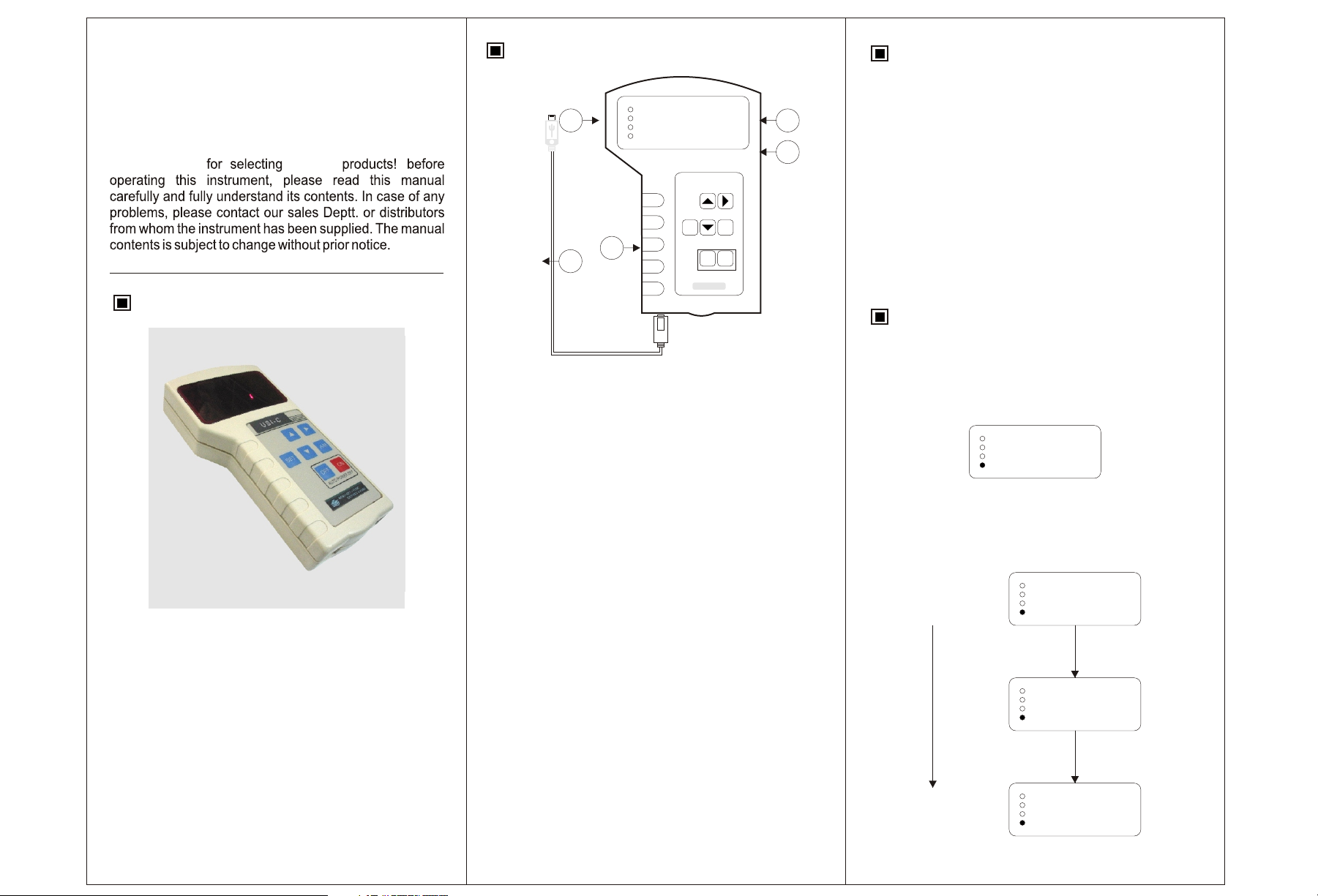
Panel
Communication Process
USI-C Universal Smart Isolator
Hand-Held Configurator
Thank You
ABUSTEK
Introduction
3
8 8 8 8
1
8 8 8 8
2
SET A/M
4
5
1. Measured value (PV) display- It displays PV or various
parameter symbols.
2. Set value (SV) display- It displays SV or various
parameter set values.
3. Indication Lamps
○ => SP1 alarm
○ => SP2 alarm
OFF
AUTO POWER OFF
SPI-C
ON
1. Turn on the power supply of transmitter in right awy.
2. Connect handheld configurator with transmitter by USB
link cable.
3. Press the UP Key of handheld configurator, in order to
start Communication.
4. Once communication is initialized, Communication Lamp
as well as the Power Lamp in the Transmitter will
Flash.
Configuration Process
1. Initialization Mode
After communication is OK, Press SET key
followed by A/M key to enter into Initialization Mode.
S e l
5 5 5
2. Initial Setting Menu
The “SEL” is displayed when the handheld
configurator goes into initialization mode.
USI-C Series Configurator is a handheld configurator for Smart
Programmable Isolator. The new handhelds come with a 2.6
inch (3.6 cm) display having 2 lines with 128 by 128 pixel
resolution. A SET Key function allows the user to scroll a list of
all editable parameters regardless of their position in the
configuration menu structure.
○ => SP3 alarm
○ => Communication lamp
4. Set Key- It is used for parameter calling up and set value
registration.
Up Key- It increase numerals or build communication.
Down Key- It decreases the numerals.
Shift Key- It shifts the digits when settings are changed.
On Key- It is used to Power On the instrument.
Off Key- It is used to Power Off the instrument.
Function Key- It is used to return the previous parameter.
6. USB Data Link cable.
INITIALIZATION MODE
INITIAL SETTING MENU
S e l
5 5 5
Set “SEL” to 101
S e l
1 0 1
Press SET key
I n
0 0
Page 2
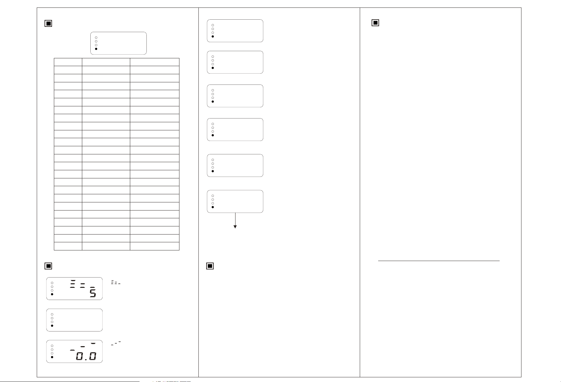
Input Selection (In)
I n
0 0
Set Value
00
01
02
03
04
05
06
07
10
11
12
13
14
15
17
20
21
22
23
24
25
26
27
Input Type
K
E
S
B
J
T
R
N
DC 0~20mV
DC 0~75mV
DC 0~200mV
DC 0~10V
DC 2~20V
DC 0~10mA
DC 4~20mA
Pt100
Cu100
Cu50
BA2
BA1
G
Pt100X
0 ~ 400 Ω
Input Range
0 ~ 1300 °C
0 ~ 900 °C
0 ~ 1600 °C
300 ~ 1800 °C
0 ~ 400 °C
0 ~ 1300 °C
0 ~ 1600 °C
0 ~ 1300 °C
-1999 ~ 9999 °C
-1999 ~ 9999 °C
-1999 ~ 9999 °C
-1999 ~ 9999 °C
-1999 ~ 9999 °C
-1999 ~ 9999 °C
-1999 ~ 9999
-199.9 ~ 600.0 °C
-50.0 ~ 150.0 °C
-50.0 ~ 150.0 °C
-199.9 ~ 600 °C
-199.9 ~ 600 °C
-199.9 ~ 600 °C
-19.99 ~ 99.99 °C
-1999 ~ 9999 °C
L d o
0
L u p
0
O u t
Production value
O d o 1
0
O u p 1
1 3 0 0
E n d
8 0 1
Press Set Key
PV/SV DISPLAY
Ldo
Lup
Out
Odo1
Oup1
End
: Input limiter [LOW] for
input, set scaling within
the input range [low]
(Ldo)
: Input limiter [HIGH] for
input, set scaling within
the input range [HIGH]
(LUP)
: Recommended Settings,
Please don’t change the
values, or it will affect
accuracy.
: Transaction range [Low]
(odo1)
Set “odo1”= “Ldo”
: Transaction range [High]
(ouP1)
Set “ouP1”= “LUP”
: Indicate year and month
of production date (End)
Example: It indicates
production date as
JAN, 2008
Limited Warranty
The products are warranted to be free from defects in
materials and workmanship for a period of one (1) year from
the date of shipment, subject to the following terms and
conditions: Without charge, they will repair, replace, or refund
the purchase price at option products found to be defective in
materials or workmanship within the warranty period;
provided that:
! the product has not been subjected to abuse, neglect,
accident, incorrect wiring not our own, improper installation
or servicing, or use in violation of labels or instructions;
! the product has not been repaired or altered by anyone
except us;
! the maximum ratings label and serial number or date code
have not been removed, defaced, or otherwise changed;
! examination discloses, in the judgment of us, the defect in
materials or workmanship developed under normal
installation, use and service; and
! Our system is notified in advance of and the product is
returned to us transportation prepaid before expiration of
the warranty period.
THIS EXPRESS LIMITED WARRANTY IS IN LIEU OF AND
EXCLUDES ALL OTHER REPRESENTATIONS MADE BY
ADVERTISEMENTS OR BY AGENTS AND ALL OTHER
WARRANTIES, BOTH EXPRESS AND IMPLIED. THERE
ARE NO IMPLIED WARRANTIES OF MERCHANTABILITY
OR OF FITNESS FOR A PARTICULAR PURPOSE FOR
GOODS COVERED HEREUNDER.
Process Parameters Precautions
1. When no parameter setting is required, after the values be
registered, Press “SET” key and “A/M” key simultaneously
to return the instruments to the PV/SV Display.
2. If the displayed value is changed, but not registered, Press
“SET” Key to register the respective value.
D i p
0
: Mode of anti-jamming,
please do not change the
value.
: Decimal Point Position
Dip
(dip)
: PV BIAS, Sensor
correction is made by
adding bias value to
measured value (PV)
Authorised Distributor :
 Loading...