

Page 1
U
SI
ABUS TECHNOLOGIES INC.
New
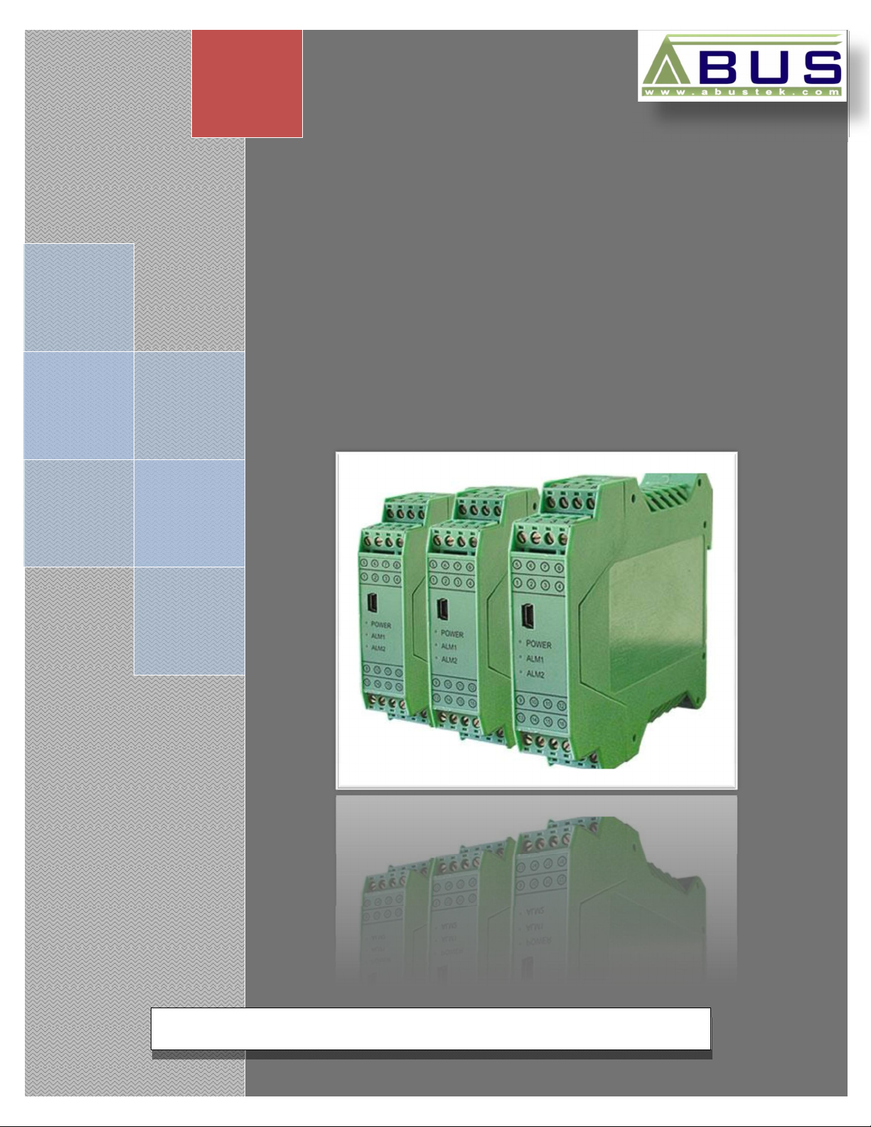
Universal Smart Isolator
User Manual
Page 2

WARNING
This manual should be passed on to the end user.
The contents of this manual are subject to change without prior notice.
All rights reserved.
ABUS gives no warranty of any kind with regard to this manual, including, but not limited to, fitness
for a particular purpose.
If any question arises or errors are found, or if any information is missing from this manual, please
USI
inform your supplier or inform at info@abustek.com
The specifications mentioned in this manual are limited to those for the standard type under the
specified model number break-down and do not necessarily apply for customized instruments.
Please note that changes in the specifications, construction, or component parts of the instrument
may not immediately be reflected in this manual at the time of change.
If the customer or any third party is harmed by the use of this product, ABUS assumes no
responsibility for any such harm owing to any defects in the product which were not predictable, or
for any indirect damages.
Although Warning hazards are related to personal injury, and Caution hazards are associated
with equipment or property damage, it must be understood that operation of damaged equipment could,
under certain operational conditions, result in degraded process system performance leading to
personal injury or death. Therefore, comply fully with all Warning and Caution notices.
Information in this manual is intended only to assist our customers in the efficient operation of
our equipment. Use of this manual for any other purpose is specifically prohibited and its contents are
not to be reproduced in full or part without prior approval of Technical Communications Department,
ABUS Technologies
.
HEALTH AND SAFETY
To ensure that our products are safe and without risk to health, the following points must be
noted:
1. The relevant sections of these instructions must be read carefully before proceeding.
2. Warning labels on containers and packages must be observed.
3. Installation, operation, maintenance and servicing must only be carried out by suitably trained
personnel and in accordance with the information given. Any deviation from these instructions will
transfer the complete liability to the user.
4. Normal safety precautions must be taken to avoid the possibility of an accident occurring when
operating in conditions of high pressure and/or temperature.
5. Chemicals must be stored away from heat, protected from temperature extremes and powders kept
dry. Normal safe handling procedures must be used.
6. When disposing of chemicals ensure that no two chemicals are mixed.
Safety advice concerning the use of the equipment described in this manual or any relevant
hazard data sheets (where applicable) may be obtained from the Company address on the back cover,
together with servicing and spares information.
ABUS TECHNOLOGIES INC.
2
Page 3

9
USI
.
CATALOGUE
Contents Page No.
1. Introduction 4
2. Presentation
1. Features
2. Technical Parameters
3. Dimensions 5
4. Ordering Details
Input Table
5. Connections 8
6. Installation
7. Configuration
8. Operation 9
9. Maintenance
Recommendation
1. Terminal Configuration
2. Single Input Type Configuration
3. Double Input Type Configuration
1. Calibration of Instrument
2. Operation Environment
3. Troubleshooting
4
4
5
6
7
8
9
9
9
10
10
10
10
10. Safety Precautions 11
11. Warranty 11
ABUS TECHNOLOGIES INC.
3
Page 4

1. INTRODUCTION
The ABUS USI Series Universal Smart Isolator being programmable through
Handheld Configurator USI-C can be fit into major of industrial applications operating
with different signals. It can be ordered to accept up to 2 inputs and provide up to 3
outputs. The input signals can be non-linear input such as resistance temperature
detector, thermocouple or linear current or voltage. Signal of one-way, two-way or
three-way current or voltage, isolated by transmitting output provides good electric
isolation between input, output and power. It can be used as a temperature
transmitter, convertor, signal isolator or signal conditioner according to the application.
2. PRESENTATION
2.1 Features
This product uses a special chip. It has many advanced performances which traditional
USI
analogue isolator and many digital isolators don’t possess. This chip provides restrict and process from
software to high/ low-frequency interference signal in input signals. Even in high-power frequency
conversion system it can keep reliable performance. With the help of strong function of this chip
instrument can carry on digitalized automatic/ manual regulation to signal without the help of outside
zero and full-scale potentiometer. Meanwhile it can go on automatic compensation to input signals.
This series of products can also use integrated communication protocol, with the help of the
connection of communicational methods, observing input and output values on line. The integrated
smart isolator using a special chip, besides universal functions, can support the logical process to signal
and set alarm output to condition.
Unique and strong functions of software of the chip and excellent electric performance of
hardware of isolator itself provide firm assurance for stability and reliability of products. And it makes
overall performances of products lead of international advanced standard.
Series of instruments can be used with unit group instruments and DCS, PLC, etc. They are
widely used in all kinds of industries such as oil, chemical, petro-chemical, power, food, steel,
pharmaceutical industries etc...
ABUS TECHNOLOGIES INC.
4
Page 5

2.2 Technical Parameters
Accuracy: ±0.2% FS ± 1 for resistance mVDC VDC and mADC
±0.5% FS ± 1 for thermocouple input.
Output: 0...5 V, 0...10 V, 0.5...4.5 V, 4...20 mA (Customized On
request)
Power Supply: 100~240V AC (50/60Hz, 100~240V AC)
22~26V AC (50/60Hz, 24V AC)
22~26V DC (24V DC).
Isolated Resistance: 10MΩ or more between input and case at DC 550V
10MΩ or more between output and case at DC 550V.
Dielectric Strength: 1000V AC for 1 minute between input terminal and case
1500V AC for 1 minute between output terminal and case.
Load Resistance: DC mA Output
PID O/P: 500Ω
USI
Transmission O/P: 220Ω
VDC Output
Max. Load Current: 20mA
Input Impedance: DC mA Current Input: 200Ω
DC V Voltage Input: 500KΩ
Thermocouple Input: 4.7 KΩ
3. DIMENSIONS
ABUS TECHNOLOGIES INC.
5
Page 6

Linear Signal such as, 4~20mA,
Power
4. ORDERING DETAILS
TYPE DESCRIPTION
USI
Product
Power Supply
Input Type 1
Lower Range 1
Upper Range 1
Input Type 2
Lower Range 2
Upper Range 2
First Output
USI
N AC 90~265V
D DC 24V
C AC 24V
L
0~10V
T Thermocouple or RTD Please Refer Input Table
__
Lower Range : 0 for 0°C
Upper Range : 100 for 100°C
__ Specify Upper Range (Integer value)
N
A Please Refer Input Table
__
__ Specify Upper Range (Integer value)
USI Series Universal Smart Isolator
If None is selected, kindly don’t
specify Range below.
Lower Range : 0 for 0°C
Upper Range : 100 for 100°C
B1
B2 0 – 5 V
B3 0 – 10 mA
Please Refer Input Table
Specify Lower Range (Integer value)
None
Specify Lower Range (Integer value)
4 – 20 mA
Second Output
Third Output
Communication
Auxiliary
Supply
B4 0 – 10 V
Example: USI > D > L > 0 > 100 > N > B1 > C1 > N > M > B
C1
C2 0 – 5 V
C3 0 – 10 mA
C4 0 – 10 V
D1
D2 0 – 5 V
D3 0 – 10 mA
D4 0 – 10 V
N None
N
T RS485
M RS485 (Modbus)
A No AUX power
B AUX 24VDC output
4 – 20 mA
4 – 20 mA
No Communication
ABUS TECHNOLOGIES INC.
6
Page 7

Input Table
SET VALUE INPUT VALUE INPUT RANGE
USI
00
01
02
03
04
05
06
07
10
11
12
13
14
15
K 0~1300 °C
E 0~900 °C
S 0~1600 °C
B 300~1800 °C
J 0 ~ 400 °C
T 0~1300 °C
R 0~1600 °C
N 0~1300 °C
DC 0~20mV -1999~9999 °C
DC 0~75mV -1999~9999 °C
DC 0~200mV -1999~9999 °C
DC 0~10V -1999~9999 °C
DC 2~20V -1999~9999 °C
DC 0~10mA -1999~9999 °C
17
20
21
22
23
24
25
26
27
DC 4~20mA -1999~9999
Pt100 -199.9~600.0 °C
Cu100 -50.0~150.0 °C
Cu50 -50.0~150.0 °C
BA2 -199.9~600 °C
BA1 -199.9~600 °C
G -199.9~600 °C
Pt100X -19.99~99.99 °C
0~400 Ω -1999~9999 °C
ABUS TECHNOLOGIES INC.
7
Page 8

5. CONNECTIONS
USI
1. For thermocouple input, use the specified comenssation wire.
2. For RTD input, use leads with low resistance and having no resistance differences among the 3
leads.
3. Conduct input signal wiring away from instrument power, electric equipment power and loads lines
to avoid noise induction.
4. Conduct instrument power wiring so as not to be influenced by noise from the electric equipment
power. If the instrument is affected by external noise, a noise filter should be used.
a. Shorten the distance between twisted power supply wire pitches. The shorter the distance
between the pitches, more effective is the noise reduction.
b. Install the noise filter on the panel which is always grounded and minimize the wiring distance
between the noise filter output side and the instrument power terminals.
c. Do not install fuses and/or switches on the filter output signal since this may looses filter effect.
5. For wiring, use wires conforming to the domestic standards of the countries.
6. This instruments has no power supply switch for fuses. Therefore, install the fuse close to the
instrument and theswitch, if required.
7. Do not excessively tighten the terminal screws. In addition, use the solderless terminal with respect
to the screw size.
6. INSTALLATION
Recommendation
1. This instrument is intended to be used under the following OVERVOLTAGE CATEGORY II, and
POLLUTION DEGREE 2,
2. Use this instrument within the following ambient temperature and humidity.
a. Temperature: 0~50°C
b. Humidity: 45~85% RH
3. Avoid the following when selecting the mounting location:
a. Rapid changes in ambient temperature which may cause condensation.
b. Corrosive or inflammable gases.
c. Direct vibration or shock to the mainframe,
d. Water, oil, chemicals, vapor or steam splashes.
e. Excessive induction noise, static electricity, magnectic fields or noise
f. Exposure to direct sunlight,
g. Excessive heat accumulation.
ABUS TECHNOLOGIES INC.
8
Page 9

7. CONFIGURATION
7.1 Terminal Configuration
USI
7.2 Single Input Type Configuration
7.3 Double Input Type Configuration
8. OPERATION
For best results, you may use the shielded signal cable to avoid power spikes.
Check all the wires before operating the instrument. Series of instruments can be used
ABUS TECHNOLOGIES INC.
9
Page 10

with instrument for isolation and distribution of signal regarding to your application may
be for recording, controlling through DCS, PLC, etc. They are widely used in all kinds
of industries such as oil, chemical, petro-chemical, power, food, steel, pharmaceutical
industries etc.
S.NO. FUNCTION DESCRIPTION
1 Alarms For indication only.
2 Alarms For indication only
3 Calibration Through Model-1001
9. MAINTENANCE
9.1 Calibration of Instruments
The operation can be realized through ABUS-1001 Operator. The set parameters use the same
USI
calibration way as that of 585 and support automatic calibration.
9.2 Operation Environment
At mounting position strong vibration or strong electromagnetic impact from signal terminal,
power terminal, power terminal and room is not allowed. In operation environment, poisonous or harmful
matters which will corrode metals and plastics are not allowed to exist. Please keep the operation
environment dry for the precise output.
9.3 Troubleshooting
There are two kinds of trouble in input signals: input trouble (open circuit, short circuit) and
beyond span trouble.
Output ways at input trouble: Instruments can select beyond-span gain output and general output.
Gain Output
At the condition of beyond upper limit, output signal has a gain exceeding 5% of normal output
value;
At the condition of beyond lower limit, output signal has an output lower than 5% of lower limit; if
lower limit is zero (i.e.0 ~ 5 V) then output is 0 V.
General Output
At the condition of beyond upper limit, output maximum value or setting value;
At the condition of beyond lower limit, output minimum value or setting value;
At the condition of trouble, keep output value or setting value before output trouble;
Under trouble of input signal, trouble light of instrument flickers to indicate signal trouble.
ABUS TECHNOLOGIES INC.
10
Page 11

10. SAFETY PRECAUTIONS
1. The unit should be powered for 15 minutes before use.
2. Use in ambient temperature of 0-60˚C.
3. Avoid vibrations, shock, excessive dust, corrosive chemical materials or gaseous
environment.
4. Input wire should not be too long. If measured signal have to be far away from the
unit, please use 2-core shielded cable.
5. Use this instrument in the scope of its specifications, otherwise fire or malfunctions
may result.
6. Contact of the instrument, with organic solvents or oils should be avoided.
7. Do not turn on the power supply until all of the wiring is completed. Otherwise
USI
electrical shock, fire or malfunction may result.
8. Do not disassemble, repair or modify the instrument.
9. All connections should be tightened properly.
10. Power supply should be constant, should not be fluctuating.
11. WARRANTY
ABUS provides the original purchaser of this instrument a one (1) year warranty
against defects in material and workmanship under the following terms:
The one year warranty begins on the day of shipment as stated on the sales bill.
During the warranty period all costs of material and labor will be free of charge
provided that the instrument does not show any evidence of misuse.
For maintenance, return the instrument with a copy of the sales bill to our factory.
All transportation and insurance costs should be covered by the owner of the
equipment.
Should any sign of electrical or mechanical shock, abuse, bad handling or misuse
be evident the warranty voids and maintenance costs will be charged.
ABUS TECHNOLOGIES INC.
www.abustek.com, E-M ail: info@abustek.com
ABUS TECHNOLOGIES INC.
11
 Loading...