

Page 1
UC
Series
ABUS TECHNOLOGIES INC.
Universal Process Controller
User Manual
Page 2

WARNING
This manual should be passed on to the end user.
The contents of this manual are subject to change without prior notice.
All rights reserved.
ABUS gives no warranty of any kind with regard to this manual, including, but not limited to, fitness
for a particular purpose.
If any question arises or errors are found, or if any information is missing from this manual, please
UC
inform your supplier or inform at info@abustek.com
.
The specifications mentioned in this manual are limited to those for the standard type under the
specified model number break-down and do not necessarily apply for customized instruments.
Please note that changes in the specifications, construction, or component parts of the instrument
may not immediately be reflected in this manual at the time of change.
If the customer or any third party is harmed by the use of this product, ABUS assumes no
responsibility for any such harm owing to any defects in the product which were not predictable, or
for any indirect damages.
Although Warning hazards are related to personal injury, and Caution hazards are associated
with equipment or property damage, it must be understood that operation of damaged equipment could,
under certain operational conditions, result in degraded process system performance leading to
personal injury or death. Therefore, comply fully with all Warning and Caution notices.
Information in this manual is intended only to assist our customers in the efficient operation of
our equipment. Use of this manual for any other purpose is specifically prohibited and its contents are
not to be reproduced in full or part without prior approval of Technical Communications Department,
ABUS Technologies
HEALTH AND SAFETY
To ensure that our products are safe and without risk to health, the following points must be
noted:
1. The relevant sections of these instructions must be read carefully before proceeding.
2. Warning labels on containers and packages must be observed.
3. Installation, operation, maintenance and servicing must only be carried out by suitably trained
personnel and in accordance with the information given. Any deviation from these instructions will
transfer the complete liability to the user.
4. Normal safety precautions must be taken to avoid the possibility of an accident occurring when
operating in conditions of high pressure and/or temperature.
5. Chemicals must be stored away from heat, protected from temperature extremes and powders kept
dry. Normal safe handling procedures must be used.
6. When disposing of chemicals ensure that no two chemicals are mixed.
Safety advice concerning the use of the equipment described in this manual or any relevant hazard data
sheets (where applicable) may be obtained from the Company address on the back cover, together with
servicing and spares information.
ABUS TECHNOLOGIES INC.
2
Page 3

.
UC
CATALOGUE
Contents Page No.
1. Introduction 4
2. Presentation
1. Features
Technical Parameters
2.
Display status
3.
3. Dimensions 5
4. Ordering Details 5
5. Connections 6
6. Installation
1. Input Signal
Panel
2.
7. Configuration
1. Configuration Process
Key Operation Instructions
2.
8. Maintenance 9
9. Safety Precautions 10
10. Warranty 10
4
4
4
5
7
7
7
8
8
9
ABUS TECHNOLOGIES INC.
3
Page 4

1. INTRODUCTION
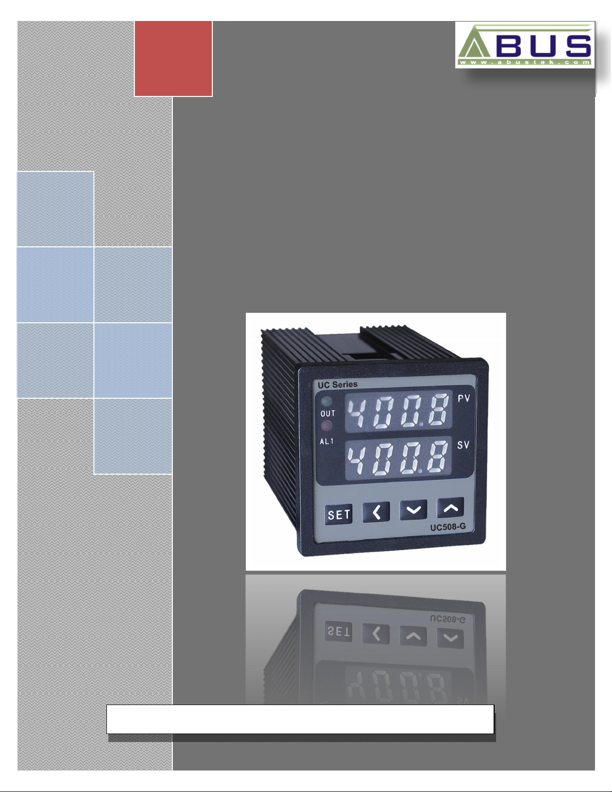
UC508 economy is a Microprocessor based Digital Process Controller, which
can be applied in high-precision measurement and control of temperature, pressure,
discharge, liquid level and humidity etc... A four-digit LCD dual display shows
measured value and set-value for all programming parameters. Instrument
configuration is achieved from the front panel keyboard, without any hardware change.
The user should read this manual thoroughly before using the instrument. It must be
handled with care and should be used accordingly for best results.
2. PRESENTATION
2.1 Features
1. Input signal: Thermocouple, RTD, direct voltage, current programmed from the front panel.
2. Outputs can be set on-off control or PID control with configurable direct/reverse action modes.
3. The input uses digital correction system; there is nonlinear correction form of communal used
thermocouple and resistance thermometer detector.
4. Control output modes hold out relay contact switch, solid-state relay driving voltage, and singlephase thyristor zero-crossing trigger signal etc.
5. Comprehensive self-detection and protection. In case of error, it provides automatic repair or
prompt message and closes the output.
2.2 Technical Parameters
Input Signals: Refer to table 6.1 Input Signal
Intrinsic error: ± 0.5% FS ± 1 digit
Sampling period: <0.3s
Working power supply: 220V 10%/50~60Hz, power consumption<5W.
Control modes (freely changeable with keypad):
On-off control (configurable direct/reverse action and differential gap)
PID control (configurable direct/reverse action, manual or automatic of PID parameters)
Alarm modes (freely changeable with keypad):
One way of programmable alarm output is provided with a number of alarm modes including
higher limit, lower limit (Relay output).
In addition, the alarm feature can also be temporarily disabled when applying the power.
Output specifications:
Output module of relay contact switch: Normally open (absorbed by varistor), 30VDC/2A,
240VAC/2A.
Output module of solid-state relay (SSR) driving voltage: 12VDC/25mA.
Output module of single-phase thyristor zero-crossing trigger signal: 100~380VAC/50~60Hz,
capable of triggering
5-500A TRIAC or 2 SCRs in inverse parallel connection or thyristor power module.
Operating Environment:
Recommended Temperature: 0~50
Relative Humidity: ≤ 85%RH
UC
ABUS TECHNOLOGIES INC.
4
Page 5

HOLE
2.3 Display Status
UC
3. DIMENSIONS
PANEL
DIMENSION
CODE
A 96 96 91 91 100 92 92
D 72 72 67 67 100 68 68
E 48 96 44 90 100 45 92
F 96 48 90 44 100 92 45
G 48 48 44 44 100 45 45
4. ORDERING DETAILS
TYPE DESCRIPTION
Product
UC508 UC Series Process Controller
A
PANEL
DIMENSION
CASE DIMENSION
CUTOUT
DIMENSION
W H W H D W H
96 x 96 mm
Dimensions
Control Output
Alarm Output
Input type
RS#485
Communication
D 72 x 72 mm
E 48 x 96 mm
F 96 x 48 mm
G 48 x 48 mm
2
4 Solid-state relay driving voltage output.
Relay contact switch output.
6 SCR Single-phase thyristor
0
None
1 1-Alarm.
0
Universal (Refer table 6.1)
No communication
0
With RS485 Modbus RTU Protocol.
1
Example: UC508 > G > 2 > 1 > 0 > 1
ABUS TECHNOLOGIES INC.
5
Page 6

Wiring Diagram of UC
Series
-
A.E.F
Wiring Diagram of UC Series
-G
Wiring Diagram of UC Series
-D
Wiring diagram of thyristor trigger output
5. CONNECTIONS
UC
Description of symbols in the wiring diagram
SYMBOLS
OUT Alarm Outlet
ALARM Control Outlet
RELAY Relay contact switch Output
SSR Solid-state relay driving Voltage Output.
SCR
I Direct current Input
TC/U Thermocouple / Direct Voltage Input
RTD RTD Input
Thyristor zero-crossing trigger signal
Output
DESCRIPTION
ABUS TECHNOLOGIES INC.
6
Page 7

6. INSTALLATION
6.1 Input Signal
INPUT TYPE CODE MEASURING RANGE
K -50°C ~ +1350°C
UC
Resistance Thermometer
6.2 Panel
Thermocouple
(TC)
Detector
(RTD)
Direct voltage
(V)
Direct Current
(I)
S -50°C ~ +1750°C
E -50°C ~ +800°C
J -50°C ~ +1000°C
Cu50 -50°C ~ +150°C
Pt100 -200°C ~ +850°C
0-5V
1-5V
0-20mA
Customized range within
-1999 ~ +9999
4-20mA
ABUS TECHNOLOGIES INC.
7
Page 8

7. CONFIGURATION
7.1 Configuration Process
UC
ABUS TECHNOLOGIES INC.
8
Page 9

7.2 Key Operation Instruction
power. The PV screen and the SV screen will display process value and set value
respectively.
Parameter setting block: Under PV/SV display block, the instrument will enter
parameter setting block by pressing down SET key for 2s. The PV screen displays
parameter name and the SV screen displays parameter value, the last figure of which
will flash. Edit parameter value with ◄, ▼, ▲ keys. Then press SET key to confirm the
change and switch to the next parameter name, or press down SET key for 2s to
confirm the change and return to PV/SV display block. The instrument will return to
The instrument will automatically enter PV/SV display block 3.5s after applying
UC
PV/SV display block if there is no key action for 60s, in this case, the last change to
the parameter will be cancelled.
Self-tuning block (only available when LOC=0 and the instrument are under PID
control mode): Under PV/SV display block, the instrument will enter self-tuning block
by pressing down key for 2s. The PV screen displays the process value, and the SV
screen displays a flashing -At- at interval of 0.5s (during the process, the instrument
can enter and exit parameter setting block and output display block with no effect on
self-tuning. But the self-tuning prompt will disappear). On completion of self-tuning, the
PID parameters of the instrument will be automatically changed and saved and the
instrument will return to PV/SV display block automatically. Press down ▼ key for 2s
when -At- on the SV screen stops flashing to exit the self-tuning block during self-
tuning process.
8. MAINTENANCE
Metrological verification should be conducted annually for the instrument. If the
instrument goes beyond error limit, which often results from a damper environment,
dust or corrosive gas, the inner part of the instrument should be cleaned and dried. In
case the accuracy can not be restored by cleaning and drying, the instrument should
be sent back as default product to the factory for troubleshooting.
ABUS TECHNOLOGIES INC.
9
Page 10

9. SAFETY PRECAUTIONS
1. The unit should be powered for 15 minutes before use.
2. Use in ambient temperature of 0-60˚C.
3. Avoid vibrations, shock, excessive dust, corrosive chemical materials or gaseous
environment.
4. Input wire should not be too long. If measured signal have to be far away from the
unit, please use 2-core shielded cable.
5. Use this instrument in the scope of its specifications, otherwise fire or malfunctions
may result.
6. Contact of the instrument, with organic solvents or oils should be avoided.
7. Do not turn on the power supply until all of the wiring is completed. Otherwise
UC
electrical shock, fire or malfunction may result.
8. Do not disassemble, repair or modify the instrument.
9. All connections should be tightened properly.
10. Power supply should be constant, should not be fluctuating.
10. WARRANTY
ABUS provides the original purchaser of this instrument a one (1) year warranty
against defects in material and workmanship under the following terms:
The one year warranty begins on the day of shipment as stated on the sales bill.
During the warranty period all costs of material and labor will be free of charge
provided that the instrument does not show any evidence of misuse.
For maintenance, return the instrument with a copy of the sales bill to our factory.
All transportation and insurance costs should be covered by the owner of the
equipment.
Should any sign of electrical or mechanical shock, abuse, bad handling or misuse
be evident the warranty voids and maintenance costs will be charged.
ABUS TECHNOLOGIES INC.
www.abustek.com, E-M ail: info@abustek.com
ABUS TECHNOLOGIES INC.
10
 Loading...