

Page 1
P
e
u
T
n
j
å
d
o
t
B
ł
o
TVI
1000
Us
5B /
r ma
VIP1
ual
0055
Version
03/2013
E
Ins
Br
Ma
trukc
gerh
nual
a obs
ndb
e ins
ugi
g
rucci
nes
1
Page 2

These user manual contains important information for installation and operation.
This should be noted also when this product is passed on to a third party.
Therefore look after these operating instructions for future reference!
A list of contents with the corresponding page numbers can be found in the index on page 6.
Niniejsza instrukcja obsługi zawiera ważne wskazówki dotyczące uruchamiania i obsługi. Pamiętaj
o tym, także przekazując produkt osobie trzeciej.
Zachowaj instrukcję do wykorzystania w przyszłości!
Wykaz treści znajdziesz w spisie treści z podaniem odpowiednich liczb stron na stronie 35.
Denne manual hører sammen med dette produkt. Den indeholder vigtig information som skal
bruges under opsætning og efterfølgende ved service. Dette skal huskes også når produkter
gives videre til anden part.
Læs derfor denne manual grundigt igennem også for fremtiden.
Indholdet kan ses med sideanvisninger kan findes i indekset på side 66.
E
Este manual de instrucciones contiene indicaciones importantes para el manejo y la puesta en
funcionamiento del producto. Téngalas también en cuenta si entrega la máquina a terceros.
Por ello, consérvelas en un lugar adecuado para su posterior lectura.
En el índice de la página 96 encontrará un listado de los contenidos con las páginas donde podrá
consultarlos.
2
Page 3
VGA
p
A
t
C
k
u
Com
Ne
act
wor
ame
ra
Version
03/2013
User
man
al
3
Page 4

n
s
o
r
a
n
s
p
s
a
s
B
a
m
a
i
s
g
n
n
p
.
e
e
w
a
t
s
o
t
t
p
o
t
m
e
G
m
r
e
f
o
s
m
o
a
a
a
e
t
u
c
c
e
r
s
s
a
m
o
a
r
k
a
u
n
d
n
r
e
s
d
m
n
n
f
u
f
e
a
e
p
c
e
l
I
Dear Cu
Thank y
This pro
The cor
To maint
operatio
Before in
safety in
All com
All right
If you h
troduct
tomer,
u for purch
duct meet
espondin
in this co
instructio
itial start-u
tructions.
any and p
reserved
ve any qu
on
asing this
the requi
declarati
dition and
s!
, read thro
roduct na
stions, pl
roduct.
rements o
ns and d
o ensure ri
ugh the co
es menti
ase cont
the appli
cuments
k-free op
plete ope
ned in thi
ct your in
able Euro
an be obt
ration, you
ating instr
docume
taller or y
ean and
ined from
as the use
ctions obs
t are regi
ur local
ational g
the manu
must obs
rving oper
tered trad
ealer!
idelines.
acturer.
rve these
ting and
marks.
This u
please
The A
faults
without
The co
caused
No gu
Disclaim
er manual
inform us
US Securi
nd reserve
a previous
pany is n
in connec
rantee for
as prepar
bout these
y-Center
the right t
announce
t liable or
ion with th
he content
d with gre
on the bac
mbH & Co.
make at
ent.
esponsibl
equipmen
of this doc
atest care.
k of this m
KG assu
ny time m
for direct
t, the perfo
ment is ta
If you shou
nual given
es no liabil
difications
nd indirect
mance an
en.
ld notice o
address.
ity for tech
to the prod
subseque
the use o
issions or
ical and ty
uct or user
t damages
this produ
inaccuraci
ographica
manual
which are
t.
s,
4
Page 5
t
w
c
h(C
h
h
eus A
n
e
x
u
e
a
o
o
opa
l
s
l
l
l
e
t
n
n
p
g
w
a
d
e
x
o
t
u
o
t
h
p
e
e
t
v
e
e
e
c
t
h
o
e
h
o
s
a
g
n
h
o
h
s
c
s
s
c
o
e
a
r
s
n
e
f
n
s
a
d
w
d
r
a
a
l
e
a
s
f
d
e
h
f
a
r
g
h
e
h
t
p
e
y
o
i
o
o
a
v
c
d
m
e
s
t
u
m
o
e
p
y
e
p
o
i
b
e
c
o
a
i
t
d
e
y
e
s
h
j
h
o
l
A
a
a
s
o
a
e
e
e
a
r
A
h
t
a
s
e
e
w
d
n
o
t
t
c
w
r
c
e
d
Importa
Dear cus
The follo
the prote
T
T
T
D
s
nt safety
The wa
instruc
We do
handli
expire.
omer,
ing safety
tion of the
ere are no
E) and the
e product
is device c
uring the ins
nsor of the
er manual.
instructio
rranty will
ions. We s
ot accept l
g or non-c
instruction
device. Ple
arts on the
uarantee/w
ill be dama
n be used i
tallation of t
evice. Plea
ns
xpire for d
all not be l
iability for
mpliance
are inten
se read th
inside of the
rranty will l
ed even it f
inside only
e camera p
e follow th
mage due
iable for an
amage to
ith the saf
ed not onl
ough the f
product wh
pse if you
lls from a l
.
lease take c
installation
o non-com
consequ
roperty or
ty-instructi
for the pr
llowing po
ch need to
pen/take th
w height.
re that dire
instructions
liance wit
ntial loss!
ersonal in
ns. In suc
tection of y
nts careful
e serviced.
product ap
t sunlight c
in the corre
these ope
ury caused
cases the
our health,
y:
part from t
rt.
nnot fall on
ponding ch
ating
by incorre
warranty
but also fo
is, the licen
o the image
pter of this
t
ill
se
void usi
w
e
di
d
st
st
th
the s
th
General s
D
F
P
U
P
C
P
g the devic
tness or e
treme cold
rect sunligh
st or comb
rong vibrati
rong magne
e camera s
nsor.
e camera m
afety instruc
not leave
c
uld becom
r safety rea
rts.
ease do not
e only acc
P
ease do not
ease pay at
heck the de
ease adher
d
stroy the d
During th
disconne
under the f
cessive air
r heat
stible gase
n
ic fields, su
ould not po
ay not be in
tions:
ackaging m
dangerous
sons don’t g
insert objec
ssories whi
connect inc
ention to th
ice for dam
to the ope
vice and po
installatio
ted from th
llowing unf
umidity
, vapors or
h as those
itioned with
talled on un
aterial lying
oys for chil
ive the cam
s through t
h are speci
mpatible p
safety inst
ges before
ational volta
e a health
into an exis
low and su
vorable am
olvents
ound in the
opened iris
stable surfa
around care
ren.
ra into chil
e openings
ied by the
rts to the d
uctions and
installation.
ge limitation
azard (elec
ting video s
pply voltage
bient conditi
icinity of m
owards the
es
lessly. Plast
hands due
into the devi
anufacturer.
vice.
user manua
If this shoul
listed in th
ric shock).
rveillance s
circuit.
ns:
chinery or l
sun - this ca
c/ foil/bags
o them bein
e.
ls of the oth
be the cas
technical d
stem make
udspeaker
n lead to th
nd polystyr
g able to s
r connecte
please do
ata. High v
sure that all
destruction
ne parts et
allow small
devices.
ot use it.
ltage could
devices are
of
.
If in doub
make-do
persons.
Wire-up t
and cann
allow a pro
electrical co
e entire sy
t come into
essional el
nection to t
tem making
contact wit
ctrician to
he mains d
sure that th
each other
5
ount, install
es only repr
mains and
in normal u
and wire-up
sent at thr
low voltage
e or due to
your device
at to you bu
circuit rema
ny malfunc
. Improper o
also to oth
in separate
ioning.
r
r
Page 6

Contents
1. Usage in accordance with regulations ................................................................................. 7
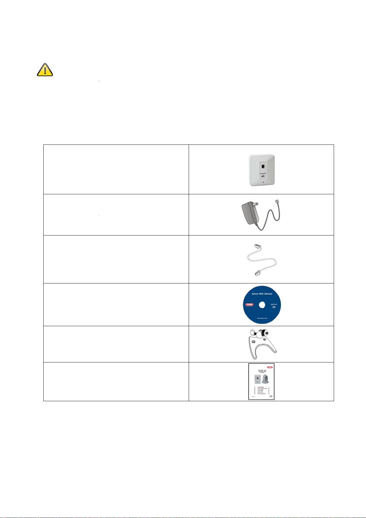
2. Scope of delivery .................................................................................................................... 7
3. Installation ............................................................................................................................... 8
3.1 Power supply .......................................................................................................................... 8
3.2 Installing the camera .............................................................................................................. 8
4. Camera description ................................................................................................................ 8
4.1 Description of connectors ..................................................................................................... 8
4.2 Status LEDs ............................................................................................................................. 9
4.3 Restoring the factory settings ............................................................................................... 9
4.4 Putting into operation .......................................................................................................... 10
4.5 Accessing the network camera for the first time ............................................................... 11
4.6 Accessing the network camera over a web browser......................................................... 12
4.7 Installing the ActiveX plug-in .............................................................................................. 12
4.8 Adjusting the security settings ........................................................................................... 12
4.9 Password prompt ................................................................................................................. 13
5. User functions ....................................................................................................................... 14
5.1. Video control ......................................................................................................................... 15
6. Camera settings (configuration) ......................................................................................... 17
6.1 System ................................................................................................................................... 18
6.2 Video ...................................................................................................................................... 21
6.3 Audio ...................................................................................................................................... 21
Network .................................................................................................................................. 22
6.4
6.5 Security .................................................................................................................................. 27
7. Maintenance and cleaning ................................................................................................... 28
7.1 Function test ......................................................................................................................... 28
7.2 Cleaning ................................................................................................................................. 28
8. Disposal ................................................................................................................................. 28
9. Technical data ....................................................................................................................... 29
10. GPL license information ...................................................................................................... 30
6
Page 7
g
p
o
h
o
o
e
g
v
ABUS
o
o
S
n
o
A
o
a
a
n
a
u
m
D
c
t
n
n
l
t
e
a
e
t
m
w
b
d
u
p
h
u
s
o
1. Usa
2. Sco
e in acc
Use of t
and othe
invalidati
This als
Read th
operatin
e of deli
TVIP10
rdance w
is product f
r dangers.
n of the pr
applies to
entire oper
manual co
ery
network c
005B / TVIP
P
wer supply
ith regula
r other than
ll other uses
duct guara
ny alteratio
ting manua
tains impor
mera
10055B
nit
tions
the describ
are not in a
tee and war
s or modific
l carefully b
ant informa
d purpose
ccordance
ranty. No lia
tions made
fore putting
ion on instal
ay lead to
ith regulatio
ility can be
to the prod
the product
ation and o
amage to t
ns, and res
accepted a
ct.
into operati
eration.
e product
lt in the
a result.
n. The
Netw
(includi
Wa
rk cable (1
oftware C
g operating
ll mount bra
Quick guide
etre)
manual)
ket
7
Page 8
3. Installation
Make sure that all accessories and parts listed above are present in the scope of delivery. An Ethernet cable
is required for camera operation. This Ethernet cable must meet UTP Category 5 (CAT 5) specifications and
must not be longer than 100 metres.
3.1 Power supply
Before starting installation, ensure that the mains voltage and the rated voltage on the power supply unit are
identical. The camera’s supply voltage is 5 VDC. Please use the supplied power supply
3.2 Installing the camera
With the camera a mounting bracket is supplied. At the backside of the camera a socket is located. Using this
socket the camera mounting bracket can be fixed at the camera. The mounting bracket can be fixed at the
wall unsing the supplied pegs and screws.
4. Camera description
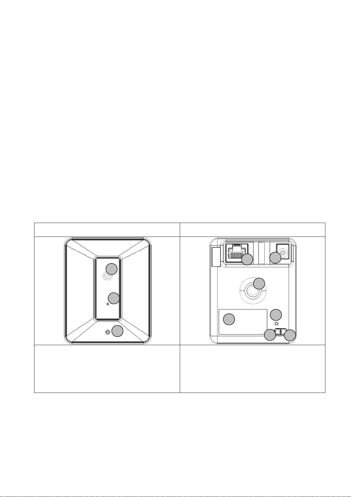
4.1 Description of connectors
Front side Back side
1
2
3
1 Lens
2 Microphone
3 Status LED
4 Network connector
5 Power supply connector 5 VDC
6 WPS Status LED (only TVIP10055B)
4
5
9
7
6
8
a
7 WPS button (only TVIP10055B)
8 Reset button
9 Socket for camera bracket (1/4 inch
thread)
a Product sticker (with model number and
MAC address)
8
Page 9

4.2 Status LEDs
LED Farbe Bedeutung
Status LED Red continuously on Start up procedure (boot procedure)
In case a network cable is attached to the
camera, the camera will try to assign a valid IP
address (using DHCP or using the configured
fixed IP address).
In case wireless network is configured, the
camera tries to connect to access point using
the configured wireless SSID/encryption.
Red flashing 1 /
second
Blue continuously on IP address was assigned successfully. (Note: it
WPS LED Flashing 1 / second WPS search started (pressing the WPS button
Network connection is not available.
LAN: network cable not connected or defect
Wireless: configured wireless data is not
accepted by the access point, or the access
point is out of range.
could be possible that the IP address will not
match the target network. This can happen on
manual setting of IP address.
for more than 10 seconds). The camera will try
to exchange the wireless encryption settings
with the WPS activated access point/Router.
4.3 Restoring the factory settings
Camera restart Press the reset button for a short time. The camera will
reboot.
Restoring the factory settings Press the reset button for more than 10 seconds. The
settings of the camera will be reset to factory default.
This is especially required after a firmware upgrade.
9
Page 10
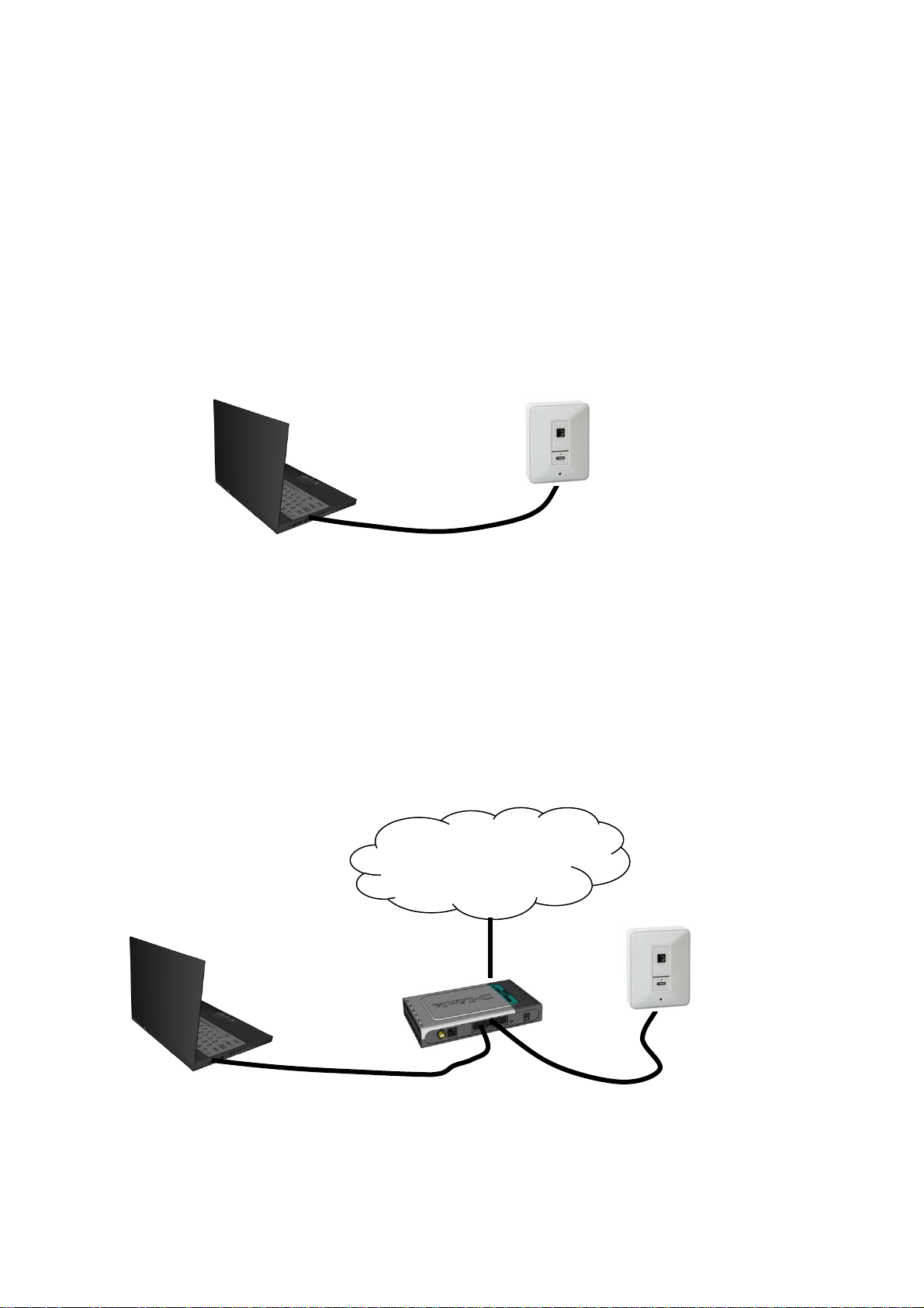
4.4 Putting into operation
The network camera automatically detects whether a direct connection between the PC and camera should
be made. A cross-over network cable is not required for this. You can use the supplied patch cable for direct
connection when putting into operation for the first time.
Direct connection of the network camera to a PC / laptop
1. Ensure that a CAT 5 network cable is used.
2. Connect the cable to the Ethernet interface of the PC / laptop and the network camera.
3. Connect the power supply to the network camera.
4. Configure the network interface of your PC / laptop to the IP address 192.168.1.1 and the default
gateway to 192.168.1.2.
5. Go to point 4.6 to finish the initial set-up and establish the connection to the network camera.
CAT 5 Ethernet cable
Connecting the network camera to a router / switch
1. Ensure that a CAT 5 network cable is used.
2. Connect the PC / laptop to the router / switch.
3. Connect the network camera to the router / switch.
4. Connect the power supply to the network camera.
5. If a DHCP server is available in your network, set the network interface of your PC / laptop to
“Obtain an IP address automatically”.
6. If no DHCP server is available, configure the network interface of your PC / laptop to 192.168.1.1
and the default gateway to 192.168.1.2.
7. Go to point 4.6 to finish the initial set-up and establish the connection to the network camera.
8.
Internet
10
Page 11
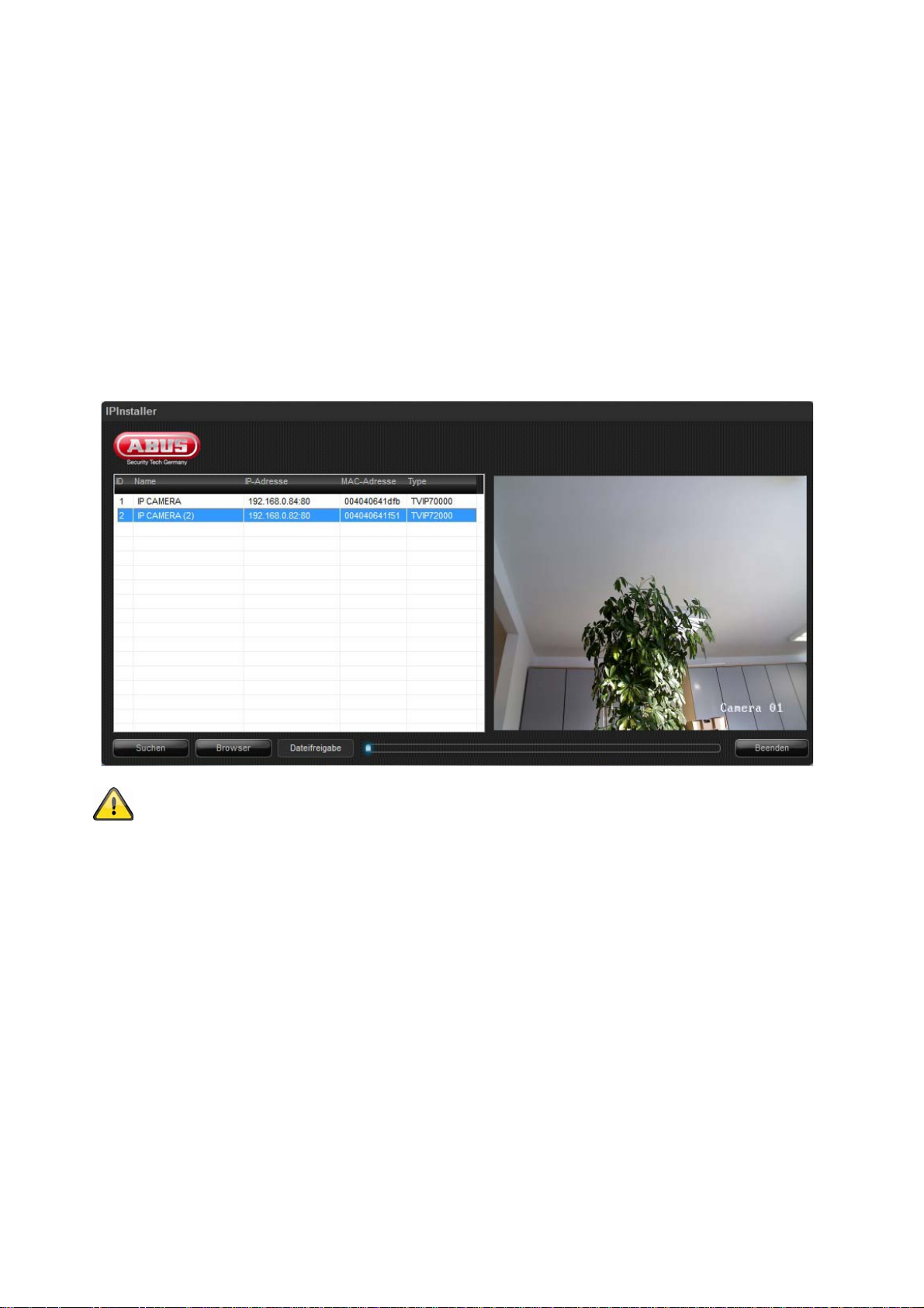
4.5 Accessing the network camera for the first time
The network camera is accessed for the first time using the IP Installer.
After the installation wizard is started, it searches for all connected ABUS IP network cameras and video
servers in your network.
The program is found on the supplied CD-ROM. Install the program on your PC and then run it.
If a DHCP server is available in your network, the IP address is assigned automatically for both the PC /
laptop and the network camera.
If no DHCP server is available, the network camera determines a free IP address from the 192.168.1.2–
192.168.1.254 range independently. Your PC system must be located in the same IP segment in order to
establish communications with the network camera.
The standard setting for the network camera is “DHCP”. If no DHCP server is in operation in
your network, then we recommend setting the IP address manually to a fixed value following
initial access to the network camera.
11
Page 12
e
u
A
e
n
a
a
u
e
s
e
A
F
b
u
o
A
o
k
m
C
e
u
l
e
r
s
y
e
d
v
d
o
o
a
o
b
s
d
c
a
t
r
e
.
h
m
e
e
y
u
b
s
a
c
k
v
o
t
s
e
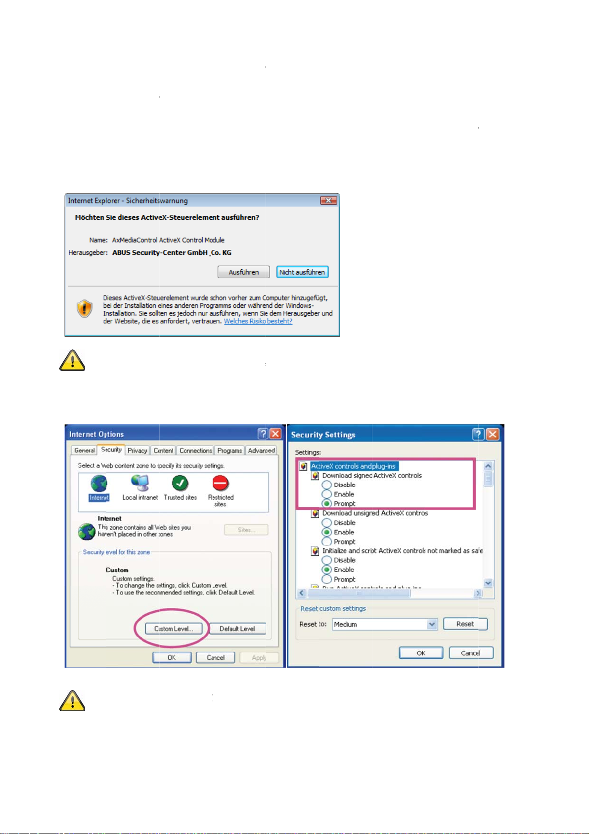
4.6 Acc
When yo
ctiveX pl
highest s
used for d
installatio
administr
4.7 Inst
ssing th
first acces
ug-in for the
curity level i
isplaying th
, open the I
tor.
lling the
If Mozilla
provided
network
the networ
network ca
s set, the P
video in th
nternet sec
ctiveX p
irefox is us
y the came
camera o
camera un
era. This q
will refuse
browser. T
rity settings
ug-in
d as the br
a instead of
ver a we
er Window
uery depen
any installat
continue,
and reduce
wser when
the ActiveX
browser
, the web b
s on the Int
on and any
lick “Install”
the security
accessing t
plug-in.
wser queri
rnet securit
ttempt at r
If the web
level or con
e camera,
s the install
settings of
nning it. Thi
rowser pre
ult your IT
n MJPEG s
ation of an
your PC. If t
s plug-in is
ents the
r network
ream is
he
4.8 Adj
sting the
Note: Yo
settings t
ctiveX c
security
r PC securit
a lower lev
ntrols and
ettings
settings m
l under “To
ownloads.
y prevent
ls / Interne
video strea
Options / S
. You can
curity”. Ma
hange the
e sure you
ecurity
nable
12
Page 13
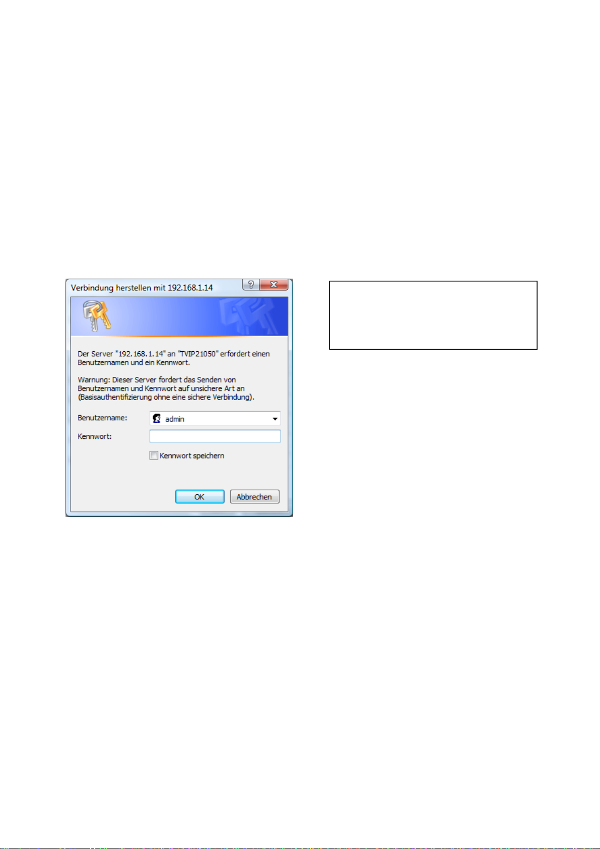
4.9 Password prompt
An administrator password is defined in the network camera as standard. However, the administrator should
define a new password immediately for security reasons. After the new administrator password is stored, the
network camera asks for the user name and password every time it is accessed.
The administrator account is set up in the factory as follows: user name “admin” and password “12345”. Each
time the network camera is accessed, the browser displays an authentication window and asks for the user
name and password. If you can no longer access your personal settings in the administrator account, you can
log in again with user name “admin” and password “12345” after resetting the network camera to the factory
settings.
To enter a user name and password, proceed as follows:
Open Internet Explorer and enter the IP address of the camera (e.g. “http://192.168.1.14”).
You are then prompted for authentication:
Standard user name: admin
Standard password: 12345
-> You are now connected with the network camera and can see a video stream.
13
Page 14
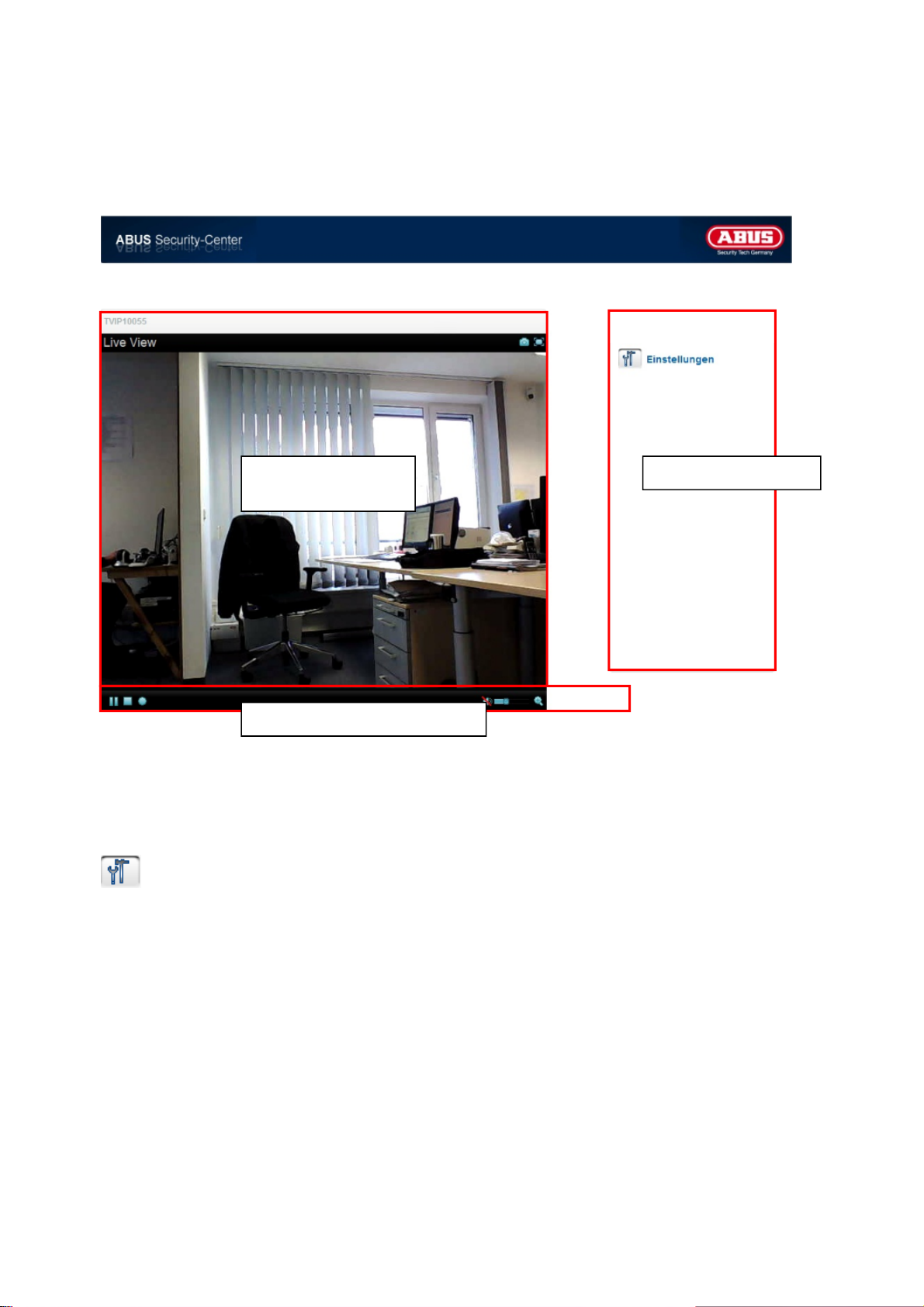
5. User functions
Open the main menu on the network camera. The interface is divided into the following main areas:
Live image
Camera settings
display
Live image display
You can access the full-screen view by double-clicking here (with Internet Explorer only).
Camera settings
Settings (configuration)
Used to configure the camera (administrator settings)
Video control
14
Page 15
5.1. Video control
These functions are only available when using Internet Explorer.
The web browser displays a new window containing the snapshot. To save the snapshot, either left-click it
and then click the floppy disk icon or right-click it and select “Save” from the context menu.
Activate the full-screen view. The live image on the network camera is shown on the entire screen.
The live stream can be stopped or ended. In both cases you can continue the live stream by pressing the play
symbol.
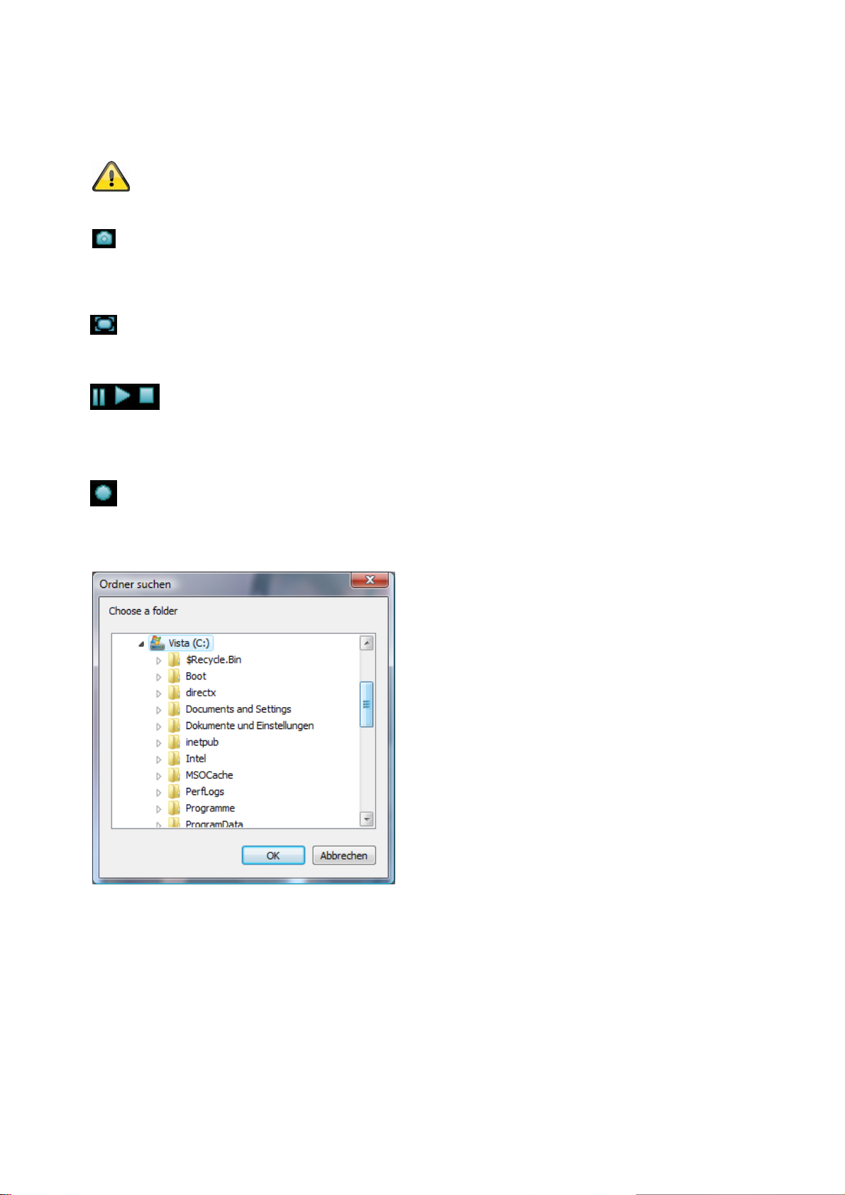
A recording on the local hard drive can be started or stopped. If you click the button, the Windows “Save as”
dialog is called up.
Snapshot
Full-screen view
Local recording
Start/stop live image display
Select a target directory on your hard drive. A directory and recording file are created automatically in the
folder under the following name:
YYYYMMDD
YYYYMMDDHHmmss.avi
Y = Year
M = Month
D = Day
H = Hour
m = Minute
s = Second
15
Page 16

Example:
C:\Recording\20091215\20091215143010.avi
The recorded data can be played back using an MP4-compatible video player (e.g. VLC Media
Click the magnifying glass symbol to activate the digital zoom. The zoom factor can be changed on the scroll
bar.
Player). Alternatively, you can also watch the videos on Windows Media Player by installing a
video codec in the IP Installer.
Digital zoom
Setting the zoom factor
Change the zoom factor by moving the bar from left (low zoom) to right (high zoom).
16
Page 17
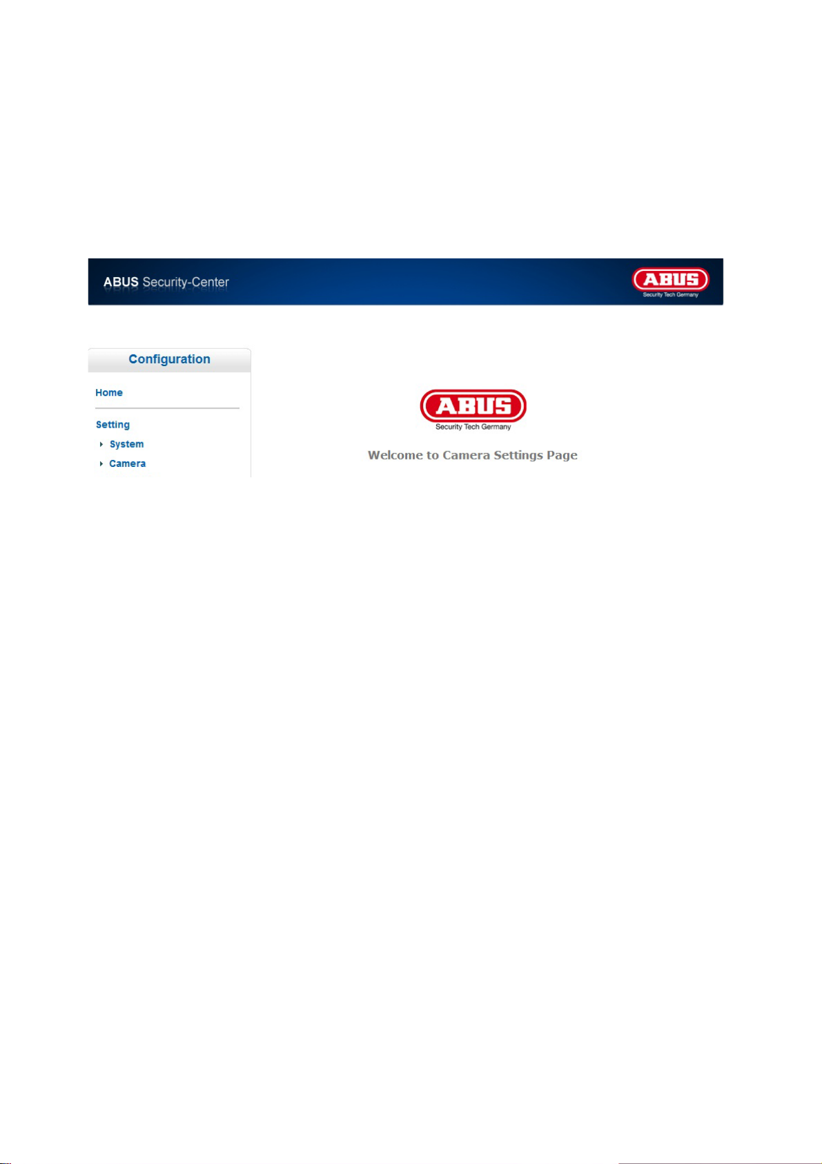
6. Camera settings (configuration)
Only the administrator has access to the system configuration. The following sections explain each of the
elements in the left-hand column. After you click a menu item on the left-hand side, a menu tree may be
opened depending on the number of sub-items contained in the item. In this case, continue by clicking the
sub-item.
Click “Home” to return to the main camera page.
17
Page 18

6.1 System
Information
Product information:
Product name: The product name indicates the functions included (e.g. WLAN).
Current version: Shows the current version of the installed firmware.
Image settings:
Brightness: Shows current brightness value
Contrast: Shows current contrast value
Saturation: Shows current saturation value
Sharpness: Shows current sharpness value
White balance: Selected option for white balance
Network:
LAN status: Current used IP addess and HTTP port
Wireless status: Information about current wireless settings (only TVIP10055B)
Information
LED: Activate or deactivate the status LED at the front side of camera.
Hostname
Camera name: This is the description of the camera inside the network. As default the item number is
configured.
18
Page 19
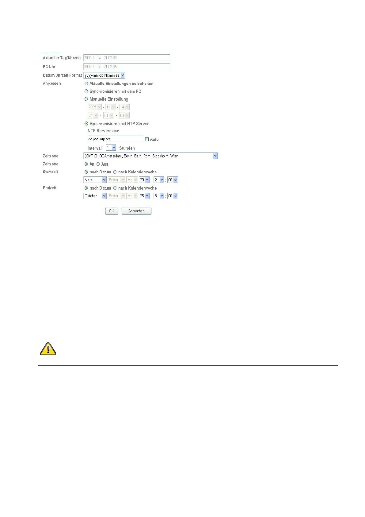
Date/time
Current date/time:
PC clock: Shows the date/time on the PC from which you access the camera.
Date/time format:
Adjust:
Keep current settings:
Synchronize with the PC:
Manual setting: Manually set the time and date here.
Synchronize with the NTP server: Automatic updating of the date and time via a time server (Network
NTP server name:
Auto: When activated, the standard time server is used. Deactivate the “Auto”
Interval:
Time zone: Here you select the time zone in which the camera is located.
Daylight savings time:
Updating interval with the time server in hours
Shows the setting for the date/time currently stored in the camera.
Select a format (YYYY-year, MM-month, DD-day, hh-our, mm-minute, ss-second).
No changes to the settings
The date and time of the PC are taken over for the camera.
Time Protocol)
Enter the domain name of the time server (e.g. de.pool.ntp.org)
setting to enter the NTP server name manually.
Enter the dates here for the switch from daylight savings time to
standard time.
Accept the settings by pressing “Save” or cancel them by pressing “Cancel”.
19
Page 20

Initializing
Restart:
If you press the Reset button once, the camera will restart.
Factory settings: Pressing this button causes the factory settings of the camera to be loaded. The
selection must be confirmed.
Save settings: Here you can save a backup file of all camera settings.
Load settings:
Update firmware:
Language
Upload language packet:
Settings saved to a backup file can be loaded here.
A more current version of the camera firmware can be loaded here. Information
on updated firmware files can be found in the Software section at
“http://www.abus.com”.
You can set a different language here by uploading a language file. The following
language is standard as default:
TVIP10005B -> German
TVIP10055B -> German
The language files can be found on the supplied CD-ROM or inside the product
area under www.abus.com.
20
Page 21
6.2 Video
Stream Settings (MJPEG)
Resolution: Please select between followings resolutions (Pixel):
Frame rate: Setting for frame rate in images per seconds.
Power frequency: Using this value the camera can be adjusted regarding different power line
Accept the settings by pressing “SAVE” or cancel them by pressing “Cancel”.
640x480, 320x240, 160x120
frequencies. In germany this value is 50 Hz as standard.
6.3 Audio
Microphon: Activates or deactivates the internal microphone.
The audio feature can be used only in conjunction with Internet
Explorer.
21
Page 22
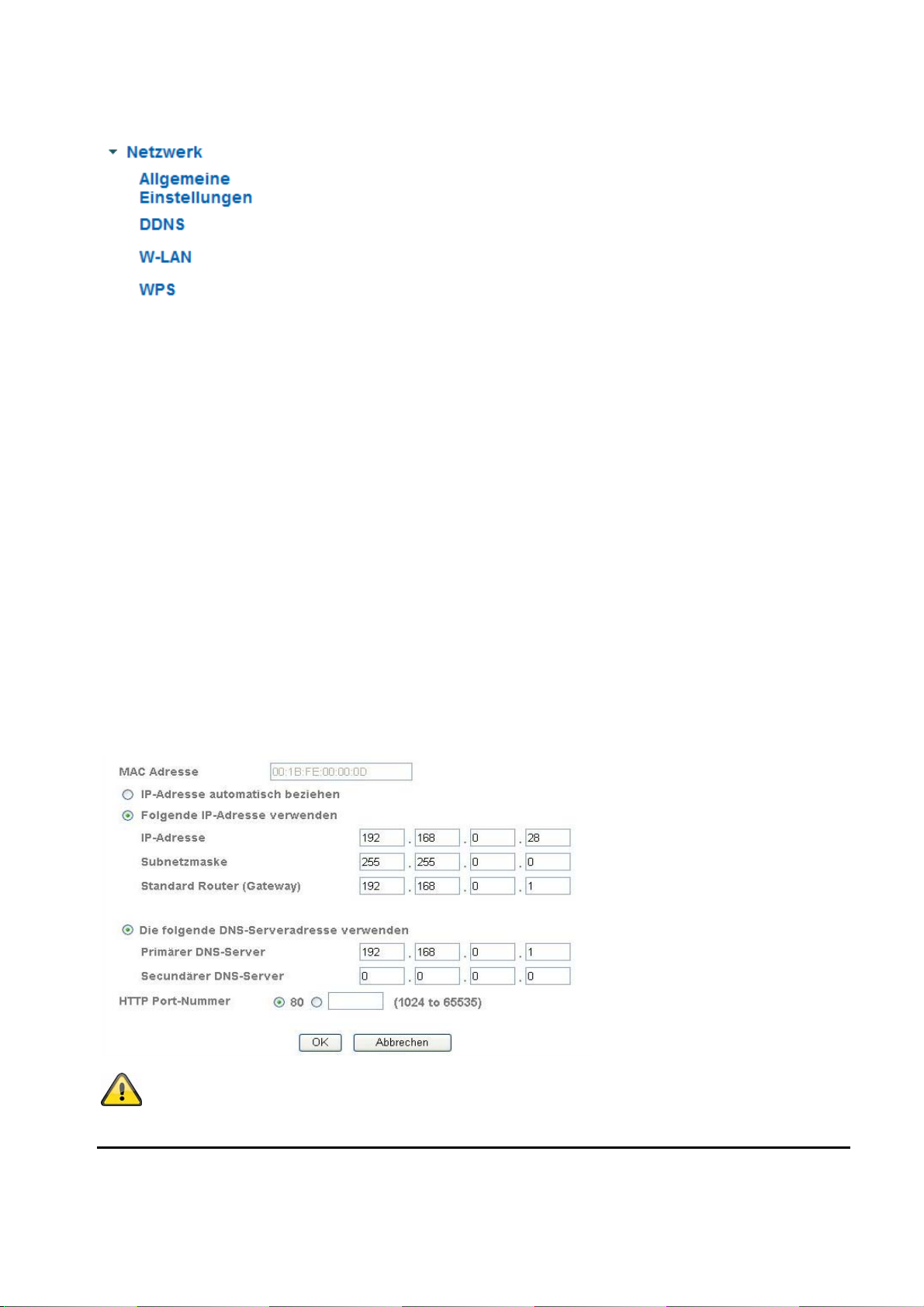
6.4 Network
General settings
MAC address:
Obtain IP address automatically:
Use the following IP address:
IP address:
Subnet mask:
Standard router (gateway):
Use the following DNS server address:
Primary DNS server:
Secondary DNS server:
HTTP port number:
The hardware address of the camera is shown here.
Manual setting of the IP address for the IP camera
Manual setting of the subnet address for the IP camera
The IP address, subnet mask, and address for the default gateway
Manual setting of the IP address, subnet mask, and standard router
Manual setting of the standard router for the IP camera
First server address with which the camera attempts to
Alternative server address with which the camera attempts
The standard port for HTTP transmission is 80. As an alternative,
are obtained automatically from a DHCP server. An activated DHCP
server must be present in the network in this case.
(gateway)
If the DNS server address is not automatically assigned by
a DHCP server, it can be manually assigned here.
convert DNS names into IP addresses.
to convert DNS names into IP addresses.
this port can be assigned a value in the range of 1025–65535. If
several IP cameras are located in the same subnetwork, then each
camera should have its own unique HTTP port.
Accept the settings by pressing “SAVE” or cancel them by pressing “Cancel”. If
the network configuration is changed, then the camera must be restarted (System
\ Initialize \ Restart).
22
Page 23
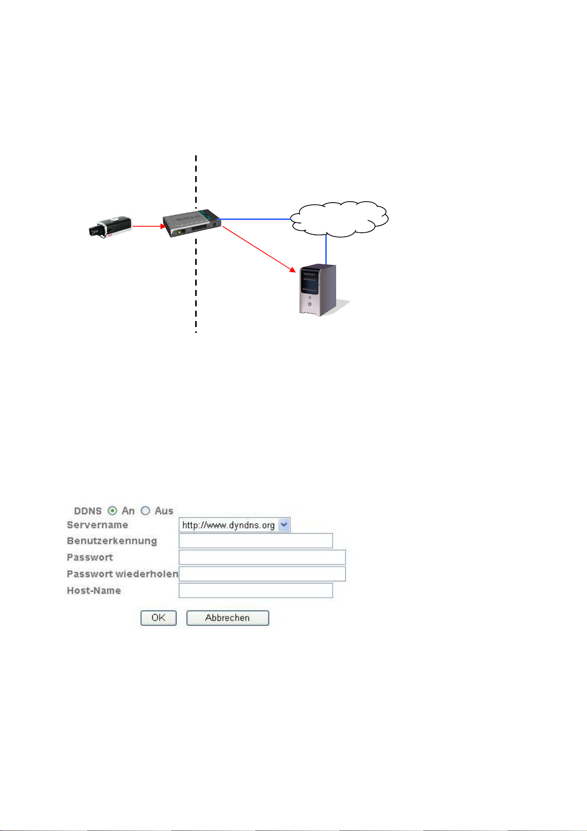
DDNS
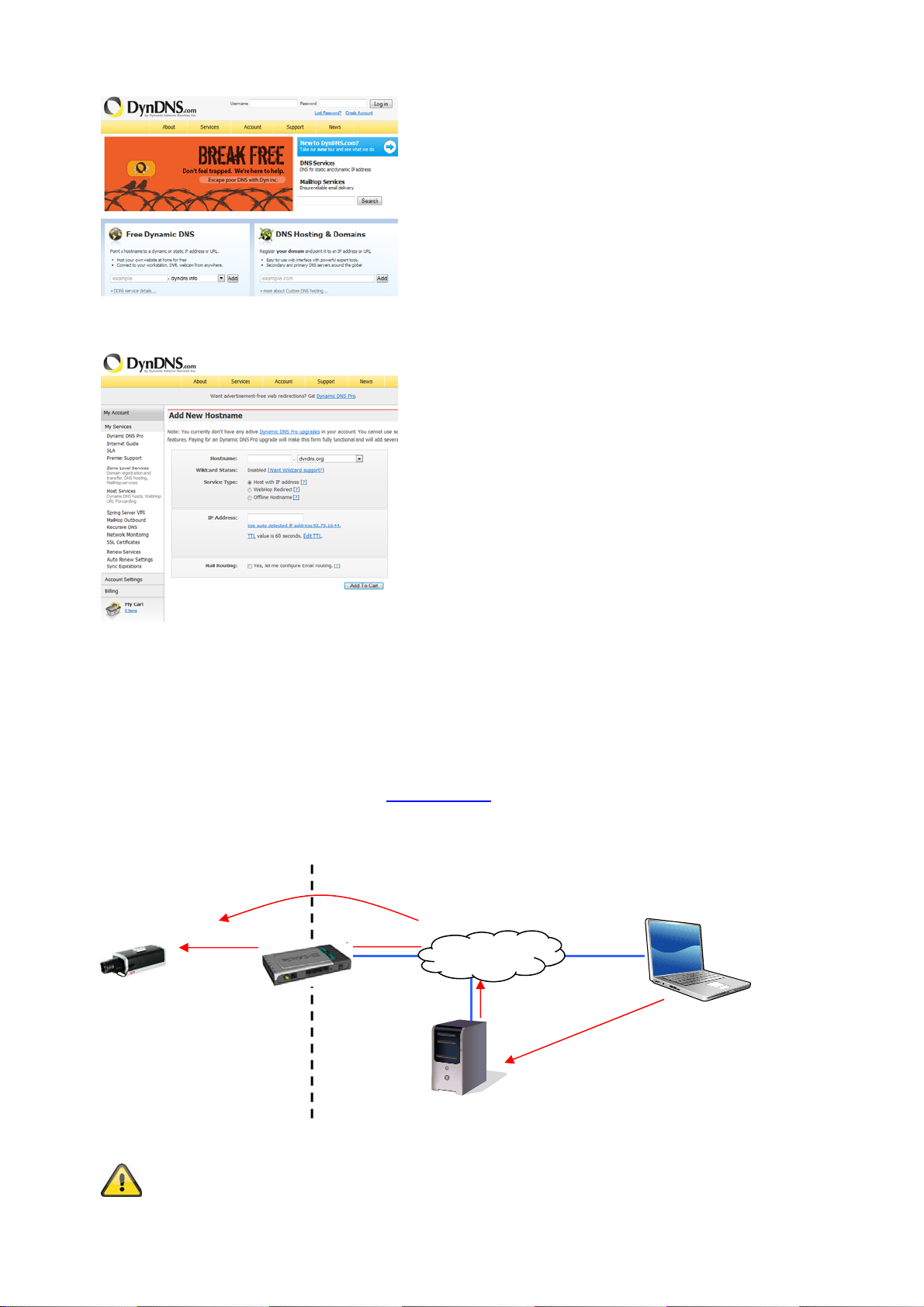
DynDNS or DDNS (dynamic domain name system entry) is a system that can update domain name entries in
real time. The network camera is equipped with an integrated DynDNS client that updates the IP address
independently via a DynDNS provider. If the network camera is located behind a router, we recommend using
the DynDNS function of the router.
The following diagram offers an overview of accessing and updating the IP address using DynDNS.
192.168.0.3
DDNS:
Server name: Select a DDNS service provider. You must have registered access to this DDNS
User ID:
Password: Password of your DDNS account
Repeat password:
Host name: Enter your registered domain name (host service) here (e.g.
Activates or deactivates the DDNS function.
User ID of your DDNS account
LAN WAN
service provider (e.g. www.dyndns.org).
You need to confirm your password here.
myIPcamera.dyndns.org).
195.184.21.78
DynDNS access
data
Internet
195.184.21.78 name.dyndns.org
DynDNS.org
Name Server
Setting up a DDNS account
Set up a new account as follows under DynDNS.org:
23
Page 24
p
y
Store your account information:
Note down your user data and enter this into the configuration of the network camera.
Accessing the network camera over DDNS
If the network camera is located behind a router, then access via DynDNS must be configured in the router.
On the ABUS Security-Center homepage www.abus.com
configuration for common router models.
The following diagram offers an overview of accessing a network camera behind a router via DynDNS.org.
192.168.0.1
, you can find a description of DynDNS router
Internet
195.184.21.78:1026
htt
://name.dyndns.org:1026
LAN WAN
DynDNS.org
Name Server
name.d
ndns.org:1026 195.184.21.78:1026
Port forwarding of all relevant ports (at least RTSP + HTTP) must be set up in the router
in order to use DynDNS access via the router.
24
Page 25

Accept the settings by pressing “SAVE” or cancel them by pressing “Cancel”. If
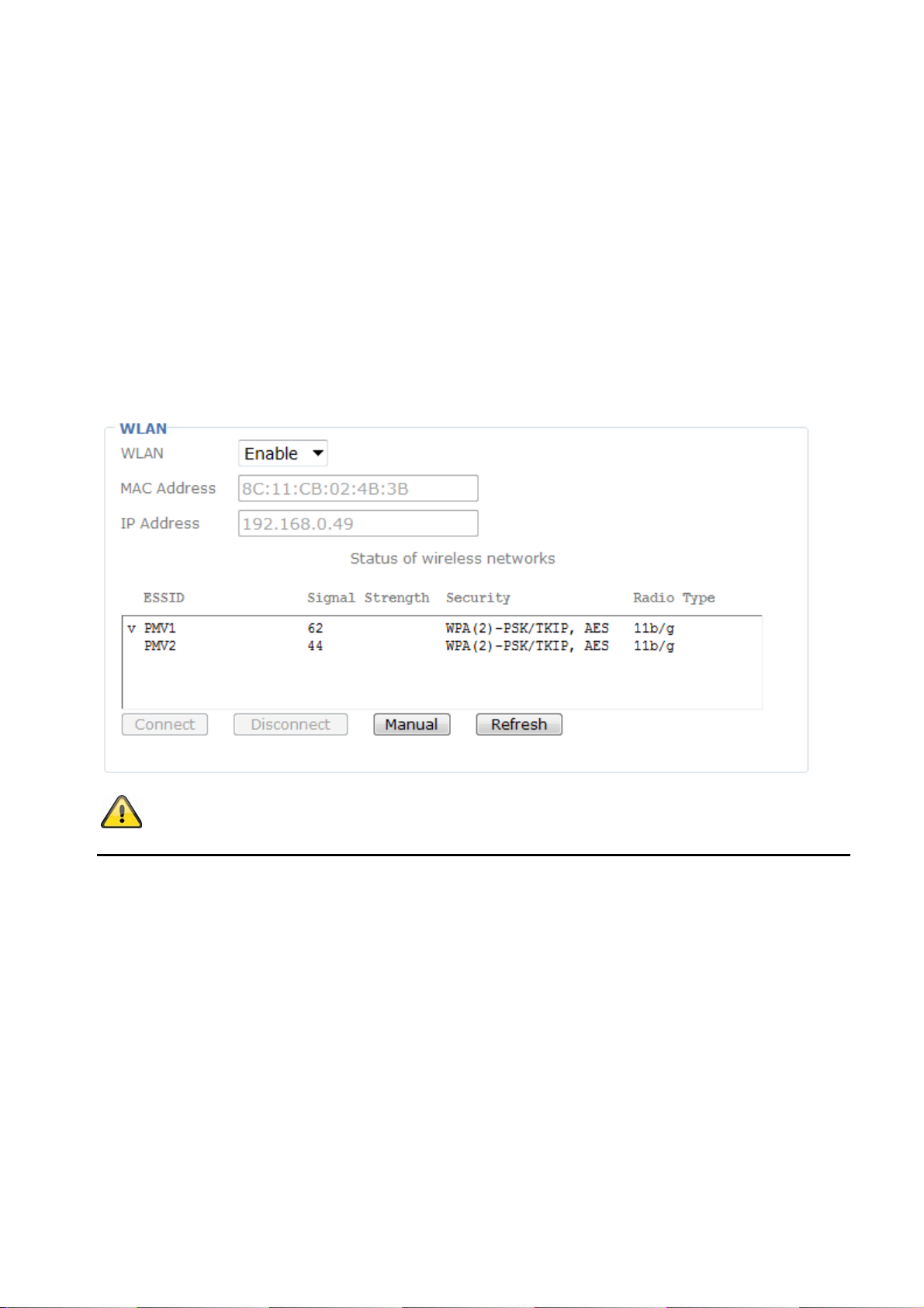
Wireless (TVIP10055B only)
The camera features a WLAN network interface for wireless data transmission in an IP network. The network
camera must be connected via a network cable for the initial configuration of all WLAN parameters.
WLAN:
MAC address: Shows the MAC address of the wireless interface.
IP address: The set IP address is displayed here. The address can be assigned
WLAN status display:
ESSID:
Signal strength:
Security:
Wireless mode:
Connect:
Disconnect:
Manual: Manual configuration of all data required for a wireless connection.
Update: When this button is pressed, the list of available access points is updated.
ESSID:
Manual setting: Manual setting of the ESSID.
Mode:
Select the WLAN connection mode here.
Infrastructure The network camera is connected to the network via an access point.
Ad-Hoc
Authentication:
Open
No encryption selected.
Common key (WEP, Wired Equivalent Privacy) A 64- or 128-bit key is used for encryption
WPA-PSK/WPA2-PSK (Wi-Fi Protected Access – Pre-Shared Keys) With this method, dynamic keys
Encryption:
the network configuration is changed, then the camera must be restarted (System
\ Initialize \ Restart).
Enable or disable the WLAN interface.
automatically (DHCP) or manually (see below).
The camera automatically searches the environment for WLAN access points
(APs).
Shows the name of the wireless network. If a connection to an access point
has been established, this is indicated by the character “v” before the ESSID
name.
Shows the signal quality in percent. To ensure a good connection, this value
should not be below 60%.
Indicates the way in which the network is protected (encryption type).
Shows the WLAN standard that the access point (AP) supports.
When this button is pressed, the software attempts to connect to the selected
access point. Additional data important for the connection must be configured
in another window (it may be necessary to disable the pop-up blocker). The
IP address is automatically determined.
The connection to the selected access point is disconnected.
The ESSID is the name of the access point.
In this mode, the network camera can communicate directly with another
network adapter (network card). What is known as a peer-to-peer
environment is set up.
Here you can set the encryption mode for the wireless transmission.
(HEX or ASCII). For communication with other equipment, these keys must
be the same on both devices.
(10/26 HEX characters or 5/13 ASCII characters according to bit length)
are used. TKIP (Temporal Key Integrity Protocol) or AES (Advanced
Encryption Standard) can be selected as the encryption protocols. What is
known as a passphrase (pre-shared key) must be assigned as the key.
(64 HEX characters or 8 to 63 ASCII characters)
Select the corresponding type of encryption here.
Common key: WEP / disabled
WPA-PSK / WPA2-PSK: TKIP or AES
25
Page 26
Key length: With WEP only. Select the bit length for the key here.
Network key: With WEP only. Up to four keys can be assigned.
Obtain IP address automatically:
Use the following IP address:
Use the following DNS server address:
Primary DNS server:
Secondary DNS server:
First server address with which the camera attempts to
Alternative server address with which the camera attempts
The IP address, subnet mask, and address for the default gateway are
obtained automatically from a DHCP server. An activated DHCP server
must be present in the network in this case.
Manual setting of the IP address, subnet mask, and standard router
(gateway)
If the DNS server address is not automatically assigned by
a DHCP server, it can be manually assigned here.
convert DNS names into IP addresses.
to convert DNS names into IP addresses.
Accept the settings by pressing “SAVE” or cancel them by pressing “Cancel”.
WPS (TVIP10055B only)
WPS (Wi-Fi Protected Setup) is a simple method for establishing a secure wireless network connection
(WPA, WPA2). Consult the manual for your access point (e.g. router with WPS function) regarding the
necessary steps for setting up the WPS function.
WPS:
Enable the WPS function here if required.
MAC address:
IP address: The set IP address is displayed here. The address can be assigned automatically
Configure via:
Shows the MAC address of the wireless interface.
(DHCP) or manually (see below).
PBC:
Push Button Configuration – You set up a secure wireless connection by pressing
the button on the access point or network camera.
PIN:
26
Page 27

A secure wireless connection is set up in the network camera and access point
through the assignment of a PIN. Press the “Generate new PIN” button to assign a
new random PIN. This PIN must then be made known in the access point (WPS
settings). Press “Start”. The network camera and access point are then
automatically connected to each other via a secure connection.
Connect:
Disconnect: The connection is disconnected.
Update:
A connection is established via WPS with the selected procedure (PBC or PIN).
The list of available access points supporting WPS is updated.
6.5 Security
User
This menu item describes the user administration of the network camera. Up to 10 user accounts can be
defined. The user accounts can each have one of three user types.
User list:
Add:
Edit:
Delete:
User types Permissions
Administrator
Operator
Viewer
The default access data for the main administrator is as follows:
User name: “admin”
Password: “12345”
User name:
Password:
Repeat entry:
User type:
Anonymous setting:
Shows all configured users with the corresponding authorization levels.
Add a user account.
Edit an existing user account. Before doing this, you need to select the required user account
from the list.
Delete a user account.
Full access, including live views, configuration
Live view
Live view
Here you assign the user name that needs to be entered for access to the
camera.
Here you assign the user name that needs to be entered for access to the
camera.
Here you assign the password that the corresponding user needs to enter for
access to the camera.
Select an individual user type for the user ID.
Activated Anonymous setting allows any user to see the main page including
video stream. All settings pages are still password protected.
Accept the settings by pressing “SAVE” or cancel them by pressing “Cancel”.
27
Page 28

n
e
a
h
h
h
h
a
e
o
h
o
a
a
r
e
c
v
v
a
c
i
e
i
d
k
e
e
t
d
i
p
y
e
d
o
e
e
e
l
n
s
b
r
o
e
r
a
T
d
e
d
b
r
f
s
d
e
w
s
a
a
s
m
d
h
s
g
c
o
A
p
i
7. Mai
7.1 Fun
Regularly
If safe op
operation.
Safe oper
T
T
T
T
tenance
ction test
check the t
ration is no
ation is no l
e device s
e device n
e device h
e device h
7.2 Clea
ning
Clean the
device with
This p
inside
Ensur
chemi
nd clean
chnical saf
longer poss
nger possib
ows visible
longer wor
s been stor
s been subj
oduct is ma
the product
a clean, dry
that liquid
al cleaning
ng
ty of the pro
ble, cease
le under the
amage.
s correctly.
d in advers
cted to stre
intenance-fr
o check. N
cloth. The c
oes not pe
products, a
duct, e.g. ch
perating th
following ci
conditions
ss during tr
e for you.
ver open it.
oth can be
etrate the d
they could
eck the hou
product an
cumstances
for a long p
nsportation.
here are no
ampened
vice, as thi
amage the
ing for dam
safeguard i
:
riod of time.
component
ith lukewar
will cause
surface of t
age.
t against ac
to service
water if it g
amage. Do
e housing.
idental
r anything
ets dirty.
not use any
8. Disp
osal
De
ices display
ser
ice life, dis
Ple
se contact
ele
tronic wast
ng this sym
ose of the p
our dealer
.
ol may not
roduct acco
r dispose o
e disposed
ding to the
the product
of as dome
pplicable le
at the loca
tic waste.
al requirem
l collection
t the end of
ents.
oint for
ts
28
Page 29

9. Technical data
Item number TVIP10005B TVIP10055B
Image sensor 1/4’’ Progressive Scan CMOS Sensor
Camera type Farbkamera Farbkamera
Resolution 640x480, 320x240, 160x120
Picture elements (total) 640x480
Picture elements (effective) 640x480
Lens f=1,7 mm
Horizontal viewing angle 67°
Digital zoom 10x
Image Compression MJPEG
Frame rate
Electronic-Shutter-Control Auto
White balance Yes
Gain control 0-9 dB
Backlight compensation BLC
Supported Browser Mozilla Firefox, Apple Safari, Google Chrome or Internet Explorer 6.x and higher
Supoorted Software Network connector RJ-45 Ethernet 10/100 Base-T
Network protocols
Wireless - IEEE 802.11b/g/n
Access control IP-address filter, username, password, 3 user levels
Power supply 5 V DC
Current consumption 260 mA
Working temperture 0°C ~ 35°C
IP protection grade IP34
Dimensions (WxHxD) 63 x 77 x 32 mm
Certifications CE, RoHS, WEEE, REACH
TCP/IP, DHCP, PPPoE, ARP, ICMP, DNS, NTP, UPnP, HTTP, TCP, UDP, ABUS
MJPEG: 25 Images/s @ 640x480,
MJPEG: 25 Images/s @ 320x240,
MJPEG: 25 Images/s @ 160x120,
Server
29
Page 30

10. GPL license information
Here we wish to inform you that the network surveillance cameras TVIP10005B and TVIP10055B contain
Open Source Software, which is licensed exclusively under the GNU General Public License (GPL). To
ensure that your use of the programs conforms with GPL, please refer to the GPL license conditions.
License text
The license text for the GNU General Public License can be viewed on the enclosed software CD.
Source code
The source code in use can be obtained from ABUS Security-Center upon request if you send an e-mail to
license@abus-sc.com up to three years after purchase.
Executability of the overall system
The software packets (source code) do not enable you to set up a functional overall system. You also need a
variety of software applications and the hardware developed for the network camera system.
30
Page 31

0
cj
Z
a
ę
c
u
ę
a
a
o
m
p
ś
A
g
P
a
o
ewn
sie
trzn
iow
kam
VG
era
Wersja
Instruk
3/2013
a obsługi
przetłum
czona z j
Instr
kcja
zyka nie
rzyszło
bsłu
ieckiego.
ci!
i
rzechow
ć do wyk
rzystania w
Page 32

Wprowadzenie
Szanowna Klientko, Szanowny Kliencie.
Dziękujemy za zakup naszego produktu.
Produkt ten spełnia wymagania obowiązujących norm europejskich i krajowych. Zgodność została
udokumentowana, odpowiednie deklaracje i dokumenty są dostępne u producenta.
Aby zachować ten stan i zapewnić bezpieczną eksploatację, użytkownik musi przestrzegać niniejszej
instrukcji obsługi!
Przed uruchomieniem produktu przeczytaj całą instrukcję obsługi i przestrzegaj wszystkich zasad
bezpieczeństwa!
Wszystkie zawarte w niej nazwy firm i oznaczenia produktów są zarejestrowanymi znakami
towarowymi odnośnych właścicieli. Wszystkie prawa zastrzeżone.
W razie wątpliwości zwracaj się do instalatora lub sprzedawcy!
Wyłączenie odpowiedzialności cywilnej
Niniejsza instrukcja obsługi została opracowana z najwyższ
braki lub niedokładności, prosimy o ich zgłaszanie na adres podany na odwrocie niniejszego podręcznika.
ABUS Security-Center GmbH nie odpowiada za błędy techniczne i typograficzne oraz zastrzega sobie
prawo do wprowadzania w każdej chwili bez wcześniejszej zapowiedzi zmian w produkcie i w instrukcjach
obsługi.
ABUS Security-Center nie odpowiada za bezpośrednie i pośrednie szkody następcze , powstałe w związku
z wyposażeniem, osiągami i zastosowaniem produktu. Zawartość niniejszego dokumentu nie jest objęta
gwarancją.
32
ą starannością. Jeżeli mimo to zauważysz w niej
Page 33

Objaśnienie symboli
Symbol błyskawicy w trójkącie jest stosowany w celu wskazania na zagrożenie dla
zdrowia, np. wskutek porażenia elektrycznego.
Wykrzyknik w trójkącie oznacza w niniejszej instrukcji obsługi ważne wskazówki, które
muszą być bezwzględnie przestrzegane.
Tym symbolem oznaczane są specjalne rady i wskazówki dotyczące obsługi.
Ważne zasady bezpieczeństwa
Szkody spowodowane nieprzestrzeganiem niniejszej instrukcji obsługi powodują
wygaśnięcie roszczeń gwarancyjnych. Nie odpowiadamy za szkody następcze!
Nie odpowiadamy za szkody materialne lub osobowe, spowodowane nieprawidłową
Szanowna Klientko, Szanowny Kliencie. Celem poniższych informacji dotyczących bezpieczeństwa i
zagrożeń jest nie tylko ochrona Twojego zdrowia, ale także ochrona urządzenia. Dlatego przeczytaj
dokładnie poniższe punkty.
obsługą lub nieprzestrzeganiem zasad bezpieczeństwa. W takich przypadkach wygasają
wszelkie roszczenia gwarancyjne!
Wewnątrz produktu nie ma żadnych części wymagających konserwacji. Otwarcie/rozebranie produktu
pociąga za sobą unieważnienie dopuszczenia (CE) oraz gwarancji/rękojmi.
Upadek nawet z niewielkiej wysokości może spowodować uszkodzenie produktu.
Urządzenie jest przewidziane tylko do użytku we wnętrzach.
Zamontuj produkt tak, aby światło słoneczne nie mogło padać bezpośrednio na czujnik obrazowy
urządzenia. Przestrzegaj wskazówek montażowych zawartych w odpowiednim rozdziale niniejszej
instrukcji obsługi.
Unikaj wymienionych niżej niekorzystnych warunków otoczenia w czasie eksploatacji urządzenia.
Wilgoć lub za wysoka wilgotność powietrza.
Skrajne zimno lub gorąco.
Bezpośrednie nasłonecznienie.
Zapylenie, palne gazy, opary lub rozpuszczalniki.
Silne wibracje.
Silne pola magnetyczne, występujące np. w pobliżu maszyn lub głośników
Kamera nie może być instalowana na niestabilnych powierzchniach.
Ogólne zasady bezpieczeństwa
Nie zostawiaj porozrzucanych materiałów opakowania! Folie/torebki plastikowe, elementy
styropianowe itd. mogą stać się niebezpieczną zabawką w rękach dzieci.
Ze względu na bezpieczeństwo kamera wideo do monitoringu, zawierająca małe części, które mogą
zostać połknięte, nie może być udostępniana dzieciom.
Nie wprowadzaj żadnych przedmiotów przez otwory do wnętrza urządzenia.
ywaj tylko podanych przez producenta urządzeń/akcesoriów. Nie podłączaj niezgodnych
Uż
produktów.
Przestrzegaj zasad bezpieczeństwa i instrukcji obsługi pozostałych podłączonych urządzeń.
Przed uruchomieniem sprawdź, czy urządzenie nie jest uszkodzone. Jeżeli jest, nie wolno go
uruchamiać!
Zachowaj napięcie robocze w granicach podanych w danych technicznych. Wyższe napięcia mogą
zniszczyć urządzenie oraz zagrażać bezpieczeństwu użytkownika (porażenie elektryczne).
33
Page 34

Zasady bezpieczeństwa
1. Zasilanie elektryczne: zasilacz sieciowy 110-240 VAC, 50/60 Hz / 5 VDC, 1,0 A (w zakresie dostawy)
Zasilaj urządzenie tylko ze źródła napięcia sieciowego zgodnego z podanym na tabliczce znamionowej.
W razie wątpliwości co do parametrów lokalnego zasilania elektrycznego zwróć się do właściwego
zakładu energetycznego. Przed przystąpieniem do konserwacji lub instalacji odłącz urządzenie od
zasilania sieciowego.
2. Przeciążenie
Unikaj przeciążania gniazd sieciowych, przedłużaczy i adapterów, ponieważ może to spowodować pożar
lub porażenie elektryczne.
3. Czyszczenie
Czyść urządzenie tylko wilgotną ściereczką bez ostro działających środków czyszczących.
Przed czyszczeniem odłącz urządzenie od sieci.
Ostrzeżenia
Przed pierwszym uruchomieniem należy spełnić wszystkie wymagania okreś
bezpieczeństwa i instrukcji obsługi!
1. Przestrzegaj tych wskazówek. Ich nieprzestrzeganie może doprowadzić do porażenia elektrycznego.
W czasie pracy nigdy nie otwieraj obudowy ani zasilacza sieciowego.
Nie wkładaj do wnętrza urządzenia przedmiotów metalowych lub łatwopalnych.
Aby uniknąć uszkodzeń w wyniku przepięć (np. w czasie burzy), zastosuj zabezpieczenia
przepięciowe.
2. Uszkodzone urządzenia odłącz niezwłocznie od sieci elektrycznej i poinformuj sprzedawcę.
Instalując urządzenie w istniejącej instalacji monitoringu wideo upewnij się, czy wszystkie
urządzenia są odłączone od obwodu sieciowego i obwodu niskiego napięcia.
lone w zasadach
W razie wątpliwości nie wykonuj montażu, instalacji i okablowania samodzielnie, lecz zleć ich
wykonanie specjaliście. Nieprawidłowe i niefachowo wykonywane prace na sieci elektrycznej i
instalacjach wewnętrznych stwarzają niebezpieczeństwo dla użytkownika a także dla innych
osób.
Okabluj instalację tak, aby obwód sieciowy i obwód niskiego napięcia były ułożone osobno i
nie stykały się w żadnym miejscu ani nie mogły zostać połączone w wyniku uszkodzenia.
Rozpakowanie
Rozpakowując urządzenie, należy postępować bardzo delikatnie.
W razie stwierdzenia uszkodzenia oryginalnego opakowania, sprawdź najpierw urządzenie.
W razie stwierdzenia uszkodzeń urządzenia, odeślij je wraz z opakowaniem, informując
jednocześnie przewoźnika.
34
Page 35

Spis treści
1. Użycie zgodne z przeznaczeniem........................................................................................ 36
2. Zakres dostawy ..................................................................................................................... 36
3. Montaż ................................................................................................................................... 37
3.1 Zasilanie napięciowe ............................................................................................................ 37
3.2 Montaż kamery ...................................................................................................................... 37
4. Opis kamery .......................................................................................................................... 37
4.1 Opis złącz .............................................................................................................................. 37
4.2 Wskaźniki stanu .................................................................................................................... 38
4.3 Przywracanie ustawień fabrycznych .................................................................................. 38
4.4 Pierwsze uruchomienie ........................................................................................................ 39
4.5 Pierwszy dostęp do kamery sieciowej ................................................................................ 40
4.6 Dostęp do kamery sieciowej z przeglądarki WWW ............................................................ 41
4.7 Instalacja wtyczki ActiveX ................................................................................................... 41
4.8 Dostosowanie ustawień bezpieczeństwa ........................................................................... 41
4.9 Sprawdzanie hasła ................................................................................................................ 42
5. Funkcje użytkownika ............................................................................................................ 43
5.1 Sterowanie wideo ................................................................................................................. 44
6. Ustawienia kamery (konfiguracja) ....................................................................................... 46
6.1 System ................................................................................................................................... 47
6.2 Wideo ..................................................................................................................................... 50
6.3 Audio ...................................................................................................................................... 50
6.4 Sieć ........................................................................................................................................ 51
6.5 Użytkownicy .......................................................................................................................... 58
7. Konserwacja i czyszczenie .................................................................................................. 59
7.1 Test działania ........................................................................................................................ 59
7.2 Czyszczenie ........................................................................................................................... 59
8. Utylizacja ............................................................................................................................... 59
9. Dane techniczne ................................................................................................................... 60
10. Informacja licencyjna GPL ................................................................................................... 61
35
Page 36

c
i
n
e
e
w
i
;
d
w
e
Ad
e
o
s
ó
w
a
s
e
c
z
e
ż
A
w
w
ł
m
p
n
d
d
j
n
c
o
e
y
e
o
u
o
b
t
r
o
z
w
w
g
1. Uży
Kamera s
zewnętrz
2. Zakr
ie zgodn
eciowa jest
ego.
Użycie
Każde i
rękojmi
przebu
Przed u
obsługi
es dosta
Kam
TVIP10
Kab
CD z
i in
z przezn
yposażon
nne niż opi
nne użycie j
wykluczają
owy i/lub pr
ruchomieni
zawiera wa
y
ra sieciowa
005B / TVIP
apter siecio
l sieciowy 1
programo
trukcją obs
aczenie
w wysokiej
ane może s
st niezgod
wszelką o
eróbek pro
m produktu
ne informac
BUS
10055B
y
metr
aniem
ugi
jakości czuj
owodować
e z przezna
powiedzialn
uktu.
przeczytaj k
je dotycząc
ik obrazow
uszkodzeni
zeniem i p
ość cywilną.
mpletnie i
montażu i
. Służy ona
produktu a
ciąga za so
Dotyczy to
ważnie inst
bsługi.
do wideom
także inne
ą utratę g
akże samo
ukcję obsłu
nitoringu
agrożenia.
arancji lub
olnej
i. Instrukcja
Wspornik
Skr
cona instru
kcja
36
Page 37

3. Montaż
Upewnij się, czy zostały dostarczone wszystkie akcesoria i produkty wymienione na powyższej liście. Do
pracy kamery niezbędny jest kabel Ethernet. Kabel Ethernet musi być zgodny ze specyfikacją kategorii UTP 5
(CAT 5) i nie może być dłuższy niż 100 metrów.
3.1 Zasilanie napięciowe
Przed przystąpieniem do wykonania instalacji upewnij się, czy napięcie sieci jest zgodne z napięciem
znamionowym kamery. Kamera może być zasilana tylko napięciem 5 V DC. Użyj dostarczonego w komplecie
zasilacza wtyczkowego.
3.2 Montaż kamery
Razem z kamerą dostarczany jest uchwyt do montażu. Z tyłu kamery znajduje się podstawka do
zamocowania uchwytu kamery. Uchwyt kamery można zamocować do ściany lub sufitu za pomocą
dostarczonych w komplecie kołków rozporowych i śrub.
4. Opis kamery
4.1 Opis złącz
Strona przednia
1
2
3
1 Obiektyw
2
Mikrofon
3 Dioda informacyjna stanu
4 Złącze sieciowe
5
Złącze do zasilania napięciowego 5 V DC
6 Dioda stanu LED WPS (tylko TVIP10055B)
Strona tylna
4
5
9
7
6
8
a
7 Przycisk WPS (tylko TVIP10055B)
Przycisk Reset
8
9 Podstawka do zamocowania uchwytu
kamery (gwint 1/4‘‘ )
a
Naklejka na produkcie (zawiera m.in.
oznaczenie typu i adres MAC)
37
Page 38

4.2 Wskaźniki stanu
LED Kolor Znaczenie
LED stanu Czerwona światło
ciągłe
Czerwona migająca
1 raz na sekundę
Niebieska światło
ciągłe
WPS LED Migająca 1 raz na
sekundę
Procedura startowa (proces ładowania (boot))
Jeżeli do kamery jest podłączony kabel sieciowy,
kamera próbuje wyznaczyć prawidłowy adres IP
(przez DHCP lub z wykorzystaniem
skonfigurowanego stałego adresu IP).
Jeżeli jest skonfigurowana sieć WLAN, kamera
próbuje nawiązać połączenie z punktem
dostępowym na podstawie danych skonfigurowanej
sieci WLAN.
Brak połączenia sieciowego.
LAN: niepodłączony lub uszkodzony kabel sieciowy
WLAN: wprowadzone dane WLAN nie zostały
zaakceptowane przez punkt dostępowy albo punkt
dostępowy jest poza zasięgiem.
Adres IP został skutecznie przydzielony (uwaga:
adres IP może nie pasować do pożądanej sieci
docelowej; może to się zdarzyć przy ręcznym
przydzieleniu stałego adresu IP).
Zostało uruchomione wyszukiwanie WPS (wciśnij
przycisk WPS na kamerze i przytrzymaj przez
ponad 10 sekund). Kamera spróbuje wymienić
ustawienia bezpieczeństwa dla sieci WLAN z
punktem dostępowym/routerem obsługującym i
mającym aktywny protokół WPS.
4.3 Przywracanie ustawień fabrycznych
Przycisk Reset na tyle kamery ma następujące funkcje.
Restart kamery Naciśnij i puść przycisk Reset. Kamera zostanie
zrestartowana.
Przywracanie ustawień fabrycznych Wciśnij przycisk Reset i przytrzymaj dłużej niż przez 10
sekund.
38
Page 39

4.4 Pierwsze uruchomienie
Kamera sieciowa automatycznie wykrywa, czy konieczne jest bezpośrednie połączenie między PC i kamerą.
Nie jest do tego potrzebny kabel z przeplotem (Cross-Over). Do bezpośredniego podłączenia w celu
pierwszego uruchomienia można użyć dostarczonego w komplecie kabla skrętkowego.
Bezpośrednie podłączenie kamery sieciowej do komputera PC/laptopa
1. Upewnij się, czy do połączenia używasz kabla sieciowego typu Cat5.
2. Połącz kabel ze złączem Ethernet komputera PC/laptopa i kamery sieciowej.
3. Podłącz zasilanie napięciowe kamery sieciowej.
4. Skonfiguruj interfejs sieciowy komputera PC/laptopa na adres IP 192.168.1.1 a Default Gateway
na 192.168.1.2.
5. Przejdź do punktu 4.6, aby zakończyć pierwsze konfigurowanie i nawiązać połączenie z kamerą
sieciową.
Kabel Ethernet Cat5
Podłączenie kamery sieciowej do rutera/przełącznika
1. Upewnij się, czy do połączenia używasz kabla sieciowego Cat5.
2. Połącz komputer PC/laptop z ruterem/przełącznikiem.
3. Połącz kamerę sieciową z ruterem/przełącznikiem.
4. Podłącz zasilanie napięciowe kamery sieciowej.
5. Jeżeli w sieci dostępny jest serwer nazw (DHCP), ustaw interfejs sieciowy komputera PC/laptopa
na „Automatyczne pobieranie adresu IP”.
6. Jeżeli w sieci nie ma serwera nazw (DHCP), skonfiguruj interfejs sieciowy komputera PC/laptopa
na adres 192.168.1.1 a Default Gateway na 192.168.1.2
7. Przejdź do punktu 4.6, aby zakończyć pierwsze konfigurowanie i nawiązać połączenie z kamerą
sieciową.
Internet
39
Page 40

4.5 Pierwszy dostęp do kamery sieciowej
Do pierwszego dostępu do kamery sieciowej należy użyć Instalatora IP ABUS.
Po uruchomieniu Asystent wyszukuje wszystkie podłączone kamery sieciowe ABUS i serwery wideo w sieci.
Program ten jest zapisany na dołączonej płycie CD-ROM. Zainstaluj program na komputerze PC i wykonaj
go.
Jeżeli w twojej sieci jest serwer DHCP, adres IP zostanie automatycznie przydzielony dla komputera
PC/laptopa a także dla kamery sieciowej.
Jeżeli serwer DHCP jest niedostępny, kamera sieciowa samodzielnie ustala wolny adres IP z zakresu
192.168.1.2 – 192.168.1.254. Twój system PC musi znajdować się w tym samym segmencie IP, aby możliwa
była komunikacja z kamerą sieciową.
Standardowo kamera sieciowa jest ustawiona na „DHCP”. Jeżeli w Twojej sieci nie używasz
serwera DHCP, radzimy po pierwszym dostępie do kamery sieciowej ręczne ustawienie adresu
IP na stałą wartość.
40
Page 41

t
w
w
e
e
ł
z
e
a
a
t
m
k
n
p
w
e
c
o
A
a
e
m
t
o
i
e
a
m
o
r
r
v
ń
a
d
z
k
z
c
z
e
w
t
z
t
w
z
c
e
a
a
a
w
r
a
m
c
W
z
a
p
w
ć
M
a
a
k
W
w
y
n
s
c
o
J
r
e
o
d
m
m
y
s
T
C
m
ż
y
4.6 Dos
Przy pier
zainstalo
bezpiecz
bezpiecz
wtyczka s
kliknąć pr
bezpiecz
administr
4.7 Inst
ęp do ka
szym dostę
anie wtycz
ństwa inter
ństwa, kom
uży do wyś
ycisk „Insta
ństwa w int
tora sieci.
lacja wty
ery sieci
pie do kam
i ActiveX dl
etowego ko
uter może
ietlania ob
luj”. Jeżeli p
rnecie i obn
zki Acti
owej z pr
ry sieciowej
kamery sie
putera uży
dmówić ws
azów wideo
zeglądarka
iż poziom b
eX
eglądark
w systemie
ciowej. To,
tkownika. J
elkiej instal
w przegląd
uniemożliwi
zpieczeńst
i WWW
indows pr
zy takie pyt
żeli ustawio
cji i każdej
rce Aby kon
kontynuo
a lub zwró
eglądarka
nie się poja
y jest najw
róby wyko
tynuować in
anie instala
się do admi
WW pyta
wi, zależy o
ższy pozio
ania progra
stalację, uż
ji, otwórz u
nistratora I
ustawień
u. Ta
tkownik mo
tawienia
lub
e
4.8 Dos
Jeżeli d
pple S
osowani
dostępu do
fari, zamias
ustawie
kamery uży
wtyczki Ac
bezpiec
wana jest p
iveX kamer
eństwa
zeglądarka
udostępni
ozilla Firef
strumień M
x, Google
PEG.
hrome lub
Uwaga:
odbiór s
internet
uaktywn
oże się zd
rumienia wi
we/Bezpiec
one kontrol
rzyć, że us
eo. Trzeba
eństwo” po
i ActiveX i p
awienia bez
ówczas z
iom bezpie
obieranie pli
41
pieczeństw
ienić w pun
zeństwa na
ków.
w kompute
cie „Dodatk
niższy. Prz
ze PC unie
i/Opcje
de wszystki
ożliwią
m muszą b
ć
Page 42

4.9 Sprawdzanie hasła
Fabrycznie kamera sieciowa ma ustalone hasło administratora. Ze względu na bezpieczeństwo administrator
powinien jednak jak najszybciej zdefiniować nowe hasło. Po zapisaniu hasła administratora kamera sieciowa
pyta przed każdym dostępem o nazwę użytkownika i hasło.
Fabryczne ustawienia konta administratora są następujące: nazwa użytkownika „admin” i hasło „12345”. Przy
każdym dostępie do kamery sieciowej w przeglądarce wyświetlane jest okno autoryzacji a w tym oknie
pytanie o nazwę użytkownika i hasło. Jeżeli indywidualne ustawienia konta administratora nie są dostępne,
można przywrócić ustawienia fabryczne kamery sieciowej i zalogować się z danymi „admin” / „12345”.
Aby wprowadzić nazwę użytkownika i hasło, wykonaj następujące czynności.
Otwórz Internet Explorer i wprowadź adres IP kamery (np. „http://192.168.1.14”).
Alternatywnie wyszukaj kamerę za pomocą dostarczonego w komplecie oprogramowania instalacyjnego
ABUS IP.
Otworzy się okno, w którym należy podać nazwę użytkownika i hasło.
Standardowa nazwa użytkownika:
admin
Standardowe hasło:
12345
-> Jesteś teraz połączony z kamerą sieciową i wyświetlany jest strumień wideo.
42
Page 43

5. Funkcje użytkownika
Otwórz stronę startową kamery sieciowej. Interfejs jest podzielony na następujące główne części.
Ustawienia kamery
Wyświetlacz
obrazu na żywo
Sterowanie wideo
Wyświetlacz obrazu na żywo
Podwójnym kliknięciem możesz przejść do widoku pełnoekranowego (tylko w przeglądarce Internet Explorer)
Ustawienia kamery
Ustawienia (konfiguracja)
Wykonaj konfigurację (ustawienia administratora)
43
Page 44

5.1 Sterowanie wideo
Te funkcje są dostępna tylko w przeglądarce Internet Explorer!
Przeglądarka WWW otwiera nowe okno, w którym wyświetlane jest zdjęcie migawkowe. Aby je zapisać, kliknij
albo obraz zdjęcia migawkowego lewym przyciskiem myszy i użyj symbolu dyskietki albo użyj funkcji Zapisz
po kliknięciu prawym przyciskiem myszy.
Uaktywnij widok z pełnym obrazem. Obraz na żywo z kamery sieciowej zostanie wyświetlony na całym
ekranie.
Live Stream można zatrzymać lub zakończyć. W obu przypadkach symbolem Play można kontynuować
wyświetlanie obrazu na żywo (Live Stream).
Można uruchomić lub zatrzymać zapis na lokalnym twardym dysku. Kliknięcie przycisku graficznego wywołuje
dialog zapisu systemu.
Zdjęcie
migawkowe
Pełny obraz
Zapis lokalny
Start/Stop wyświetlania obrazu na
żywo
Wybierz folder docelowy na twardym dysku. W folderze docelowym automatycznie zostanie utworzony
katalog i plik zapisu z następującym identyfikatorem:
RRRRMMDD
RRRRMMDDGGmmss.avi
R = rok
M = miesiąc
D = dzień
S = godzina
m = minuta
s = sekunda
44
Page 45

Przykład
C:\Zapis\20091215\20091215143010.avi
Zapisane dane można odtwarzać odtwarzaczem wideo obsługującym format MP4 (np. VLC
Kliknij symbol lupy, aby uaktywnić funkcję zoomu cyfrowego. Suwakiem można zmieniać współczynnik
powiększenia/zmniejszenia (zoom).
Zmień współczynnik powiększenia/zmniejszenia, przesuwając belkę z lewej strony (mniejszy współczynnik) w
prawo (większy współczynnik).
Mediaplayer). Po instalacji kodeków wideo Instalatorem IP można alternatywnie oglądać
nagrania wideo w przeglądarce Windows Mediaplayer.
Zoom cyfrowy
Ustawianie współczynnika
powiększenia/zmniejszeni
a
45
Page 46

6. Ustawienia kamery (konfiguracja)
Tylko administrator ma dostęp do konfiguracji systemu. Każda kategoria podana w lewej kolumnie zostanie
objaśniona na następnych stronach. Kliknięcie pożądanego punktu menu może spowodować jego
rozszerzenie w drzewo menu, zależnie od tego, ile punktów submenu zawiera ten punkt menu. Następnie
kliknij w odpowiedni punkt submenu.
Przycisk graficzny „Strona startowa” przenosi do strony głównej kamery.
46
Page 47

6.1 System
Informacje
Nazwa produktu
Aktualna wersja Podaje wersję aktualnie zainstalowanego oprogramowania firmware.
Parametry obrazu
Jasność Aktualnie ustawiony poziom jasności
Kontrast
Nasycenie Aktualnie ustawiony poziom nasycenia
Ostrość Aktualnie ustawiony poziom ostrości
Kompensacja bieli:
Wideo
Rozdzielczość Aktualna wartość rozdzielczości
Maksymalna częstotliwość odświeżania obrazu: Aktualna częstotliwość odświeżania obrazu
Częstotliwość światła
Sieć
Stan sieci LAN: Aktualnie wykorzystywany adres IP i port HTTP
Stan sieci W-LAN Informacje o wykorzystaniu WLAN
Aktualnie ustawiony poziom kontrastu
Nazwa produktu informuje o jego funkcjach (np. VGA, WLAN).
Wybrana opcja dla kompensacji bieli
47
Page 48

LED
Tu możesz włączyć/wyłączyć diodę stanu LED na przedzie kamery.
LED
Nazwa hosta
Nazwa kamery
Data/czas
Nazwa, pod którą kamera jest rozpoznawana w sieci. Standardowo jest tu wpisany numer
artykułu.
Aktualna data/czas
Zegar PC Podaje datę/czas komputera PC, z którego wykonywany jest dostęp do kamery.
Format daty/czasu
Metoda synchronizacji
Zachowaj aktualne ustawienia
Synchronizuj z PC
Ustawienie ręczne Ustaw ręcznie datę i czas.
Synchronizuj z serwerem NTP Automatyczna aktualizacja daty i czasu z serwera czasu (Network
Adres serwera NTP
Strefa czasowa
Czas letni Podaj datę zmiany z czasu letniego na zimowy.
Podaje zapisane aktualnie w kamerze ustawienie daty/czasu.
Wybierz format (RRRR-rok, MM-miesiąc, DD-dzień, hh-godzina, mm-minuta, ss-
sekunda)
Bez zmiany ustawień
Data i czas komputera PC będą pobierane przez kamerę.
Time Protocol)
Wprowadź nazwę domeny serwera czasu (np. de.pool.ntp.org)
Wybierz strefę czasową, w której znajduje się kamera.
Potwierdź wykonane ustawienia, naciskając „Zapisz” lub odrzuć je, naciskając
„Przerwij”.
48
Page 49

Inicjalizacja
Restart
Ustawienia standardowe
Kopia bezpieczeństwa
Ładuj ustawienia
Uaktualnij oprogramowanie firmware
Język
Załaduj pakiet językowy
Naciśnięcie tego przycisku graficznego powoduje restart kamery.
Naciśnięcie tego przycisku graficznego ładuje ustawienia fabryczne kamery.
Wymagane jest potwierdzenie wyboru.
Można tu zapisać plik kopii bezpieczeństwa wszystkich ustawień kamery.
Tu można załadować ustawienia zapisane w pliku kopii bezpieczeństwa.
Wybierz w tym celu plik przyciskiem graficznym „Przeszukaj” i wciśnij przycisk
graficzny „Ładuj ustawienia”.
Można tu załadować nowsze oprogramowanie firmware kamery.
Informację o uaktualnionych plikach oprogramowania firmware można znaleźć w
dziale produktów na „http://www.abus.com”.
Można tu ustawić inny język przez załadowanie pliku językowego. Domyślnym
językiem przy wysyłce kamery jest jeden z n/w języków:
TVIP10005B -> angielski
TVIP10055B -> angielski
Pliki językowe są zapisane na dostarczonej w komplecie płycie CD z
oprogramowaniem albo w dziale produktów na stronie „http://www.abus.com”.
49
Page 50

6.2 Wideo
Ustawienia strumienia (MJPEG)
Rozdzielczość
Częstotliwość odświeżania obrazu
Częstotliwość światła
Wybierz jedną z poniższych rozdzielczości (w pikselach):
Za pomocą tej wartości można dostosować kamerę do częstotliwości sieci
Potwierdź wykonane ustawienia, naciskając „Zapisz” lub odrzuć je, naciskając
„Przerwij”.
640x480, 320x240, 160x120
elektrycznej. W Polsce wartość ta wynosi standardowo 50 Hz.
6.3 Audio
Określa częstotliwość odświeżania obrazu w obrazach na sekundę.
Mikrofon
Można tu uaktywnić lub wyłączyć mikrofon wewnętrzny.
Audio, funkcja może być używana tylko w połączeniu z Internet
Explorer.
50
Page 51

6.4 Sieć
Ustawienia ogólne
Adres MAC [informacja]:
Automatyczne pobieranie adresu IP Adres IP, maska podsieci i adres dla domyślnego serwera
Użyj następującego adresu IP
Adres IP
Maska podsieci
Domyślny ruter (Gateway) Ręczne ustawienie domyślnego rutera kamery IP
Użyj następującego adresu serwera DNS
Preferowany serwer DNS:
Wtórny serwer DNS
Port HTTP
Ręczne ustawienie adresu IP kamery IP
Ręczne ustawienie maski podsieci kamery IP
Domyślny port dla transmisji HTTP to 80. Alternatywnie port ten
Tu wyświetlany jest adres sprzętowy kamery.
(Gateway) są automatycznie pobierane z serwera DHCP. W tym
celu w sieci musi znajdować się aktywny serwer DHCP.
Ręczne ustawienie adresu IP; maski podsieci i domyślnego rutera
(Gateway)
Jeżeli adres serwera DNS nie jest automatycznie
przydzielany przez serwer DHCP, można go przydzielić
ręcznie.
Pierwszy adres serwera, na którym kamera próbuje
przetworzyć nazwy DNS na adresy IP.
Alternatywny adres serwera, na którym kamera próbuje
przetworzyć nazwy DNS na adresy IP.
może mieć wartość w zakresie 1025~65535. Jeżeli w tej samej
podsieci znajduje się wiele kamer, każda kamera powinna otrzymać
własny, unikalny port HTTP.
51
Page 52

Potwierdź wykonane ustawienia, naciskając „Zapisz” lub odrzuć je, naciskając
DDNS
DynDNS lub DDNS (Dynamiczny System Zapisu Nazw Domen) to system, który potrafi uaktualniać zapisy
nazw domen w czasie rzeczywistym. Kamera sieciowa jest wyposażona w zintegrowanego klienta DynDNSClient, który może samodzielnie przeprowadzić uaktualnienie adresu IP z serwera DynDNS. Jeżeli kamera
sieciowa jest usytuowana za ruterem, radzimy wykorzystać funkcję DynDNS rutera.
Rysunek przedstawia poglądowo dostęp/aktualizację adresu IP w usłudze DynDNS.
192.168.0.3
DDNS
Uaktywnia lub wyłącza funkcję DDNS.
Nazwa serwera Wybierz dostawcę usługi DDNS. Musisz dysponować zarejestrowanym
Identyfikator użytkownika
Hasło Hasło twojego konta DDNS
Powtórz hasło
„Przerwij”.
195.184.21.78
Internet
Dane dostępowe
DynDNS
LAN WAN
dostępem do tego dostawcy usługi DDNS (np. www.dyndns.org).
DynDNS.org
Name Server
Identyfikator użytkownika twojego konta DDNS
Konieczne jest potwierdzenie hasła.
195.184.21.78 name.dyndns.org
52
Page 53

Nazwa hosta
Konfigurowanie konta DDNS
Konfigurowanie nowego konta w DynDNS.org
Wprowadź zarejestrowaną nazwę domeny (host-service)
(np. mojaKameraIP.dyndns.org).
Zapis informacji o koncie
Zanotuj swoje dane użytkownika i przenieś je do konfiguracji kamery sieciowej.
Dostęp do kamery sieciowej przez DDNS
Jeżeli kamera sieciowa znajduje się za ruterem, należy skonfigurować dostęp przez DynDNS w ruterze Na
stronie domowej ABUS Security-Center www.abus.com można znaleźć opis konfiguracji rutera DynDNS dla
popularnych modeli ruterów.
53
Page 54

p
y
Poniższy rysunek przedstawia poglądowo dostęp do kamery sieciowej znajdującej się za ruterem przez
DynDNS.org.
192.168.0.1
Internet
195.184.21.78:1026
htt
://name.dyndns.org:1026
Dostęp DynDNS przez ruter wymaga skonfigurowania w ruterze przekazywania
W-LAN (tylko TVIP10055B)
Kamera jest wyposażona w interfejs sieciowy W-LAN, co umożliwia bezprzewodowe przesyłanie danych w
sieci IP. W celu pierwszego skonfigurowania wszystkich parametrów W-LAN kamera sieciowa musi być
najpierw połączona kablem sieciowym.
W-LAN
Adres MAC
Adres IP
Wskaźnik stanu W-LAN
ESSID
Siła sygnału
Bezpieczeństwo
Tryb radiowy Wyświetlanie standardu W-LAN obsługującego punkt dostępowy
Łączenie
Odłączanie
Ręcznie
Aktualizacja
wszystkich ważnych portów (co najmniej RTSP + HTTP).
Potwierdź wykonane ustawienia, naciskając „Zapisz” lub odrzuć je, naciskając
„Przerwij”.
Włącz lub wyłącz interfejs W-LAN.
Przedstawia adres MAC bezprzewodowego interfejsu.
Tu wyświetlany jest ustawiony adres IP. Adres może być przydzielany
Pokazuje nazwę sieci bezprzewodowej. Jeśli utworzono połączenie z
Wskaźnik jakości sygnału w procentach. Aby połączenie było dobre, wartość
Po włączeniu przycisku urządzenie próbuje utworzyć połączenie z wybranym
Połączenie z wybranym punktem dostępowym zostaje zerwane.
Ręczna konfiguracja wszystkich danych potrzebnych do połączenia
Po naciśnięciu przycisku lista dostępnych punktów dostępowych jest
LAN WAN
automatycznie (DHCP) lub ręcznie (patrz niżej).
DynDNS.org
Name Server
name.d
ndns.org:1026 195.184.21.78:1026
Kamera automatycznie szuka punktów dostępowych W-LAN (AP, Access
Point) w otoczeniu sieciowym.
punktem dostępowym, przed nazwą ESSID wyświetlany jest znak „v”.
ta nie powinna być mniejsza niż 60%.
Określa sposób zabezpieczenia tej sieci (typ szyfrowania).
(Access Point, AP).
punktem dostępowym. Dalsze dane istotne dla połączenia należy
skonfigurować w innym oknie (ewentualnie wyłączyć blokowanie
wyskakujących okienek!). Adres IP jest ustalany automatycznie.
bezprzewodowego. Jeżeli pożądane jest ręczne przydzielanie adresu IP w
sieci WLAN, należy w tym miejscu wprowadzić wszystkie dane ręcznie.
aktualizowana.
54
Page 55

ESSID to nazwa punktu dostępowego.
ESSID
Ustawienie ręczne
Tryb:
Wybierz w tym miejscu tryb połączenia W-LAN.
Infrastruktura
Ad-Hoc W tym trybie pracy możliwa jest bezpośrednia komunikacja kamery sieciowej
Autoryzacja
Otwarta
Wspólny klucz (WEP, Wired Equivalent Privacy) Do szyfrowania używany jest klucz 64- lub
WPA-PSK / WPA2-PSK
Szyfrowanie
Długość klucza
Klucz sieciowy Tylko dla WEP. Można przydzielić maks. 4 klucze.
Automatyczne pobieranie adresu IP
Użyj następującego adresu IP
Użyj następującego adresu serwera DNS
Pierwotny serwer DNS
Wtórny serwer DNS
Tu można ustawić tryb szyfrowania dla transmisji bezprzewodowej.
Nie wybrano żadnej metody szyfrowania.
Ręczne ustawienie ESSID.
Kamera sieciowa jest łączona z siecią przez punkt dostępowy.
z innym adapterem sieciowym (kartą sieciową). Tworzone jest tzw.
środowisko Peer-to-Peer.
128-bitowy (HEX lub ASCII). Komunikacja z innymi urządzeniami wymaga
zgodności kluczy obu urządzeń.
(10/26 znaków HEX lub 5/13 znaków ASCII, stosownie do liczby bitów)
(Wi-fi Protected Access – Pre-Shared-Keys) W tej metodzie stosowane są
klucze dynamiczne. Jako protokoły szyfrowania można wybrać TKIP
(Temporal Key Integrity Protokoll) lub AES (Advanced Encryption Standard).
Jako klucz musi zostać przydzielona tzw. passphrase (Pre-shared Key).
(64 znaków HEX lub 8 maks. 63 znaki ASCII)
Wybierz odpowiedni tryb szyfrowania.
Wspólny klucz: WEP / wyłączony
WPA-PSK / WPA2-PSK: TKIP lub AES
Tylko dla WEP. Wybierz liczbę bitów klucza.
Adres IP, maska podsieci i adres dla domyślnego serwera (Gateway)
są automatycznie pobierane z serwera DHCP. W tym celu w sieci
musi znajdować się aktywny serwer DHCP.
Ręczne ustawienie adresu IP; maski podsieci i domyślnego rutera
(Gateway)
Jeżeli adres serwera DNS nie jest automatycznie
przydzielany przez serwer DHCP, można go przydzielić
ręcznie.
Pierwszy adres serwera, na którym kamera próbuje
przetworzyć nazwy DNS na adresy IP.
Alternatywny adres serwera, na którym kamera próbuje
przetworzyć nazwy DNS na adresy IP.
55
Page 56

Potwierdź wykonane ustawienia, naciskając „Zapisz” lub odrzuć je, naciskając
„Przerwij”.
56
Page 57

WPS (tylko TVIP10055B)
WPS (Wi-Fi Protected Setup) to prosta metoda utworzenia bezpiecznego bezprzewodowego połączenia
sieciowego (WPA, WPA2). Sprawdź w podręczniku punktu dostępowego (np. Fritz-Box z funkcją WPS), jakie
czynności są niezbędne do skonfigurowania funkcji WPS.
WPS
W razie potrzeby uaktywnij funkcję WPS.
Adres MAC Przedstawia adres MAC bezprzewodowego interfejsu.
Adres IP
Metoda konfiguracji
Łączenie
Odłączanie Przerywanie połączenia
Aktualizacja
Tu wyświetlany jest ustawiony adres IP. Adres może być przydzielany
automatycznie (DHCP) lub ręcznie (patrz niżej).
PBC
Push Button Configuration; konfiguracja bezpiecznego połączenia
bezprzewodowego naciśnięciem przycisku na punkcie dostępowym lub na kamerze
sieciowej.
PIN:
Konfiguracja bezpiecznego połączenia sieciowego przez przydzielenie kodu PIN w
kamerze sieciowej i punkcie dostępowym. Naciśnij przycisk graficzny „Utwórz PIN”,
aby przydzielić losowo nowy kod PIN. Ten kod PIN musi być następnie przekazany
do punktu dostępowego (Ustawienia WPS). Naciśnij przycisk graficzny „Uruchom”.
Kamera sieciowa i punkt dostępowy zostaną automatycznie bezpiecznie połączone.
Tworzenie połączenia poprzez WPS z wybraną procedurą PBC lub PIN.
Aktualizacja listy punktów dostępowych obsługujących WPS.
57
Page 58

6.5 Użytkownicy
Użytkownicy
W tym punkcie menu opisane jest zarządzanie użytkownikami kamery sieciowej. Można utworzyć
maksymalnie 10 kont użytkowników. Do kont użytkowników może być przypisany jeden z 3 typów
użytkownika.
Lista użytkowników:
Dodaj
Dodawanie konta użytkownika.
Edytuj
Edycja istniejącego konta użytkownika. Wcześniej należy zaznaczyć odpowiednie konto
Kasuj
Skasować konto użytkownika.
Typ użytkownika Uprawnienia
Administrator
Operator
Obserwator
Fabrycznie ustawione są następujące dane dostępowe głównego administratora.
Nazwa użytkownika „admin”
Hasło „12345”
Nazwa użytkownika
Hasło
Przydziel w tym miejscu nazwę użytkownika, która musi być wprowadzona w
Powtórz hasło
Typ użytkownika
Anonimowy obserwator
Potwierdź wykonane ustawienia, naciskając „Zapisz” lub odrzuć je, naciskając
„Przerwij”.
Wyświetlanie wszystkich skonfigurowanych użytkowników z odpowiednimi poziomami
uprawnień.
użytkownika na liście.
Pełny dostęp, w tym do widoku Live, konfiguracja
Widok Live
Widok Live
Przydziel w tym miejscu nazwę użytkownika, która musi być wprowadzona w
celu uzyskania dostępu do kamery.
celu uzyskania dostępu do kamery.
Przydziel w tym miejscu hasło, które musi być wprowadzona w celu uzyskania
dostępu do kamery.
Wybierz indywidualny typ użytkownika dla identyfikatora użytkownika.
Jeżeli aktywne jest ustawienie anonimowe, wówczas na dostęp do strony
głównej kamery z obrazem wideo nie wymaga hasła. Strony z ustawieniami są
nadal chronione hasłem.
58
Page 59

s
t
a
p
c
z
r
r
o
o
s
o
i
a
b
p
e
z
a
e
o
b
k
i
o
a
n
d
k
c
a
r
k
e
s
n
s
u
z
d
t
g
e
n
N
c
c
s
z
e
y
e
y
n
z
z
h
w
b
u
o
w
e
e
c
s
y
d
u
n
h
c
z
ń
y
e
z
u
e
n
z
a
o
o
o
a
i
ż
w
m
m
y
z
c
i
7. Kon
7.1 Tes
Sprawdz
Jeżeli są
eksploata
Należy pr
u
u
p
p
erwacja
działani
j regularnie
owody do
ji i zabezpi
yjąć, że be
ządzenie m
ządzenie ni
dłuższym
ciężkich o
7.2 Czy
zczenie
Czyść pr
wodą.
dukt czystą,
Produ
przew
nigdy
Uważ
jego z
uszko
czyszcz
ezpieczeń
rzypuszcze
czyć przed
pieczna ek
widoczne
działa ora
kresie skła
ciążeniach
t nie wyma
dzianych do
twierać.
suchą ścier
j, aby do w
iszczenie.
zić powierz
nie
two technic
ia, że bezpi
rzypadkow
ploatacja ni
szkodzenia
owania w ni
ransportow
a od użytko
kontrolowa
czką. W ra
ętrza urząd
ie używaj c
hnię obudo
ne produkt
eczna ekspl
m uruchom
jest możli
,
ekorzystnyc
ch.
wnika żadn
ia lub kons
ie większy
enia nie do
hemicznych
wy.
, np. czy ob
atacja jest
ieniem.
a, jeżeli:
warunkac
j konserwa
rwacji prze
h zabrudze
tała się żad
środków cz
dowa nie j
iemożliwa,
lub
ji. We wnętr
użytkownik
ściereczkę
na ciecz, po
szczących,
st uszkodz
należy wyc
zu nie ma ż
a, dlatego n
można zwil
nieważ spo
ponieważ m
na.
fać produkt
dnych częś
e należy go
yć letnią
odowałoby
ogą one
i
to
8. Utyli
zacja
oznaczony
Ta
wy
ofaniu z ek
ust
wowymi.
Zw
óć się do sp
ele
trycznego.
h urządzeń
ploatacji pro
rzedawcy lu
nie wolno w
dukt należy
oddaj pro
rzucać raz
utylizować
ukty w kom
m z odpada
godnie z ob
nalnym pun
mi domowy
wiązujący
kcie zbiorcz
i. Po
i przepisam
m złomu
59
Page 60

9. Dane techniczne
Numer typu TVIP10005B TVIP10055B
Czujnik obrazowy Czujnik CMOS 1/4" Progressive Scan
typ kamery Kamera kolorowa Kamera kolorowa
Rozdzielczość 640x480, 320x240, 160x120
Elementy obrazowe (ogółem) 640x480
Elementy obrazowe (efektywne) 640x480
Obiektyw 1,7 mm
Kąt widzenia w poziomie 67°
Zoom cyfrowy 10x
Kompresja obrazu MJPEG
Częstotliwość odświeżania obrazu
Regulacja migawki elektronicznej Automatyczna
Kompensacja bieli Tak
Regulacja wzmocnienia 0-9 dB
Kompensacja oświetlenia konturowego BLC
Obsługiwane przeglądarki Mozilla Firefox, Apple Safari, Google Chrome lub Internet Explorer 6.x i wyższe
Obsługiwane oprogramowanie Złącze sieciowe RJ-45 Ethernet 10/100 Base-T
Protokoły sieciowe
W-LAN - IEEE 802.11b/g/n
Ochrona dostępu Filtr adresów IP, nazwa użytkownika, hasło, 3 poziomy uprawnień
Zasilanie napięciowe 5 V DC
Zużycie prądu 260 mA
Temperatura pracy 0°C ~ 35°C
Stopień ochrony IP IP34
Wymiary (SxWxG) 63 x 77 x 32 mm
Certyfikaty CE, RoHS, WEEE, REACH
TCP/IP, DHCP, PPPoE, ARP, ICMP, DNS, NTP, UPnP, HTTP, TCP, UDP, ABUS
MJPEG: 25 obrazów/s @ 640x480,
MJPEG: 25 obrazów/s @ 320x240,
MJPEG: 25 obrazów/s @ 160x120,
Server
60
Page 61

10. Informacja licencyjna GPL
Także w tym miejscu zwracamy uwagę, że sieciowa kamera do monitoringu TVIP10005B i TVIP10055B
zawiera m.in. programy Open Source, licencjonowane wyłącznie na zasadach GNU General Public License
(GPL). W celu zapewnienia wykorzystania programów zgodnie z GPL odsyłamy do warunków licencyjnych
GPL.
Tekst licencji
Tekst licencji GNU General Public Licence można przeczytać na załączonej płycie CD.
einzusehen.
Kod źródłowy
Na zapytanie w okresie do 3 lat od zakupu można zamówić kody źródłowe w ABUS Security-Center pod
adresem email license@abus-sc.com.
Zdolność kompletnego systemu do pracy
Pakiety oprogramowania (kody źródłowe) nie umożliwiają stworzenia działającego kompletnego systemu.
Brakuje do tego różnych aplikacji oraz sprzętu skonstruowanego dla systemu kamer sieciowych.
61
Page 62

V
b
n
B
v
i
p
e
O
k
g
l
GA
etvæ
rk-ko
mpa
tkam
era
Version
03/2013
Original
etjenings
ejledning
etjen
ingsv
på tysk.
jledn
pbevares
ing
il fremtidi
anvende
se!
Page 63

Indledning
Kære kunde.
Tak, fordi du har valgt at købe dette produkt.
Produktet opfylder kravene i de gældende europæiske og nationale retningslinjer.
Overensstemmelsen er dokumenteret, de pågældende erklæringer og dokumenter befinder sig hos
producenten.
For at kunne bibeholde denne tilstand og sikre en ufarlig drift skal du som bruger være opmærksom på den ne
betjeningsvejledning!
Læs hele betjeningsvejledningen igennem før idriftsættelsen af produktet, overhold alle betjenings- og
sikkerhedshenvisninger!
Alle indeholdte firmanavne og produktbetegnelser er varemærker, der tilhører den pågældende ejer.
Alle rettigheder forbeholdt.
I tilfælde af spørgsmål bedes du henvende dig til din installatør eller forhandler!
Ansvarsfritagelse
Denne betjeningsvejledning er udarbejdet meget omhyggeligt. Hvis du alligevel finder udeladel ser eller
unøjagtigheder, bedes du meddele os dette på adressen, der er anført på bagsi den af håndbogen.
ABUS Security-Center GmbH påtager sig intet ansvar for tekniske og typografiske fejl og forbeholder sig
retten til på ethvert tidspunkt uden forudgående varsel at ændre produktet og betjeningsvejledningerne.
ABUS Security-Center er ikke ansvarlig for direkte og indirekte følgeskader, der opstår i forbindelse med
dette produkts udstyr, funktion og anvendelse. Der gælder ingen garanti for indholdet i dette dokument.
63
Page 64

Symbolforklaring
Symbolet med lynet i trekanten anvendes, når der er fare for helbredet, f.eks. på grund
af elektrisk stød.
Et udråbstegn, der befinder sig i trekanten, gør opmærksom på vigtige henvisninger i
betjeningsvejledningen, som ubetinget skal overholdes.
Dette symbol vises, når du skal have særlige tips og henvisninger vedr. betjeningen.
Vigtige sikkerhedshenvisninger
Ved skader, der skyldes manglende overholdelse af denne betjeningsvejledning,
bortfalder garantien. Vi påtager os intet ansvar for følgeskader!
Vi påtager os intet ansvar i forbindelse med materielle skader og/eller personskader,
Kære kunde, følgende sikkerheds- og farehenvisninger anvendes ikke kun til at beskytte din sundhed,
men også til at beskytte apparatet. Læs følgende punkter opmærksomt igennem:
der skyldes ukorrekt håndtering eller manglende overholdelse af
sikkerhedshenvisningerne. I sådanne tilfælde bortfalder enhver form for garanti!
Der er ingen bestanddele inde i produktet, der skal vedligeholdes. Derudover bortfalder godkendelse n
(CE) og garantien/garantiydelsen, hvis produktet åbnes/skilles ad.
Produktet kan også blive beskadiget, hvis det falder ned fra lav højde.
Dette apparat er beregnet til drift indendørs.
Montér produktet, så apparatets billedoptager ikke udsættes for direkte sollys. Vær opmærksom på
monteringshenvisningerne i det pågældende kapitel i denne betjeningsvejledning.
Undgå følgende ugunstige omgivelsesbetingelser ved drift:
Væde eller for høj luftfugtighed
Ekstrem kulde eller varme
Direkte sollys
Støv eller brændbare gasser, dampe eller opløsningsmidler
Kraftige vibrationer
Kraftige magnetfelter, f.eks. i nærheden af maskiner eller højttalere.
Kameraet må ikke installeres på ustabile flader.
Generelle sikkerhedshenvisninger:
Lad ikke emballeringsmateriale ligge og flyde! Plastikfolier/-poser, styropordele osv. kan for børn blive
til et farligt legetøj.
Videoovervågningskameraet må på grund af smådele, der kan sluges, af sikkerhedsmæssige årsager
ikke komme i hænderne på små børn.
Før ikke genstande igennem åbningerne ind i apparatets indre.
Anvend kun det ekstraudstyr/de tilbehørsdele, der er anført af producenten. Tilslut ikke produkter, der
ikke er kompatible.
Overhold sikkerhedshenvisninger og betjeningsvejledninger for de øvrige tilsluttede apparater.
Kontrollér apparatet for beskadigelser før idriftsættelsen. Tag ikke apparatet i drift, hvis dette er
tilfældet.
Overhold grænserne for driftsspændingen, der er anført i de tekniske data. Højere spændinger kan
ødelægge apparatet og bringe din sikkerhed i fare (elektrisk stød).
64
Page 65

Sikkerhedshenvisninger
1. Strømforsyning: Strømforsyning 110-240 V AC, 50/60 Hz / 5 V DC, 1,0 A (i leveringsomfanget)
Tilslut kun dette apparat til en strømkilde, der leverer den netspænding, der er anført på typeskiltet. Hvis
du ikke er sikker på, hvilken netspænding, der findes hos dig, skal du kontakte el-forsyningsselskabet.
Afbryd apparatet fra netstrømforsyningen, før der udføres vedligeholdelses- eller installationsarbejder.
2. Overbelastning
Undgå at overbelaste stikdåser, forlængerledninger og adaptere, da dette kan medføre brand eller
elektrisk stød.
3. Rengøring
Rengør kun apparatet med en fugtig klud uden skarpe rengøringsmidler.
Apparatet skal i den forbindelse afbrydes fra nettet.
Advarsler
Før den første idriftsættelse skal alle sikkerheds- og betjeningshenvisninger læses!
1. Følg disse anvisninger. Hvis de ikke overholdes, kan det medføre elektrisk stød:
Undlad at åbne huset og strømforsyningsenheden under driften.
Stik ikke metalliske eller brandfarlige genstande ind i apparatets indre.
Anvend en overspændingsbeskyttelse for at undgå beskadigelser på grund af overspænding
(f.eks. tordenvejr).
2. Afbryd defekte apparater fra strømnettet med det samme og informér faghandleren.
Sørg ved installation i et eksisterende videoovervågningsanlæg for, at alle apparater er afbrudt
fra net- og lavspændingsstrømkredsen.
Foretag ikke selv montering, installation og kabelføring, hvis du er i tvivl, men overlad det til en
fagmand. Ukorrekte og uprofessionelle arbejder på strømnettet eller på husets installationer er
ikke kun en fare for dig selv, men også for andre personer.
Træk installationernes kabler, så net- og lavspændingskredse altid forløbe r adskilt og ikke er
forbundet med hinanden på noget sted eller kan forbindes på grund af en defekt.
Udpakning
Håndtér apparatet meget forsigtigt, når du pakker det ud.
Kontrollér apparatet, hvis den originale emballage er beskadiget. Hvis apparatet er
beskadiget, skal du sende det tilbage sammen med emballagen og informere
leveringsfirmaet.
65
Page 66

Indholdsfortegnelse
1. Korrekt anvendelse .............................................................................................................. 67
2. Leveringsomfang .................................................................................................................. 67
3. Montering .............................................................................................................................. 68
3.1 Spændingsforsyning ............................................................................................................ 68
3.2 Montering af kameraet ......................................................................................................... 68
4. Beskrivelse af kameraet ....................................................................................................... 68
4.1 Beskrivelse af tilslutningerne .............................................................................................. 68
4.2 Statusvisninger ..................................................................................................................... 69
4.3 Gendannelse af fabriksindstillingerne ................................................................................ 69
4.4 Første idriftsættelse ............................................................................................................. 70
4.5 Første adgang til netværkskameraet .................................................................................. 71
4.6 Adgang til netværkskameraet via webbrowser .................................................................. 72
4.7 Installation af ActiveX-Plugin .............................................................................................. 72
4.8 Tilpasning af sikkerhedsindstillinger ................................................................................. 72
4.9 Forespørgsel om kodeord ................................................................................................... 73
5. Brugerfunktioner .................................................................................................................. 74
5.1 Video-styring ......................................................................................................................... 75
6. Kameraindstillinger (konfiguration) .................................................................................... 77
6.1 System ................................................................................................................................... 78
6.2 Video ...................................................................................................................................... 81
6.3 Audio ...................................................................................................................................... 81
Netværk ................................................................................................................................. 82
6.4
6.5 Bruger .................................................................................................................................... 88
7. Vedligeholdelse og rengøring ............................................................................................. 89
7.1 Funktionstest ........................................................................................................................ 89
7.2 Rengøring .............................................................................................................................. 89
8. Bortskaffelse ......................................................................................................................... 89
9. Tekniske data ........................................................................................................................ 90
10. GPL-licenshenvisninger ....................................................................................................... 91
66
Page 67

e
k
e
n
d
v
e
e
t
n
a
ABUS
æ
e
e
n
g
e
g
a
e
k
n
E
æ
d
d
f
a
å
f
e
ø
o
e
g
e
ø
n
d
ø
s
n
1. Korr
Netværks
2. Lev
ekt anve
ameraet er
Ene an
derudo
garanti
foretag
Læs be
Betjeni
ringsomf
TVIP10
Netv
inkl. b
delse
udstyret en
en anvend
er er der an
n eller gara
t ombygnin
jeningsvejl
gsvejlednin
ng
-netværksk
005B / TVIP
Netadapter
rkskabel 1
Software-cd
tjeningsvejl
billedoptage
lse end bes
dre farer. E
tiydelsen.
er og/eller
dningen ful
en indehol
mera
10055B
meter
dning
r af høj kvali
krevet oven
hver anden
thvert ansv
ndringer p
stændigt og
er vigtige in
tet. Det anv
or kan medf
anvendelse
r udelukkes
produktet.
omhyggelig
ormationer
ndes til vid
re beskadi
er ikke korr
. Dette gæld
igennem, f
m monterin
oovervågni
else af pro
kt og medf
er også, hvi
r produktet
g og betjeni
g udendørs
uktet,
rer tab af
der er
tages i brug
g.
.
.
Bracket
Kvikguide
67
Page 68

3. Montering
Sørg for, at alle tilbehørsdele og artikler, der er anført på den forrige liste, findes i leveringsomfanget. Et
ethernet-kabel er nødvendigt til drift af kameraet. Dette ethernet-kabel skal opfylde specifikationerne i UTPkategori 5 (CAT 5) og må ikke overskride en længde på 100 meter.
3.1 Spændingsforsyning
Før du begynder installationen, skal du sikre, at netspændingen og kameraets nominelle spænding stem mer
overens. Kameraet må kun forsynes med en spænding på 5 V DC. Anvend den medfølgende strømforsyning.
3.2 Montering af kameraet
Kameraet har en medfølgende kameraholder. På bagsiden af kameraet er der en sokkel til at fastgøre
kameraholderen. Kameraholderen kan monteres på væg eller loft ved hjælp af de medfølgende dyvler og
skruer.
4. Beskrivelse af kameraet
4.1 Beskrivelse af tilslutningerne
Forside
1
2
3
1 Objektiv
2 Mikrofon
3
Status LED
4 Netværkstilslutning
5 Spændingsforsyningstilslutning 5 V DC
6
WPS status LED (kun TVIP10055B)
Bagside
4
5
9
7
6
8
a
7 WPS tast (kun TVIP10055B)
Reset-tast
8
9
Sokkel til kameraholderen (1/4"
gevind)
a Produktmærkat (bl.a. med
typebetegnelse og MAC-adres se)
68
Page 69

4.2 Statusvisninger
LED Farve Betydning
Status LED Rød lyser permanent Startprocedure (boot-procedure)
Hvis der er tisluttet et netværkskabel til kameraet,
forsøger kameraet at finde en gyldig IP-adresse (via
DHCP eller ved at anvende den konfigurerede faste
IP-adresse)
Hvis WLAN er konfigureret, så forsøges det med de
konfigurerede WLAN-data at oprette en forbindelse
til access point.
Rød blinker 1 gang
pr. sekund
Blå permanent IP-adressen blev tilordnet (bemærk: Men det er
WPS LED Blinker 1 gang pr.
sekund
Der findes ingen netværksforbindelse.
LAN: Netværkskabel ikke tilsluttet eller defekt
WLAN: Indtastede WLAN-data blev ikke accepteret
af access point, eller access point er uden for
rækkevidde.
muligt, at IP-adressen ikke passer til det ønskede
målnetværk. Det kan forekomme ved manuel
tildeling af en fast IP-adresse).
WPS-søgning blev startet (tryk på kameraets WPStast i mere end 10 sekunder). Kameraet forsøger at
udveksle sikkerhedsindstillingerne for WLAN med
et WPS-egnet og WPS-aktiveret access
point/router.
4.3 Gendannelse af fabriksindstillingerne
Reset-tasten på kameraets bagside har følgende funktionsbelægning:
Kameragenstart Tryk kort på reset-tasten. Kameraet starter derefter igen.
Nulstilling til fabriksindstillinger Tryk på reset-tasten i mere end 10 sekunder.
69
Page 70

4.4 Første idriftsættelse
Netværkskameraet registrerer automatisk, om der skal etableres en direkte forbindelse mell em pc og kamera.
Et cross-over-netværkskabel er ikke nødvendigt. Til den direkte tilslutning til den første idriftsættelse kan du
anvende det medfølgende patchkabel.
Direkte tilslutning af netværkskameraet til en pc/bærbar computer
1. Sørg for, at der anvendes et netværkskabel af typen Cat5
2. Forbind kablet med ethernet-interfacet på pc'en/den bærbare computer og netværkskameraet
3. Tilslut netværkskameraets spændingsforsyning.
4. Konfigurér netværksinterfacet på pc'en/den bærbare computer til IP-adresse 192.168.1.1 og
default-gateway til 192.168.1.2
5. Fortsæt med punkt 4.6 for at afslutte den første indstilling og at etablere forbindelsen til
netværkskameraet.
Cat5-ethernetkabel
Tilslutning af netværkkameraet til en router/switch
1. Sørg for, at der anvendes et Cat5-netværkskabel til netforbindelsen.
2. Forbind pc'en/den bærbare computer med routeren/switchen.
3. Forbind netværkskameraet med routeren/switchen.
4. Tilslut netværkskameraets spændingsforsyning.
5. Hvis der står en navneserver (DHCP) til rådighed i dit netværk, skal netværksinterfacet på
pc'en/den bærbare computer indstilles på “Indstil IP-adresse automatisk”.
6. Hvis der ikke står en navneserver (DHCP) til rådighed, skal netværksinterfacet på pc'en/den
bærbare computer konfigureres til 192.168.1.1 og default-gateway'en til 192.168.1.2
7. Fortsæt med punkt 4.6 for at afslutte den første indstilling og at etablere forbindelsen til
netværkskameraet.
Internet
70
Page 71

4.5 Første adgang til netværkskameraet
Den første adgang til netværkskameraet foretages ved at anvende ABUS IP Installer.
Når assistenten er startet, søger den efter alle tilsluttede ABUS-netværkskameraer og videoservere i
netværket.
Programmet findes på den vedlagte cd-rom. Installer programmet på pc-systemet, og udfør det.
Hvis der er en DHCP-server til rådighed i netværket, tildeles IP-adressen automatisk både til pc'en/den
bærbare computer og netværkskameraet.
Hvis der ikke er en DHCP-server til disposition, identificerer netværkskamer aet selv en ledig IP-adresse fra
adresseområdet 192.168.1.2 – 192.168.1.254. Pc-systemet skal befinde sig i det samme IP-segment for at
kunne etablere en kommunikation til netværkskameraet.
Standardindstillingen for netværkskameraet står på “DHCP”. Hvis der ikke anvendes en DHCPserver i netværket, anbefaler vi efter den første adgang til netværkskameraet at indstille IPadresse manuelt på en fast værdi.
71
Page 72

a
e
ø
å
a
a
t
n
a
e
e
o
k
w
e
s
A
e
m
m
m
e
e
P
i
d
a
a
r
r
e
o
s
G
t
n
e
v
c
w
p
g
m
b
a
e
m
g
e
u
e
b
r
g
o
k
a
p
m
g
e
g
m
n
t
s
r
v
e
e
n
.
n
g
t
e
s
X
r
o
X
p
s
å
l
”
X
4.6 Adg
Ved først
Plug-Ins ti
pc'en. Hvi
på en udf
“Installer”.
Explorer
4.7 Inst
ng til ne
adgang til
l netværksk
s det højest
relse. Dett
Hvis webbr
bnes og sik
llation af
Hvis bro
kamera
værkska
etværkska
meraet. De
sikkerheds
plug-in anv
wseren ikk
erhedstrinn
ActiveX-
serne Moz
t, stilles der
eraet vi
eraet unde
ne forespø
trin er indstil
ndes til vid
tillader at f
et reducere
lugin
lla Firefox,
e MJPEG-s
webbro
Windows s
gsel afhæn
let, kan co
ovisning i
rtsætte, sk
eller IT- ell
oogle Chro
ream til rådi
ser
ørger web
er af bruge
puteren næ
rowseren. F
l internet-si
r netværks
e eller Ap
hed fra ka
rowseren o
ens internet
te enhver i
r at fortsæt
kerhedsind
dministrato
le Safari an
eraet i sted
installatio
-sikkerhedsi
stallation o
e kan brug
tillingerne i
en kontakte
endes til at
et for Aktive
af et Active
ndstillinger
ethvert for
ren klikke p
MS Internet
.
få adgang ti
-plugins.
-
å
øg
4.8 Tilp
sning af
nmærk
videostr
Sørg fre
ikkerhed
ning: Det ka
am. Indstil
for alt for
sindstilli
forekomm
em på et la
t aktivere A
ger
, at sikkerh
ere niveau
ctiveX-styre
dsindstillin
nder punkt
lementer o
erne på pc'
t “Options/I
downloads
n forhindre
ternet Opti
.
en
ns/Security
.
72
Page 73

4.9 Forespørgsel om kodeord
Fra fabrikken er der tildelt et administratorkodeord i netværkskameraet. Af sikkerhedsmæssige årsager bør
administratoren dog omgående vælge et nyt kodeord. Når dette administratorkodeord er gemt, spørger
netværkskameraet før enhver adgang om brugernavnet og kodeordet.
Administratorkontoen er fra fabrikken indstillet på følgende måde: Brugernavn “admin” og kodeord “12345”.
Ved enhver adgang til netværkskameraet viser browseren et verificeringsvindue og spørger om brugernavnet
og kodeordet. Hvis dine individuelle indstillinger ikke længere er tilgængelige for administratorkontoen, kan du
logge dig på kameraet igen ved at nulstille netværkskameraet på fabriksindstillingerne med
“admin”/“12345”.
Gå frem på følgende måde for at indtaste brugernavnet og kodeordet:
Åbn Internet Explorer, og indtast kameraets IP-adresse (f.eks. “http://192.168.1.14”).
Søg som alternativ kameraet med den medfølgende ABUS IP Installer-software.
Du opfordres til at verificere dig:
Standardbrugernavn:
Standard-kodeord:
admin
12345
-> Du er nu forbundet med netværkskameraet og ser allerede en videostream.
73
Page 74

5. Brugerfunktioner
Åbn netværkskameraets startside. Overfladen er opdelt i følgende hovedområder:
Kameraindstilling
Live-billedvisning
Video-styring
Live-billedvisning
Med et dobbeltklik kan du skifte til fuldskærmsvisning (kun via Internet Explorer)
Kameraindstilling
Indstillinger (konfiguration)
Gennemfører kamerakonfiguration (administratorindstillinger)
74
Page 75

5.1 Video-styring
Disse funktioner står kun til rådighed, hvis Internet Explorer anvendes!
Web-browseren viser et nyt vindue, hvor momentoptagelsen vises. Klik enten på billedet af
momentoptagelsen med venstre museknap for at gemme, og anvend diskettesymbolet, eller anvend gemfunktionen, efter at du har klikket med højre museknap.
Aktivér fuldskærmsvisningen. Netværkskameraets live-billede vises, så det fylder hele skærmen.
Live-stream kan enten stoppes eller afsluttes. I begge tilfælde fortsættes der med play-symbolet i livestream'en.
En optagelse til den lokale harddisk kan startes eller stoppes. Ved at klikke på knappen åbnes Win dows
arkiveringsdialog.
Momentoptagelse
Full screen
Lokal optagelse
Start/stop af live-billedvisningen
Vælg en anden målmappe på din harddisk. Der oprettes automatisk et bibliotek og en optagelsesfil med
følgende id i din målmappe:
JJJJMMTT
JJJJMMTTSSmmss.avi
J = år
M = måned
T = dag
S = time
m = minut
s = sekund
75
Page 76

Eksempel:
C:\Optagelse\20091215\20091215143010.avi
De indlæste data kan afspilles med en MP4-egnet videoplayer (f.eks. VLC Mediaplayer).
Klip på luppen for at aktivere digitalt zoom. Du kan ændre zoom-faktoren med skydelinealen.
Skift zoom-faktor ved at indstille skyde bjælken fra venstre (lille zoom) til højre (stort zoom).
Alternativt kan du få videoerne at se via Windows-medieafspillerne ved at installere videokodekserne i IP Installer.
Digitalt zoom
Indstilling af zoom-faktor
76
Page 77

6. Kameraindstillinger (konfiguration)
Udelukkende administratoren har adgang til systemkonfigurationen. Hver kategori i den venstre spalte
forklares på de følgende sider. Når du venstreklikker på det ønske de menupunkt, kan dette menupunkt under
visse omstændigheder udvides til et menutræ afhængigt af, hvor mange undermenupunkter menupunktet
indeholder. Klik derefter igen på det ønskede undermenupunkt.
Med kontaktfladen “Startside” kommer du igen tilbage til kamerahovedsiden.
77
Page 78

6.1 System
Informationer
Produktnavn:
Aktuel version: Viser versionen af den firmware, der er installeret lige nu.
Billedindstillinger:
Lysstyrke: Aktuelt indstillet lysstyrkeværdi
Kontrast:
Mætning: Aktuelt indstillet værdi for mætningen
Skarphed: Aktuelt indstillet værdi for skarpheden
Hvidbalance:
Video:
Opløsning: Aktuel værdi for opløsningen
Maks. billedfrekvens: Aktuel billedgentagelsesfrekvens
Lysfrekvens:
Netværk:
LAN-status: Aktuelt anvendt IP-adresse og HTTP-port
W-LAN-status: Informationer om anvendelsen af WLAN
Produktets navn henviser til funktionerne (f.eks. VGA, WLAN).
Aktuelt indstillet kontrastværdi
Valgt option for hvidbalancen
78
Page 79

LED
Her tænder eller slukker du status-LED'en på kameraets forside.
LED:
Hostnavn
Kameranavn:
Dato/klokkeslæt
Det er betegnelse, som kameraet kendes under i netværket. Her indtastes artikelnumrene
som standard.
Aktuel dato/klokkeslæt:
Pc-ur:
Angiver dato/klokkeslæt på pc'en, hvorfra du har adgang til kameraet.
Dato-/klokkeslætsformat:
Synkroniseringsmetode:
Behold de nuværende indstillinger:
Synkronisering med pc'en:
Manuel indstilling:
Synkronisering med NTP-server:
NTP-serveradresse:
Tidszone:
Sommertid: Indtast her dataene for omstilling fra sommer- til vintertid.
Vælg her den tidszone, som kameraet er indstillet i.
Godkend de udførte indstillinger med “Gem”, eller afvis de udførte indstillinger
med “Afbryd”.
Angiver den aktuelle indstilling for dato/klokkeslæt, der er gemt i kameraet
Vælg et format (JJJJ-år, MM-måned, TT-dag, hh-time, mm-minut, ss-sekund)
Ingen ændring af indstillingerne
Pc'ens dato og klokkeslæt overtages for kameraet.
Indstil dato og klokkeslæt manuelt her.
Automatisk opdatering af dato og klokkeslæt via en tidsserver
(Network Time Protocol)
Indtast her tidsserverens domænenavn (f.eks. de.pool.ntp.org)
79
Page 80

Initialisering
Genstart:
Standardindstillinger:
Sikring:
Indlæsning af indstillinger:
Opdatering af firmware:
Sprog
Uploading af sprogpakke:
Ved at trykke på knappen “Genstart” genstartes kameraet.
Kameraets fabriksindstillinger indlæses ved at trykke på denne knap. Det er
nødvendigt at bekræfte valget.
Her kan der gemmes en sikringsfil for alle indstillinger i kameraet.
Indstillinger, der er gemt i en sikringsfil, kan gemmes her. Vælg en fil med
knappen “Gennemse”, og tryk på knappen “Indlæs indstillinger”.
En nyere kamera-firmware kan indlæses her. Du kan finde informationer om
opdaterede firmware-filer på produktområdet under “http://www.abus.com”.
Her kan der indstilles et andet sprog ved at uploade en sprogfil. Standardsproget
ved levering af kameraet er som følger:
TVIP10005B -> Engels
TVIP10055B -> Engelsk
Sprogfilerne findes på den medfølgende software-cd eller på produktområdet
under “http://www.abus.com”.
80
Page 81

6.2 Video
Stream-indstillinger (MJPEG)
Opløsning:
Billedrate:
Lysfrekvens:
Vælg mellem følgende billedopløsninger (pixel):
Angiver billedraten i billeder pr. sekund.
Med denne værdi kan man tilpasse kameraet til den fremherskende
Godkend de udførte indstillinger med “Gem”, eller afvis de udførte indstillinger
med “Afbryd”.
6.3 Audio
640x480, 320x240, 160x120
netfrekvens. I Tyskland er denne værdi som standard 50 Hz.
Mikrofon:
Den interne mikrofon kan her aktiveres eller deaktiveres.
En audio funktion kan kun bruges sammen med Internet Explorer.
81
Page 82

6.4 Netværk
Generelle indstillinger
MAC-adresse [information]:
Automatisk hentning af IP-adresse:
Anvendelse af følgende IP-adresse:
IP-adresse:
Subnetmaske:
Standard-router (gateway): Manuel indstilling af IP-kameraets standard-router
Anvendelse af følgende DNS-serveradresse:
Foretrukket DNS-server:
Sekundær DNS-server:
HTTP-port
Manuel indstilling af IP-kameraets IP-adresse
Manuel indstilling af IP-kameraets subnet maske
Standard-porten til HTTP-overførsel hedder 80. Som alternativ kan
Her vises kameraets hardware-adresse.
IP-adressen, subnetmasken og adressen til standard-router
(gateway) hentes automatisk fra en DHCP-server. Med henblik
herpå skal der være en aktiveret DHCP-server i netværket.
Manuel indstilling af IP-adresse, subnetmaske og standard-router
(gateway)
Hvis DNS-serveradressen ikke automatisk stilles til
rådighed af en DHCP-server, kan den oprettes manuelt her.
Første serveradresse, hvor kameraet forsøger at ændre
DNS-navne til IP-adresser.
Alternativ serveradresse, hvor kameraet forsøger at ændre
DNS-navne til IP-adresser.
denne port få en værdi i området mellem 1025~65535. Hvis der
befinder sig flere IP-kameraer i det samme subnet, skal hvert
kamera have sin egen HTTP-port, der kun forekommer en gang.
82
Page 83

Godkend de udførte indstillinger med “Gem”, eller afvis de udførte indstillinger
DDNS
DynDNS eller DDNS (dynamisk domæne-navn-system-postering) er et system, der kan opdatere posteringer i
domænenavnet i realtid. Netværkskameraet har en integreret DynDNS-client, der automatisk kan opdatere
IP-adressen hos en DynDNS-udbyder. Hvis netværkskameraet befinder sig bagved en router, anbefaler vi at
anvende routerens DynDNS-funktion.
Billedet anskueliggør adgangen til/opdateringen af IP-adressen hos DynDNS-tjenesten.
192.168.0.3
DDNS:
Servernavn: Vælg en DDNS-serviceudbyder. Du skal have en registreret adgang hos denne
Bruger-id:
Kodeord: Kodeord til din DDNS-konto
Gentagelse af kodeord: Kodeordet skal bekræftes.
Værtsnavn:
Aktiverer eller deaktiverer DDNS-funktionen.
med “Afbryd”.
Bruger-id til din DDNS-konto
Indtast her det registrerede domænenavn (hostservice) (f.eks.
195.184.21.78
Internet
DynDNS-
adgangsdata
LAN WAN
DDNS-serviceudbyder (f.eks. www.dyndns.org).
meineIPkamera.dyndns.org)
195.184.21.78 name.dyndns.org
DynDNS.org
Navn server
Indstilling af DDNS-konto
Indstilling af ny konto ved DynDNS.org:
83
Page 84

p
y
Lagring af kontoinformationer:
Noter dine brugerdata, og overfør dem til netværkskameraets konfiguration.
Adgang til netværkskameraet via DDNS
Hvis netværkskameraet befinder sig bagved en router, skal adgangen via DynDNS konfigureres i routeren.
Hertil finder du en beskrivelse af DynDNS-router-konfigurationen for gængse router-modeller på ABUS
Security-Center Homepage www.abus.com.
Følgende billede anskueliggør adgangen til et netværkskamera bagved en router via DynDNS.org.
192.168.0.1
Internet
195.184.21.78:1026
htt
://name.dyndns.org:1026
LAN WAN
DynDNS.org
Navn server
name.d
ndns.org:1026 195.184.21.78:1026
For DynDNS-adgangen via en router skal der indstilles en portoverførsel for alle
relevante porte (mindst RTSP + HTTP) i routeren.
84
Page 85

Godkend de udførte indstillinger med “Gem”, eller afvis de udførte indstillinger
W-LAN (kun TVIP10055B)
Kameraet er udstyret med et W-LAN-netværksinterface til at overføre data trådløst i et IP-netværk. Ved den
første indstilling af alle W-LAN-parametre skal netværkskameraet først være forbundet via et netværkskabel.
W-LAN:
MAC-adresse: Viser MAC-adressen på det trådløse interface
IP-adresse:
W-LAN-statusvisning:
ESSID:
Signalstyrke:
Sikkerhed:
Radio-modus:
Forbind:
Afbryd:
Manuel: Manuel konfiguration af alle nødvendige data til trådløs forbindelse. Hvis der
Opdatering:
ESSID:
Manuel indstilling:
Modus:
Infrastruktur
Ad-Hoc
Verificering:
Åben
Der er ikke valgt kode.
Fælleskode (WEP, Wired Equivalent Privacy) Til kodningen anvendes en 64- eller 128-bit-
WPA-PSK / WPA2-PSK
med “Afbryd”.
Aktivér eller deaktivér her W-LAN-interfacet.
Her vises den indstillede IP-adresse. Tildelingen af adressen kan udføres
Visning af navnet i det trådløse netværk. Hvis der oprettes en forbindelse til et
Visning af signalkvaliteten i procent. Til en god forbindelse bør denne værdi
Angiver, hvordan dette netværk er beskyttet (kodningstype).
Visning af W-LAN-standarden, der understøtter adgang spunktet (Access
Når der trykkes på knappen, gøres der forsøg på at oprette forbindelse til det
Forbindelsen til det valgte adgangspunkt afbrydes.
Når der trykkes på knappen, opdateres listen over disponible
ESSID er navnet på adgangspunktet.
Manuel indstilling af ESSID.
Vælg her W-LAN-forbindelsesmodussen.
Netværkskameraet forbindes med netværket via et access point
I denne driftsmodus er det muligt at netværkskameraet kommnunikerer
Her kan kodningsmodussen (krypteringsmodussen) til den trådløse overførsel
automatisk (DHCP) eller manuelt (se nedenfor).
Kameraet gennemsøger automatisk omgivelsen for W-LAN-adgangspunkter
(AP, Access Point).
adgangspunkt, vises dette med tegnet “v” foran ESSID-navnet.
ikke ligge under 60 %.
Point, AP).
valgte adgangspunkt. Yderligere data, der er vigtige med henblik på
forbindelse, skal konfigureres i endnu et vindue (deaktiver evt. popupblockere!). IP-adressen identificeres automatisk.
ønskes en manuel tildeling af IP-adressen i WLAN, er der manuelle
indtastning af alle data nødvendig her.
adgangspunkter.
(adgangspunkt).
direkte med en anden netværksadapter (netværkskort). Der opbygges en
såkaldt peer-to-peer-omgivelse
indstilles.
kode (HEX eller ASCII). Til kommunikationen med andre enheder skal denne
kode stemme overens ved begge enheder.
(10/26 HEX-tegn eller 5/13 ASCII-tegn, tilsvarende bitlængde)
(Wi-fi Protected Access – Pre-Shared-Keys) Ved denne metode anvendes
der dynamiske koder. Som kodningsprotokol kan der vælges TKIP (Temporal
Key Integrity Protokoll) eller AES (Advanced Encrytion Standard). Som kode
skal der tildeles en såkaldt pas-frase (pre-shared key).
(64 HEX-tegn eller 8 til 63 ASCII-tegn)
85
Page 86

Vælg den pågældende kodetype her.
Kode:
Fælles kode: WEP / deaktiveret
WPA-PSK / WPA2-PSK: TKIP eller AES
Kodelængde:
Netværkskode:
Automatisk hentning af IP-adresse:
Anvendelse af følgende IP-adresse:
Anvendelse af følgende DNS-serveradresse:
Primær DNS-server:
Sekundær DNS-server:
Kun ved WEP. Vælg bitlængden til koden her.
Kun ved WEP. Der kan tildeles op til 4 koder.
IP-adressen, subnetmasken og adressen til standard-router
(gateway) hentes automatisk fra en DHCP-server. Med henblik herpå
skal der være en aktiveret DHCP-server i netværket.
Manuel indstilling af IP-adresse, subnetmaske og standard-router
(gateway)
Hvis DNS-serveradressen ikke automatisk stilles til
rådighed af en DHCP-server, kan den oprettes manuelt her.
Første serveradresse, hvor kameraet forsøger at ændre
DNS-navne til IP-adresser.
Alternativ serveradresse, hvor kameraet forsøger at ændre
DNS-navne til IP-adresser.
Godkend de udførte indstillinger med “Gem”, eller afvis de udførte indstillinger
med “Afbryd”.
86
Page 87

WPS (kun TVIP10055B)
WPS (Wi-Fi Protected Setup) er en enkel metode til at etablere en sikret trådløs netværksforbindelse (WPA,
WPA2). Læs om de nødvendige trin til oprettelse af WPS-funktionen i håndbogen til dit access-point (f.eks.
Fritz-Box med WPS-funktion).
WPS:
Aktivér WPS-funktionen her, hvis der e r behov for det.
MAC-adresse: Viser MAC-adressen på det trådløse interface
IP-adresse:
Konfiguration via:
Forbind:
Afbryd: Afbrydelse af en forbindelse
Opdatering: Opdatering af listen over disponible adgangspunkter, der understøtter WPS.
Her vises den indstillede IP-adresse. Tildelingen af adressen kan udføres
automatisk (DHCP) eller manuelt (se nedenfor).
PBC:
Push Button Configuration – indstilling af den sikre trådløse forbindelse med tryk på
en knap på access-point'et eller på netværkskameraet.
PIN:
Oprettelse af den sikre trådløse forbindelse via PIN-tildeling i netværkskamera og
access-point. Tryk på kontaktfladen “Generér PIN” for at tildele en ny PIN-kode
tilfældigt. Denne PIN-kode skal derefter gøres bekendt på access-point'et (WPSindstillinger). Tryk nu på kontaktfladen “Starten”. Derefter forbindes netværkskamera
og access-point automatisk på en sikker måde.
Etablering af en forbindelse via WPS med den valgte procedure, PBC eller PIN.
87
Page 88

6.5 Bruger
Bruger
Dette menupunkt beskriver netværkskameraets brugeradministration. Der kan oprettes 10 brugerkonti.
Brugerkontiene kan hver især modtage en af 3 brugertyper.
Brugerliste:
Tilføj:
Tilføj en brugerkonto.
Rediger: Rediger en eksisterende bruge rkonto. Markér først en ønsket brugerkonto fra listen.
Slet: Slet brugerkonto.
Brugertype Rettigheder
Administrator
Operatør
Observatør
Hovedadministratoren har følgende adgangsdata fra fabrik:
Brugernavn: “admin”
Kodeord: “12345”
Brugernavn:
Kodeord:
Gentagelse af kodeord:
Brugertype
Anonym observatør:
Visning af alle konfigure rede brugere med de tilsvarende rettighedstrin.
Fuld adgang, inkl. live-visning, konfiguration
Live-visning
Live-visning
Tildel her det brugernavn, der skal indtastes med henblik på adgang til
kameraet.
Tildel her det brugernavn, der skal indtastes med henblik på adgang til
kameraet.
Tildel her det kodeord, som brugeren skal indtaste med henblik på adgang til
kameraet.
Vælg her en individuel brugertype for bruger-id.
Hvis indstillingen Anonym er aktiveret, kan kamerahovedsiden med
videobilledet nås uden kodeord. Indstillingssiderne forbliver beskyttet med
kodeord.
Godkend de udførte indstillinger med “Gem”, eller afvis de udførte indstillinger
med “Afbryd”.
88
Page 89

a
d
e
p
p
p
p
g
r
s
s
t
r
e
k
o
d
o
A
App
t
u
n
k
g
s
g
e
k
n
v
g
e
k
s
d
k
g
e
r
l
a
æ
g
e
æ
k
e
e
m
a
e
r
m
t
o
s
e
k
n
s
m
s
s
t
n
u
d
k
k
d
r
s
e
u
n
o
7. Vedl
7.1 Fun
Kontrollér
Hvis det
utilsigtet
Det antag
a
a
a
a
igeholdel
ktionstes
regelmæssi
ntages, at d
rift.
es, at drift ik
paratet har
paratet ikk
paratet har
paratet har
7.2 Ren
øring
Rengør p
oduktet me
Produ
skal k
Sørg f
nven
e og ren
gt produktet
ift ikke læn
ke længere
synlige bes
længere fu
været opbe
været udsat
tet er vedli
ntrollere ell
en ren, tør
r, at der ik
d ikke kemi
øring
tekniske si
ere er muli
r mulig ude
adigelser
gerer
aret i læng
for alvorlige
eholdelsesf
r vedligeho
klud. Ved kr
e kommer v
ke rengørin
kkerhed, f.e
uden farer,
n fare, hvis
re tid under
belastning
it for dig. D
de: åbn det
aftigere tils
sker ind i
smidler. D
s. beskadig
skal produk
ugunstige f
r i forbindel
r er ingen b
aldrig.
udsninger
pparatets i
rved kan hu
lse af huse
et tages ud
rhold
e med trans
standdele i
an kluden f
dre. Derved
ets overfla
t.
af drift og si
port.
de i produ
gtes let me
ødelægges
e blive ang
res mod
tet, som du
lunkent va
apparatet.
ebet.
d.
8. Bort
kaffelse
Bor
afsl
Ko
els
arater med
skaf produk
ttet.
takt din forh
rot.
ette mærk
et iht. de g
andler, eller
må ikke bo
ldende lov
bortskaf pro
tskaffes sa
æssige be
dukterne ho
men med h
temmelser,
den komm
usholdning
når dets lev
unale genbr
affaldet.
tid er
gsstation f
r
89
Page 90

9. Tekniske data
Typenummer TVIP10005B TVIP10055B
Billedoptager 1/4" Progressive Scan CMOS-sensor
Kameratype Farvekamera Farvekamera
Opløsning 640x480, 320x240, 160x120
Billedelementer (total) 640x480
Billedelementer (effektive) 640x480
Objektiv 1,7 mm
Horisontal synsvinkel 67°
Digitalt zoom 10x
Billedkomprimering MJPEG
Billedrate
Regulering til elektronisk shutter Automatisk
Hvidbalance Ja
Forstærkerregulering 0-9 dB
Modlyskompensation BLC
Understøttede browsere Mozilla Firefox, Apple Safari, Google Chrome eller Internet Explorer 6.x eller højere
Understøttet software Netværkstilslutning RJ-45 ethernet 10/100 Base-T
Netværksprotokol
W-LAN - IEEE 802.11b/g/n
Adgangsbeskyttelse IP-adressefilter, brugernavn, kodeord, 3 adgangstrin
Spændingsforsyning 5 V DC
Strømforbrug 260 mA
Driftstemperatur 0 °C ~ 35 °C
Beskyttelsesklasse IP IP34
Mål (BxHxD) 63 x 77 x 32 mm
Certificeringer CE, RoHS, WEEE, REACH
TCP/IP, DHCP, PPPoE, ARP, ICMP, DNS, NTP, UPnP, HTTP, TCP, UDP, ABUS
MJPEG: 25 billeder/s @ 640x480,
MJPEG: 25 billeder/s @ 320x240,
MJPEG: 25 billeder/s @ 160x120
Server
90
Page 91

10. GPL-licenshenvisninger
Vi gør også her opmærksom på, at netværkovervågningskameraerne TVIP10005B og TVIP10055B bl.a.
indeholder open source-software, som udelukkende licenseres under G NU General Public License (GPL). For
at sikre en GPL-konform anvendelse af programmerne henviser vi til licensbetingelserne for GPL.
Licenstekst
Licensteksten til GNU General Public Licence findes på den vedlagte software -cd.
.
Source-kode
De anvendte source-koder fås på forespørgsel hos ABUS Security-Center på e-mailadressen license@abus-
sc.com og gælder i op til 3 år fra købsdatoen at regne.
Det samlede systems funktionsevne
Software-pakkerne alene (source codes) gør det ikke muligt at etablere et fungerende samlet system. Med
henblik herpå mangler forskellige software-applikationer og hardwaren, der er udviklet til
netværkskamerasystemet.
91
Page 92

M
C
a
n
a
e
d
a
o
V
á
c
a
u
u
ám
d
ra c
red
mpa
GA
ta
Versión
03/2013
anual de
M
nual
instruccio
es origin
e ins
l en alem
trucci
n. Guard
ones
r para fut
uras cons
ltas.
Page 93

Introducción
Estimado cliente:
Le agradecemos la compra de este artículo.
Este producto cumple los requisitos de las directivas europeas y nacionales vigentes. Se ha
comprobado la conformidad. La documentación y declaraciones correspondientes se pueden
consultar en la página del fabricante.
Para conservar este estado y garantizar un funcionamiento exento de peligros, debe tener en cuenta lo
expuesto en este manual de instrucciones.
Antes de poner en funcionamiento el producto, lea todo el manual de instrucciones y respete todas las
indicaciones de utilización y seguridad.
Todos los nombres de empresas y denominaciones de producto son marcas registradas del
correspondiente propietario. Todos los derechos reservados.
Si tiene alguna pregunta, diríjase a su instalador o a su distribuidor especializado.
Exención de responsabilidad
Este manual de instrucciones ha sido elaborado muy detalladamente. Si a pesar de ello usted advirtiera
omisiones o imprecisiones, comuníquenoslo a la dirección indicada al dorso de este manual.
ABUS Security-Center GmbH no asume ningún tipo de responsabilidad por los fallos técnicos ni tipográficos
y se reserva el derecho a realizar modificaciones en el producto y en los manuales de instrucciones sin
previo aviso.
ABUS Security-Center no se hace responsable de los daños que deriven directa o indirectamente del
equipamiento, las prestaciones y el empleo de este producto. No se otorga ninguna garantía por el
contenido de esta documentación.
93
Page 94

Explicación de los símbolos
El símbolo con un rayo dentro de un triángulo se utiliza para advertir de un peligro para
la integridad física debido, por ejemplo, a una descarga eléctrica.
Un signo de admiración dentro de un triángulo señaliza una indicación importante del
manual de instrucciones, la cual es imprescindible tener en cuenta.
Este símbolo señaliza consejos e indicaciones útiles para la utilización.
Indicaciones importantes de seguridad
En el caso de daños provocados por no haber respetado las indicaciones expuestas en
el manual de instrucciones, se extingue el derecho de garantía. No nos hacemos
responsables de los daños resultantes.
No nos hacemos responsables de los daños personales o materiales provocados por
Estimado cliente: las siguientes indicaciones de seguridad y peligro están destinadas no solo a
proteger su salud y seguridad, sino también la integridad del aparato. Lea atentamente los siguientes
puntos:
una utilización incorrecta o por no haber respetado las indicaciones de seguridad. En
tales casos se extingue el derecho de garantía.
Las piezas situadas en el interior del aparato no precisan mantenimiento. Si se abre o desarma el
aparato, la homologación (CE) y la garantía pierden su validez.
Si se cae, aunque sea desde poca altura, el aparato puede resultar dañado.
Este aparato está previsto para su funcionamiento en interiores.
Monte el aparato de forma que el sol no incida directamente sobre el sensor de imagen. Siga las
instrucciones de montaje contenidas en el capítulo correspondiente de este manual de instrucciones.
Evite las siguientes condiciones ambientales perjudiciales durante el funcionamiento:
Agua o humedad excesiva del aire
Frío o calor excesivo
Radiación directa del sol
Polvo o gases, vapores o disolventes inflamables
Fuertes vibraciones
Campos magnéticos de gran intensidad, como cerca de máquinas o altavoces
Instalación de la cámara sobre superficies inestables
Indicaciones generales de seguridad:
No deje el material de embalaje tirado descuidadamente, pues las láminas o bolsas de plástico, las
piezas de estiropor, etc. pueden suponer un peligro para los niños.
Impida que la cámara de videovigilancia llegue a manos de los niños, pues se podrían tragar alguna
de las piezas pequeñas de la cámara.
No introduzca a través de las aberturas ningún objeto en el interior del aparato.
Utilice únicamente los aparatos/piezas adicionales indicados por el fabricante. No conecte ningún
producto que no sea compatible.
Respete las indicaciones de seguridad y los manuales de instrucciones de los demás aparatos
conectados.
Antes de la primera puesta en funcionamiento, compruebe si el aparato presenta algún defecto. De
ser así, no lo ponga en funcionamiento.
No supere los límites de la tensión de funcionamiento expuestos en los datos técnicos. Una tensión
más alta puede estropear el aparato y poner en peligro su propia seguridad (descarga eléctrica).
94
Page 95

Indicaciones de seguridad
1. Alimentación de corriente: bloque de alimentación 110-240 V CA, 50/60 Hz / 5 V CC, 1,0 A (en el
volumen de entrega)
Conecte este aparato solo a una fuente que suministre una corriente con la tensión de red indicada en la
placa de características. Si no está seguro de cuál es la tensión de red, pregunte a la empresa
distribuidora de electricidad. Desenchufe el aparato de la red de alimentación antes de llevar a cabo
trabajos de mantenimiento o instalación.
2. Sobrecarga
Evite la sobrecarga en cajas de enchufe, cables alargadores y adaptadores, ya que esto puede provocar
un incendio o una descarga eléctrica.
3. Limpieza
Limpie el aparato únicamente con un paño húmedo y no utilice agentes de limpieza abrasivos.
Para ello se ha de desenchufar el aparato.
Advertencias
Tenga en cuenta las indicaciones de seguridad y de utilización antes de la primera puesta en funcionamiento.
1. Respete las siguientes instrucciones, pues de lo contrario se podría producir una descarga eléctrica:
No abra nunca la carcasa ni el bloque de alimentación durante el funcionamiento.
No introduzca ningún objeto metálico ni inflamable en el interior del aparato.
A fin de evitar que se produzcan daños por sobretensión (por ejemplo, a causa de una
tormenta), utilice una protección contra sobretensión.
2. Desenchufe inmediatamente de la red los aparatos defectuosos e informe a su distribuidor.
Al instalar el aparato en un sistema de videovigilancia ya existente, asegúrese de que todos
los aparatos estén desconectados del circuito de red y del circuito de baja tensión.
En caso de no estar seguro de cómo realizar el montaje, la instalación y el cableado,
encárgueselo a un especialista. Los trabajos no profesionales o indebidamente realizados en
la red eléctrica o en las instalaciones de viviendas suponen un peligro no solo para usted, sino
también para otras personas.
Tienda los cables de las instalaciones de tal forma que los circuitos de red y de baja tensión
discurran siempre separados y que no se unan en ningún punto ni se puedan unir por algún
defecto.
Desembalaje
Manipule el aparato con extremo cuidado al desembalarlo.
Si el embalaje original presenta algún desperfecto, compruebe el aparato. En caso de que
este presente algún daño, devuélvalo en el embalaje e informe al servicio de reparto.
95
Page 96

Índice
1. Uso adecuado ....................................................................................................................... 97
2. Volumen de entrega ............................................................................................................. 97
3. Montaje .................................................................................................................................. 98
3.1 Tensión de alimentación ...................................................................................................... 98
3.2 Montaje de la cámara ........................................................................................................... 98
4. Descripción de la cámara .................................................................................................... 98
4.1 Descripción de las conexiones ........................................................................................... 98
4.2 Indicadores de estado .......................................................................................................... 99
4.3 Restablecimiento de los ajustes de fábrica ....................................................................... 99
4.4 Primera puesta en funcionamiento ................................................................................... 100
4.5 Primer acceso a la cámara de red ..................................................................................... 101
4.6 Acceso a la cámara de red a través del navegador web ................................................. 102
4.7 Instalar ActiveX-Plugin ....................................................................................................... 102
4.8 Cambiar la configuración de seguridad ........................................................................... 102
4.9 Demanda de contraseña .................................................................................................... 103
5. Funciones de usuario ......................................................................................................... 104
5.1 Control de vídeo ................................................................................................................. 105
6. Configuración de la cámara ............................................................................................... 107
6.1 Sistema ................................................................................................................................ 108
6.2 Vídeo .................................................................................................................................... 111
6.3 Audio .................................................................................................................................... 111
6.4 Usuario ................................................................................................................................ 118
7. Mantenimiento y limpieza .................................................................................................. 119
7.1 Prueba de funcionamiento ................................................................................................. 119
7.2 Limpieza .............................................................................................................................. 119
8. Gestión de residuos ........................................................................................................... 119
9. Datos técnicos .................................................................................................................... 120
10. Nota sobre la licencia GPL ................................................................................................ 121
96
Page 97

a
a
o
á
x
.
i
a
n
Ad
l
m
r
e
o
e
d
a
m
A
r
m
s
e
d
á
o
d
e
a
e
e
b
e
t
c
d
c
n
e
d
a
e
a
r
o
s
1. Uso
La cámar
videovigil
2. Volu
adecuad
de red est
ncia para e
Un uso
riesgos
comerc
remode
Lea ate
funcion
men de e
Cám
TVIP10
Cab
inclusive
provista d
teriores.
diferente de
Cualquier
al y legal; s
lación o mo
nta e íntegr
miento. El
trega
ara de red
005B / TVIP
aptador de
e de red 1
D de softwa
C
anual de in
un sensor
descrito m
tro uso se c
excluye to
ificación qu
mente el m
anual conti
BUS
10055B
ed
etro
e
trucciones
e imagen d
s arriba pu
nsidera no
a responsa
se realice
nual de ins
ene informa
alta calida
de dañar el
adecuado y
ilidad. Esto
n el produ
rucciones a
ión importa
. Se trata d
producto, a
acarrea la p
también se
to.
tes de pon
nte relativa
una cáma
emás de c
érdida de la
aplica a cua
r el aparato
l montaje y
a de
nllevar otro
garantía,
quier
en
manejo.
Soporte
Inst
ucciones br
ves
97
Page 98

3. Montaje
Asegúrese de que en el volumen de entrega se encuentren todos los accesorios y artículos reseñados en la
lista anterior. Para el funcionamiento de la cámara se necesita un cable Ethernet. Este cable debe responder
a las especificaciones de la categoría UTP 5 (CAT 5) y no debe superar una longitud de 100 metros.
3.1 Tensión de alimentación
Antes de empezar con la instalación asegúrese de que coincidan la tensión de red y la tensión nominal de la
cámara. La cámara solo se puede alimentar con una tensión de 5 VCC. Utilice el conector del bloque de
alimentación suministrado.
3.2 Montaje de la cámara
El volumen de entrega incluye además un soporte para la cámara. La parte trasera de la cámara va provista
de un punto de anclaje para fijar el soporte. Este soporte se puede montar en la pared o en el techo con
ayuda de los tacos y tornillos adjuntos.
4. Descripción de la cámara
4.1 Descripción de las conexiones
Parte delantera
1
2
3
1 Objetivo
2
Micrófono
3 LED de estado
4 Conexión a red
5
Conexión de alimentación de tensión
5 V CC
LED de estado WPS (solo TVIP10055B)
6
Parte trasera
4
5
9
7
6
8
a
7 Tecla WPS (solo TVIP10055B)
Tecla Reset
8
9 Zócalo para el soporte de la cámara
(rosca de ¼")
a
Pegatina del producto (entre otros con
denominación del tipo y dirección MAC)
98
Page 99

4.2 Indicadores de estado
LED Color Significado
LED de estado Iluminación roja
constante
Iluminación roja
intermitente con una
frecuencia de 1 vez
por segundo
Iluminación azul
constante
LED WPS Intermitente con una
frecuencia de 1 vez
por segundo
Procedimiento de arranque (boot)
Si hay un cable de red enchufado en la cámara,
ésta intenta encontrar una dirección IP válida (por
medio de DHCP o utilizando la dirección IP fija
configurada).
Si está configurada una red WLAN, se intentará
establecer una conexión al punto de acceso con los
datos WLAN.
No hay conexión a la red.
LAN: el cable de red no está enchufado o está
averiado.
WLAN: el punto de acceso no acepta los datos
WLAN introducidos o bien el punto de acceso está
fuera de alcance.
La dirección IP se ha asignado con éxito (nota:
también es posible que la dirección IP no
corresponda a la red que se desea. Esto puede
ocurrir cuando se adjudica manualmente una
dirección IP fija).
Se ha iniciado una búsqueda WPS (pulsando la
tecla WPS de la cámara durante más de 10
segundos). La cámara intenta intercambiar las
configuraciones de seguridad para WLAN con un
punto de acceso/enrutador compatible con WPS y
con WPS activado.
4.3 Restablecimiento de los ajustes de fábrica
La tecla de Reset en la parte posterior de la cámara tiene asignadas las siguientes funciones:
Reinicio de la cámara Pulse brevemente la tecla de Reset. La cámara se reinicia.
Restablecimiento de los ajustes de
fábrica
Pulse la tecla de Reset durante más de 10 segundos.
99
Page 100

4.4 Primera puesta en funcionamiento
La cámara de red reconoce automáticamente si hay que establecer una conexión directa entre PC y cámara.
Para ello no es necesario un cable de red Cross-Over. Para la conexión directa en la primera puesta en
funcionamiento puede utilizar el cable UTP suministrado.
Conexión directa de una cámara de red a un PC o portátil
1. Asegúrese de utilizar un cable de red del tipo Cat5.
2. Conecte el cable al puerto Ethernet del PC o portátil y de la cámara de red.
3. Conecte la alimentación de tensión de la cámara de red.
4. Configure el puerto de red de su PC o portátil con la dirección IP 192.168.1.1 y el Default
Gateway con 192.168.1.2.
5. Continúe con el punto 4.6 para finalizar la primera configuración y establecer la conexión con la
cámara de red.
Cable de Ethernet Cat5
Conexión de la cámara de red a un enrutador / conmutador
1. Asegúrese de utilizar un cable de red del tipo Cat5 para la conexión en red.
2. Conecte el PC o portátil con el enrutador / conmutador.
3. Conecte la cámara de red con el enrutador / conmutador.
4. Conecte la alimentación de tensión de la cámara de red.
5. Si en su red hay disponible un servidor de nombres (DHCP), ajuste el puerto de red de su PC o
portátil a “Tomar automáticamente dirección IP”.
6. Si no hay disponible ningún servidor de nombres (DHCP), configure el puerto de red de su PC o
portátil a 192.168.1.1 y Default Gateway a 192.168.1.2
7. Continúe con el punto 4.6 para finalizar la primera configuración y establecer la conexión con la
cámara de red.
Internet
100
 Loading...