

Page 1
CMOS network camera
Installation instructions
Version 1.2
TV7203
TV7204
Page 2

Preface
Dear Customer,
Thank you for purchasing this CMOS Network Camera of the DIGI-LAN series from Security-Center. You
made the right decision in choosing this state-of-the-art technology,
which complies with the current standards of domestic and European regulations. The CE has been proven
and all related certifications are available from the manufacturer upon request.
To maintain this status and to guarantee safe operation, it is your obligation to observe these operating
instructions! In the event of questions, please contact your local specialist dealer.
This CMOS network camera is used for object surveillance. The recorded video signals are transmitted to a
computer digitally via the connected network. The computer software permits simultaneous recording of up
to 16 connected video signals. Data storage is subject to local national data-protection guidelines. Via the
Internet Explorer, you have worldwide access to installed cameras (password-protected).
Precautions
The CMOS network camera and connected components must be kept free of moisture (cellars and similar
surroundings are to be strictly avoided). Use of this product for other than the described purpose may lead to
damage of the product. Other hazards such as short-circuiting, fire, electric shock, etc., are also possible.
The equipment is designed for operation using a Class 2 5V DC transformer. No part of the product may be
changed or modified in any way. Connection to the public power network is subject to country-specific
regulations. Please be aware of applicable regulations in advance.
To avoid fire and injury, please observe the
following:
Securely fasten the device at a dry location in
the building.
Ensure sufficient air circulation.
Do not expose the device to temperatures less
than 0°C or more than 35°C.
The device is designed for indoor use only.
Humidity must not exceed 90% (noncondensed).
Ensure that the voltage is disconnected when
performing work on the device.
General:
Improper or careless installation work may lead to faults and poor image quality. Therefore please read the
instructions very carefully and follow the installation instructions for lines and components precisely.
Please observe the following regulations to
ensure trouble-free operation of your
device.
The CMOS network camera is supplied by a 5V
DC transformer.
The transformer should be connected to the
230V AC building mains by means of a
separate, electrically protected line.
Connection work to the building mains is
subject to country-specific regulations
The manufacturer reserves the right to make technical modifications at any time.
2
Page 3

Before using this product
The use of surveillance equipment may be forbidden by law in some countries. This CMOS network
camera is not only high-quality web camera but can also be used as part of a flexible surveillance
system. Before using this equipment, make sure that all your surveillance activities are completely
legal.
Before installation, check the product for completeness (page 5: Scope of delivery). Read the
installation instructions before installing the CMOS network camera. Read the “Installation” chapter
carefully and follow the instructions contained in it to avoid damage caused by faulty assembly or
incorrect installation. This will ensure that the equipment goes into operation correctly for the intended
purpose.
Appendixes A and B contain possible solutions to problems occurring during installation and
configuration.
The installation instructions describe different usage scenarios of the CMOS network camera.
Sections marked with contain special hints and advice for the user. Ignoring this advice can
result in damage to the equipment or injury.
3
Page 4

Contents
Preface .....................................................................................................................................................2
Precautions...............................................................................................................................................2
Before using this product..........................................................................................................................3
Contents ...................................................................................................................................................4
Scope of delivery ......................................................................................................................................5
Hardware installation ................................................................................................................................6
First access to CMOS network camera....................................................................................................7
Setting the IP address ................................................................................................................ 7
Note: ........................................................................................................................................... 9
Access to the network camera via the Internet Explorer....................................................................... 12
Defining a password to prevent unauthorised access.............................................................. 12
Changing the administrator password ...................................................................................... 13
Installing the plug-in.................................................................................................................. 14
Basic user functions .............................................................................................................................. 15
Main window and camera view................................................................................................. 15
Digital Zoom and Snapshot ...................................................................................................... 16
Client Settings........................................................................................................................... 17
Administrator settings ............................................................................................................................ 19
Configuration / video................................................................................................................. 19
Protecting the CMOS network camera with a password .......................................................... 20
Setting up a surveillance application ........................................................................................ 21
Updating the software version .................................................................................................. 21
System configuration ............................................................................................................................. 22
System...................................................................................................................................... 23
Security..................................................................................................................................... 23
Network..................................................................................................................................... 24
WLAN configuration.................................................................................................................. 27
Enable the DDNS function........................................................................................................29
Access list................................................................................................................................. 30
Video and audio........................................................................................................................ 31
Email and FTP .......................................................................................................................... 32
Motion sensor ........................................................................................................................... 34
Application ................................................................................................................................ 35
Viewing the log file.................................................................................................................... 37
Viewing parameters .................................................................................................................. 37
Maintenance ............................................................................................................................. 37
Appendix................................................................................................................................................ 38
A. Troubleshooting.................................................................................................................... 38
B. Frequently asked questions (FAQ) ...................................................................................... 39
C. URL-Commands .................................................................................................................. 41
D. Technical data...................................................................................................................... 53
E. Licence information .............................................................................................................. 54
4
Page 5
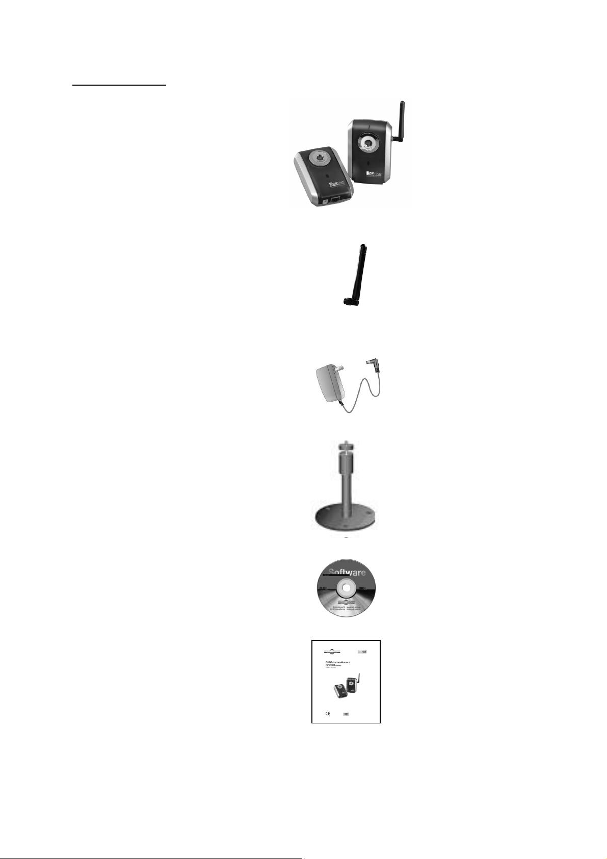
Scope of delivery
CMOS network camera
TV7203 / 7204
Antenna (only TV7204)
Transformer
Camera stand
Software CD
Installation instructions (on CD)
5
Page 6
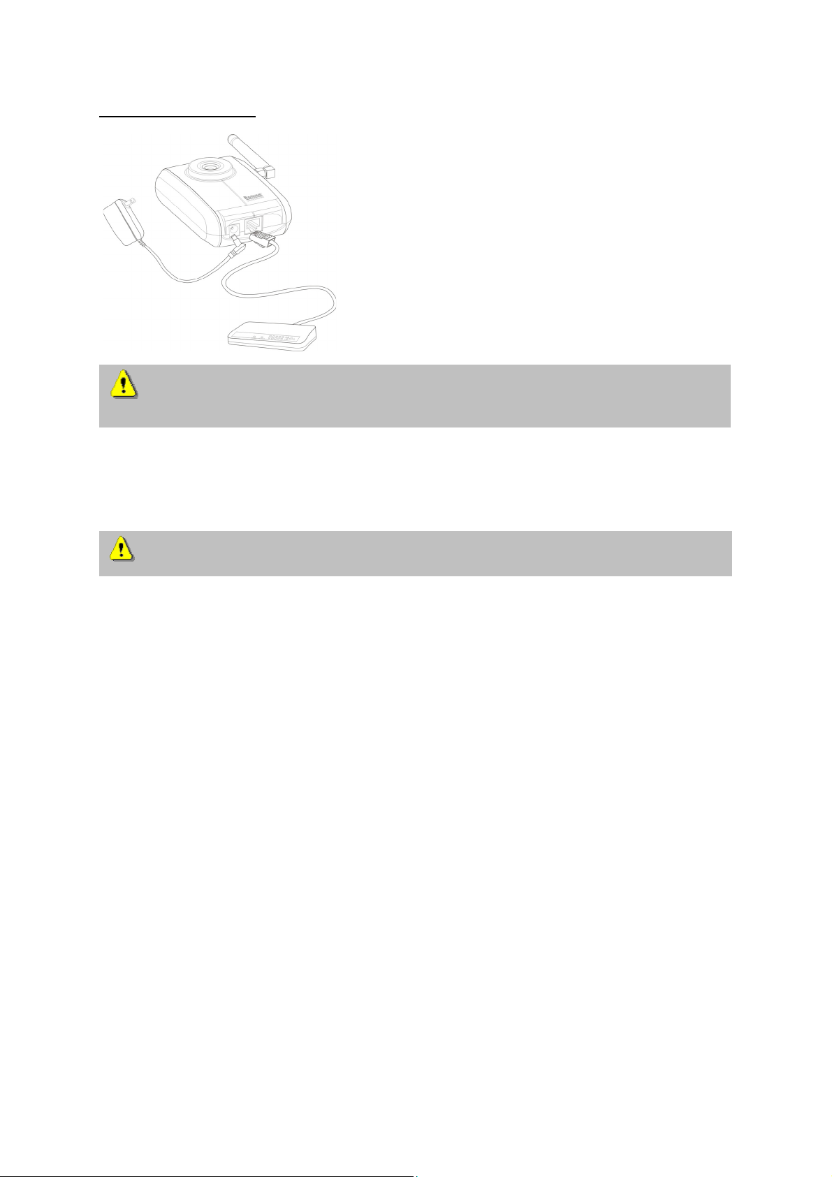
Hardware installation
To prevent the risk of electric shock, first connect the socket of the transformer to the CMOS-
network camera before inserting the transformer into the mains socket.
When you switch on, the blue LED on the front lights up and the start procedure begins. During the
start procedure, the blue and red LEDs are both active. This state continues until an IP address is
defined. After you define the IP address, the LED flashes once a second. For troubleshooting hints,
see Appendix.
Consult your dealer for the correct installation of peripheral devices.
The CMOS network camera first tries to address the wired Ethernet. If it cannot reach this, the camera
tries to reach the wireless network (WLAN). During the search and connection process to the wireless
access point, the red LED on the network camera flashes once a second. The red LED remains in this
state until the connection to an access point is established. During operation in the WLAN or wired
mode, the green LED flashes constantly once a second to show this activity.
Installation in the Ethernet
Make sure that the camera is directly connected to a PC (cross-link cable) or via a switch/hub to the
network. Now connect the network adapter of the camera to the mains network. When the camera is
correctly connected to the network, the blue LED on the front lights constantly. If no network is
available, the camera switches to WLAN mode.
Installation in the WLAN
If the camera is supplied with electricity and no Ethernet is available, the camera switches to WLAN
mode and searches for an access point with the name “default”. This name is known as the SSID
(Service Set Identifier). If an access point with the SSID “default” is found, the LED on the front lights
blue.
If connection with the basic settings (SSID: default) is not successful, connect the camera via a cable
to the wired network and configure it.
Make sure that all accessories and articles
listed above are present in the scope of
delivery. Depending on application, an Ethernet
cable may be required. This Ethernet cable
must meet the specifications of UTP Category
5 (CAT 5) and must not be longer than 100
meters.
6
Page 7
First access to CMOS network camera
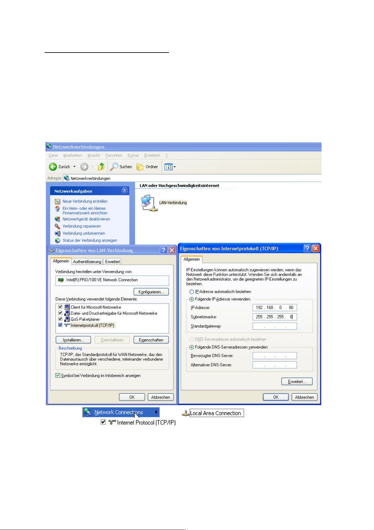
Setting the IP address
To set the IP address of the camera:
Use a network cable to connect the CMOS network camera to your computer network.
(The simplest way is to connect the CMOS network camera direct to your PC using a cross-link cable.)
If your PC is not yet integrated into a network, you first have to configure it for the network application.
Do this by opening the Properties page for your network.
(This also applies if the camera is connected to the PC via a hub or switch.)
1. Click
page of the
2. Enter a fixed IP address and subnet mask
(e.g.: 192.168.0.95 and as subnet mask 255.255.255.0).
, select and open the Properties
.
7
Page 8
The network connection of your PC is now configured.
3. Now start the Installation Wizard from the software CD supplied.
4. Follow the installation instructions of the Installation Wizard.
5. If installation is successful, start the program under Programs/Installation Wizard.
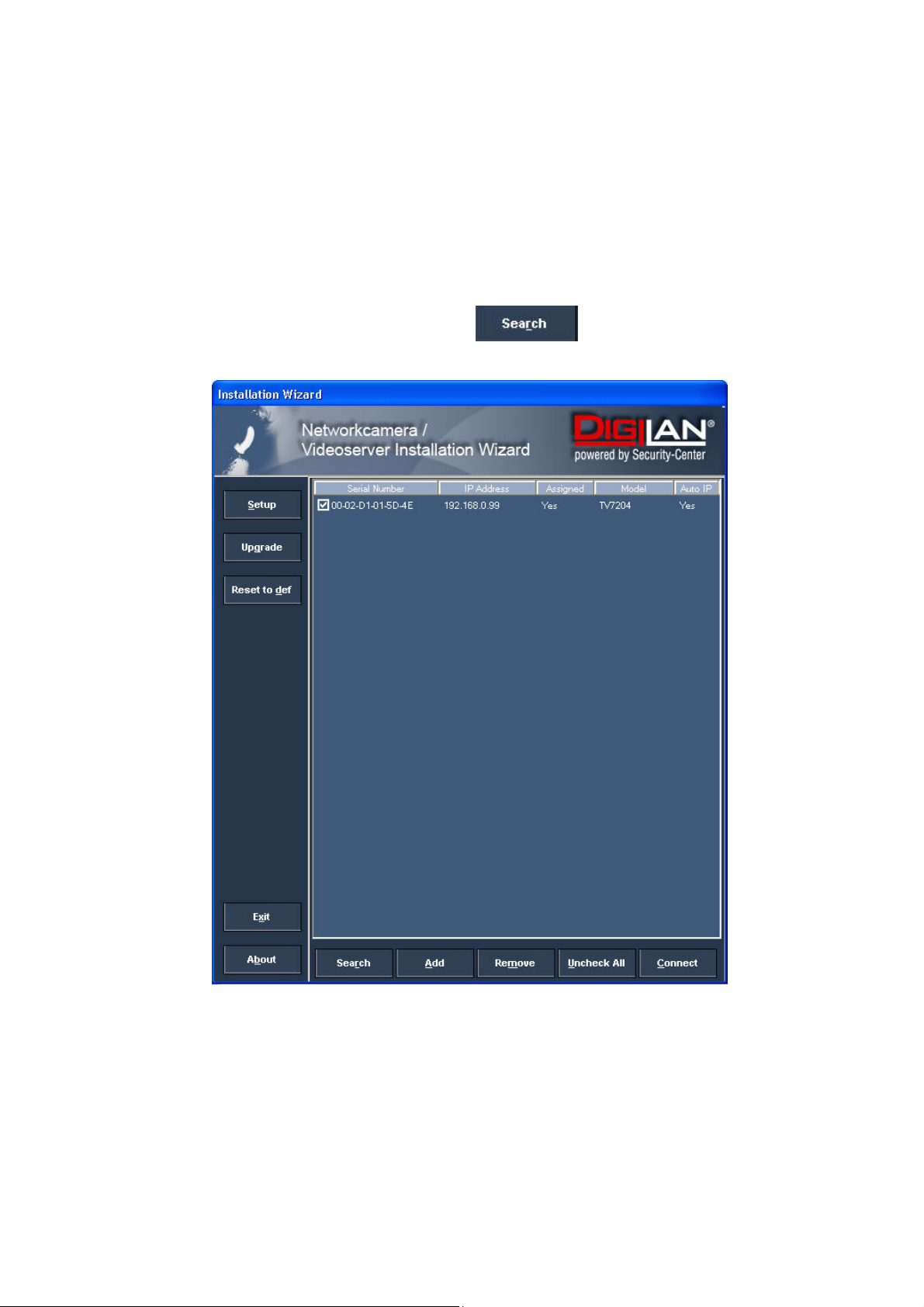
6. Following the program start, the Installation Wizard automatically searches for a connected
network camera.
7. If no camera is found in the first search, click
for a new search.
Note: If no camera is found via the manual search, change the network settings of your PC as
described in the instructions.
8
Page 9
8. Select one of the camera models found.
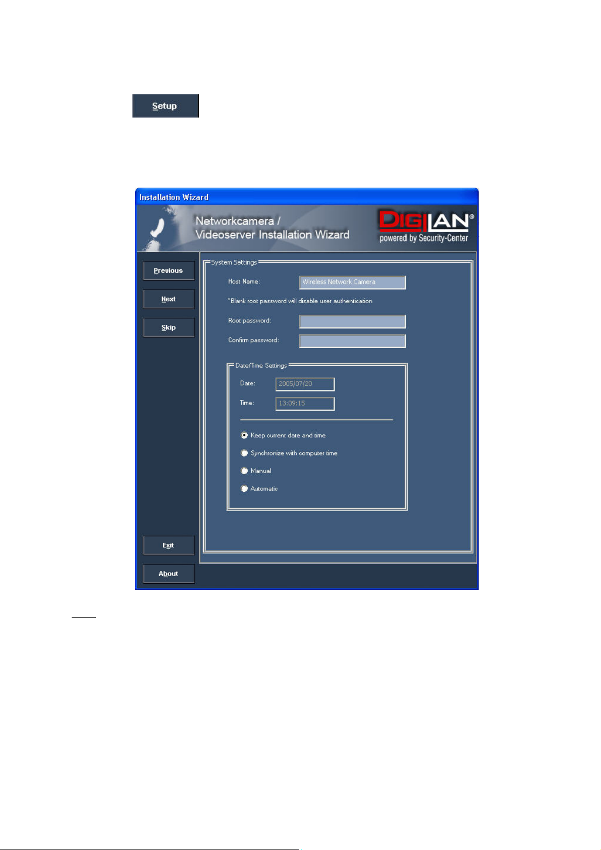
9. Click to enter camera setup mode. If you have to enter a password, use the
device serial number (no spaces, uppercase letters only). You can change the hostname, the
administrator password and the date/time settings of the camera. If you cannot access the
settings, check the IP addresses of your network adapter and your network camera. The IP
addresses must be in the same subnet area. If necessary, change the IP address of the
network adapter (page 7).
Note:
The IP addresses shown in the “Current IP Address” field reflect those on the local network. They may
be from the DHCP server. If there is no DHCP server, the camera will try to find a free IP address (this
takes from 15 seconds to 3 minutes, depending on the LAN status). The method of finding an IP
address is seeking from 192.168.0.99, to 192.168.0.254. If any of the address inside this range is free,
the network camera will be assigned to this IP address, and its subnet mask would be 255.255.255.0.
If none of the addresses is free, the network camera will try the range from 192.168.0.2 to
192.168.0.98. After an IP address is assigned to the camera, the green status LED blinks (1/s).
Note: If no camera is found via the manual search, change the network settings of your PC as
described in the instructions.
9
Page 10
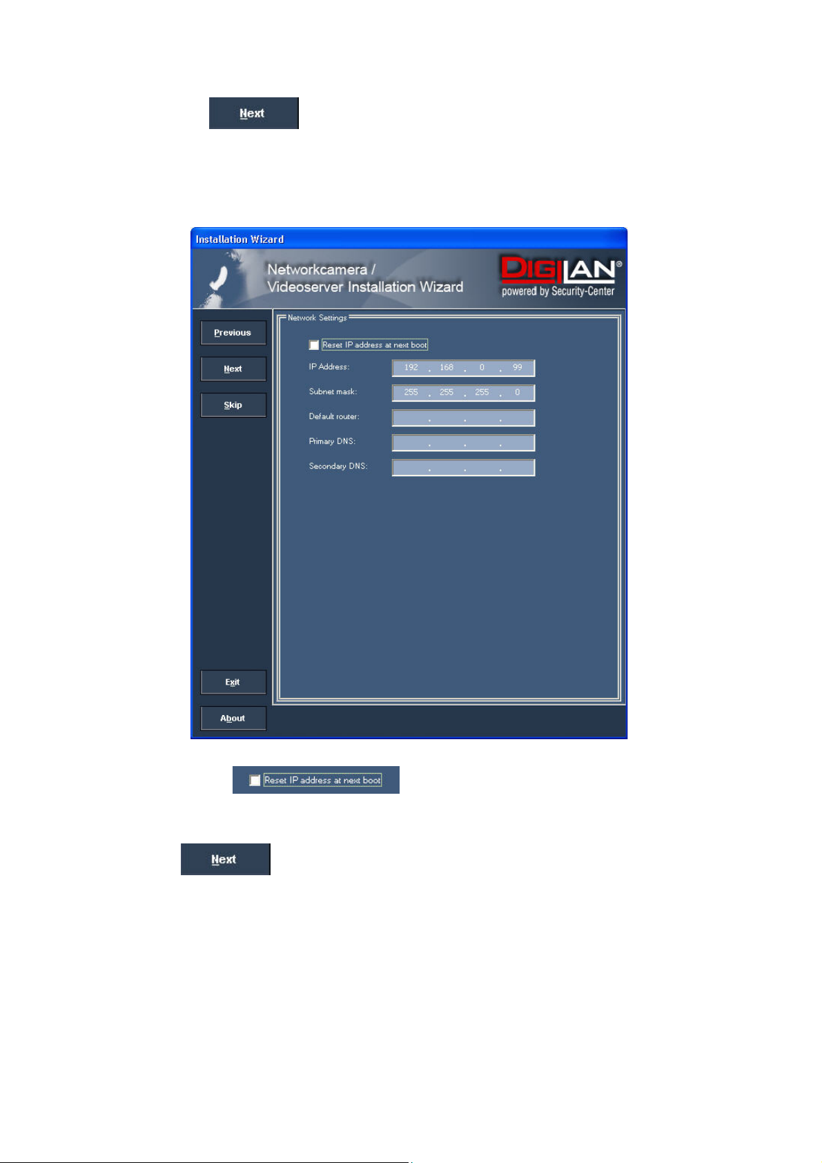
10. Now click
If you use a router in your network, enter this IP address (gateway) in the Default Router
field. For a Cross link connection from the camera to the PC you have to type in an IP address
in the same subnet (e.g. 192.168.0.1).
to change the IP address of your network camera.
11. If you disable
camera following a power failure. Otherwise, you have to reassign the IP address after every
camera restart.
12. Click
, you do not have to reassign the IP address of this
.
10
Page 11
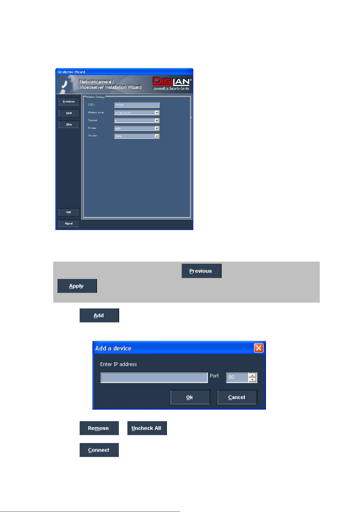
Press “Skip” to leave the “Wireless setting” unchanged this time. For further information please read
chapter “WLAN configuration”.
13. Follow the instructions on the screen to save or change your settings.
The Installation Wizard is finished. Click to change your settings. Click
to save your input and transfer it to the selected device.
14. Click
to add a network camera direct via the IP address or its domain name.
You need this only if the camera was not found by the automatic search.
15. Click
or to remove one or all network cameras from the menu.
16. Click
to set up a link to the selected network camera via the Internet Explorer.
11
Page 12
Access to the network camera via the Internet Explorer
Defining a password to prevent unauthorised access
When delivered, no administrator password is defined for the CMOS network camera.
The CMOS network camera asks for this number at the start of operation. For security reasons, the
administrator should define a new password immediately. After the new administrator password is
stored, the CMOS network camera asks for the user name and password every time it is accessed.
The administrator can define up to twenty (20) user accounts. Every user has access to the CMOS
network camera, but not to the system configuration. Some system-critical functions are reserved for
the administrator, such as system configuration, user administration and upgrading software
programs. The administrator’s user name is always root and cannot be changed. Following a
password change, the browser displays an authentication window and asks for the new password.
After changing the password, you cannot restore the original administrator password. Your only option
is to reset all default factory settings/parameters.
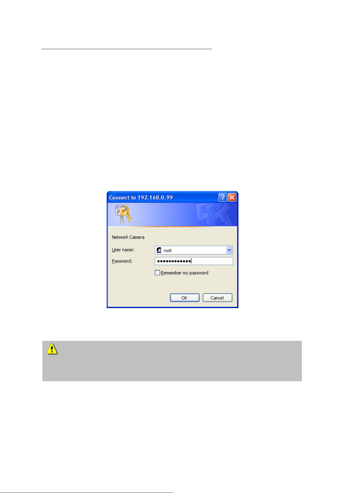
To enter a password:
Open the Internet Explorer and enter the IP address of the camera (e.g.: <http://192.168.0.99>).
You are prompted for authentication:
Î You are now connected with the CMOS network camera and can see a video stream.
Note: It may happen that your PC’s security settings prevent a video stream. You can
change the security settings to a lower level under “Tools/Internet Options/Security”. Make sure
you enable Active X Control Elements and Downloads.
12
Page 13
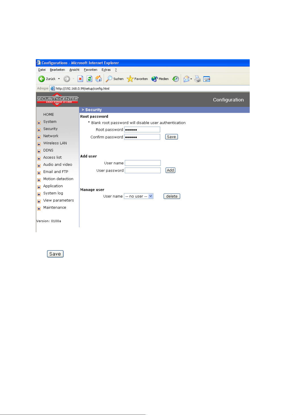
Changing the administrator password
Click “Configuration” and then “Security”.
Under “Root password”, enter the administrator password and confirm it under Confirm password.
Click
.
The new administrator password is saved.
Click “HOME” in the column on the left to exit configuration.
13
Page 14
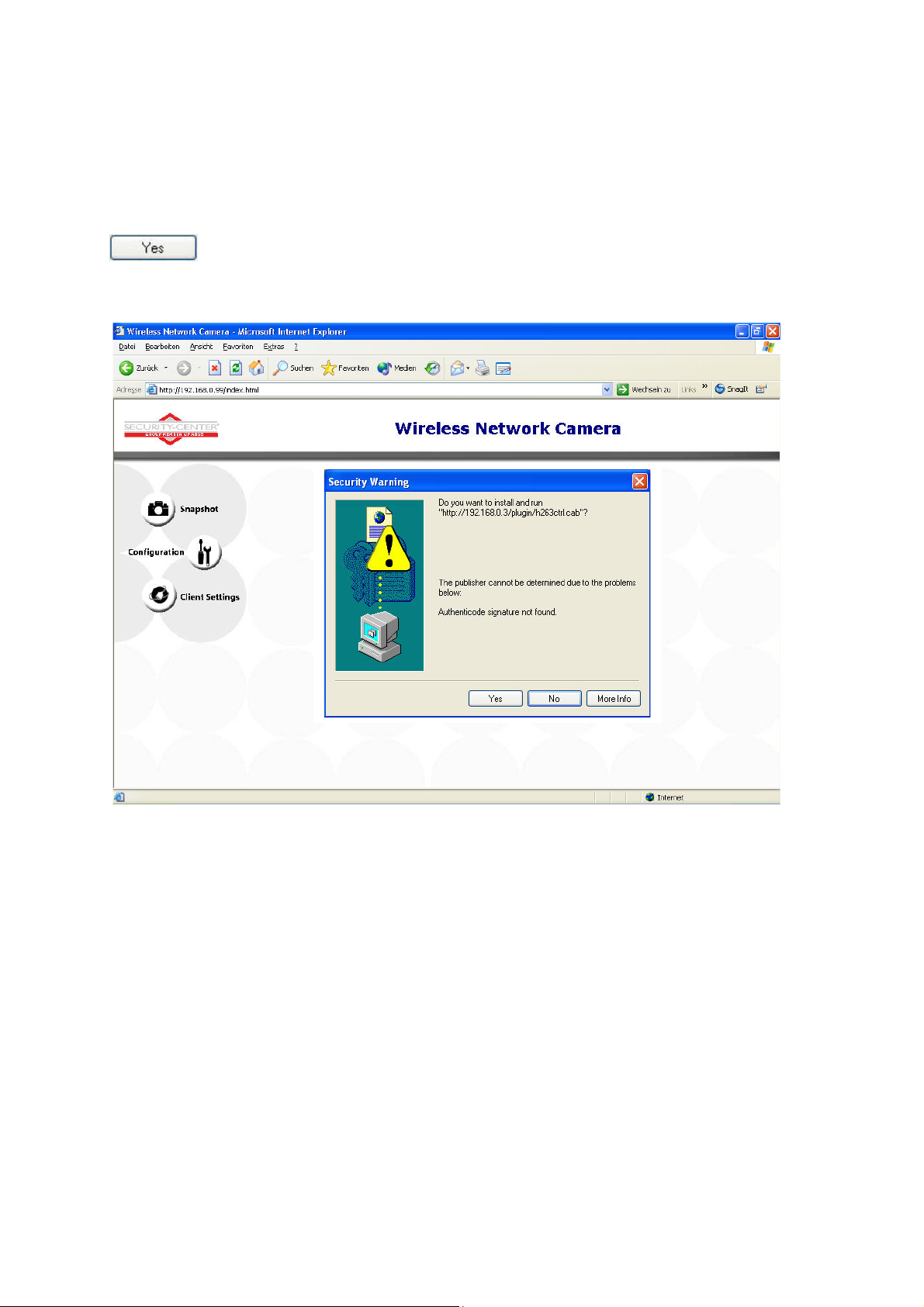
Installing the plug-in
When you first access the CMOS network camera under Windows, the web browser may ask for the
installation of a new plug-in for the CMOS network camera. This query depends on the Internet
security settings of your PC. If the highest security level is set, the PC will refuse any installation and
any attempt at execution. This plug-in is used for video display in the browser. To continue, click
. If the web browser prevents continuation of the installation, open the Internet security
settings and reduce the security level or consult the IT administrator or network administrator.
14
Page 15
Basic user functions
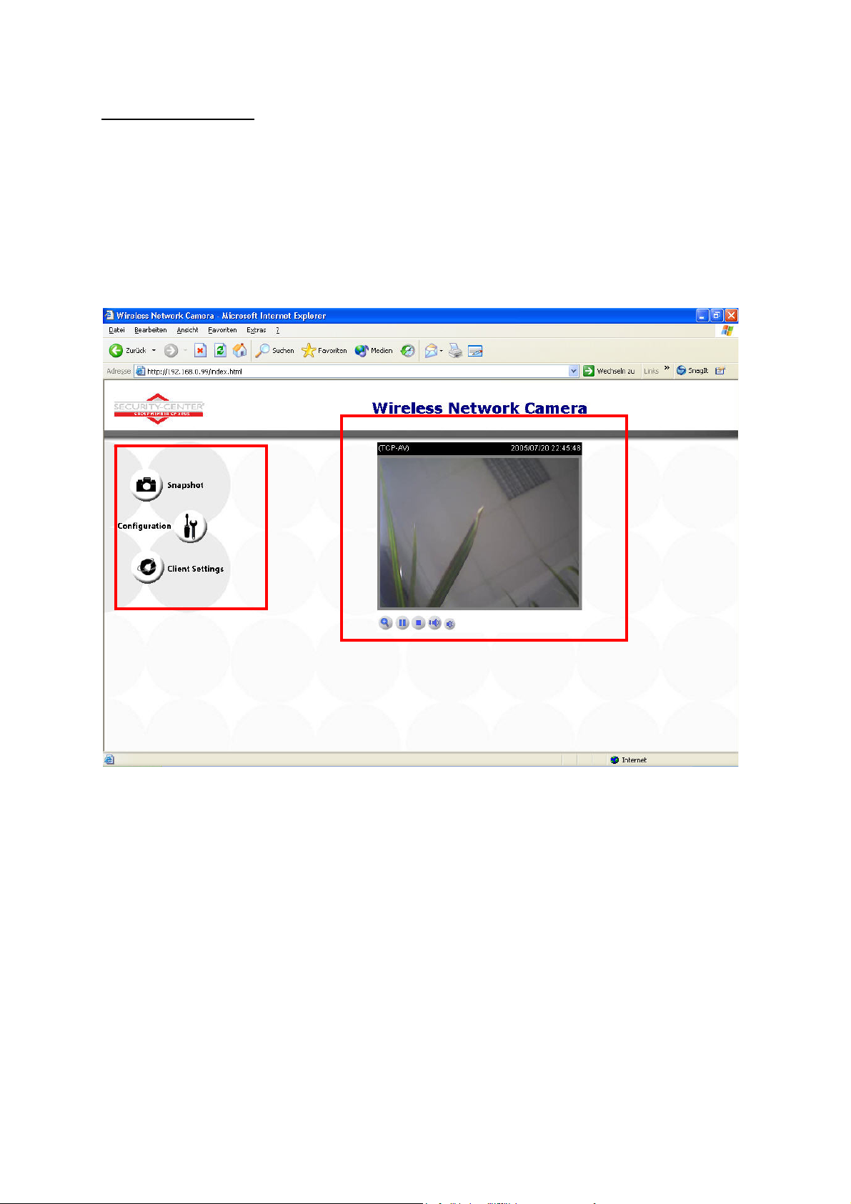
Main window and camera view
The view of the main page consists of two parts:
Configuration: You can configure the camera with these steps.
Camera view: Camera video stream
Click the configuration link on the left of the picture to open the configuration page.
15
Page 16
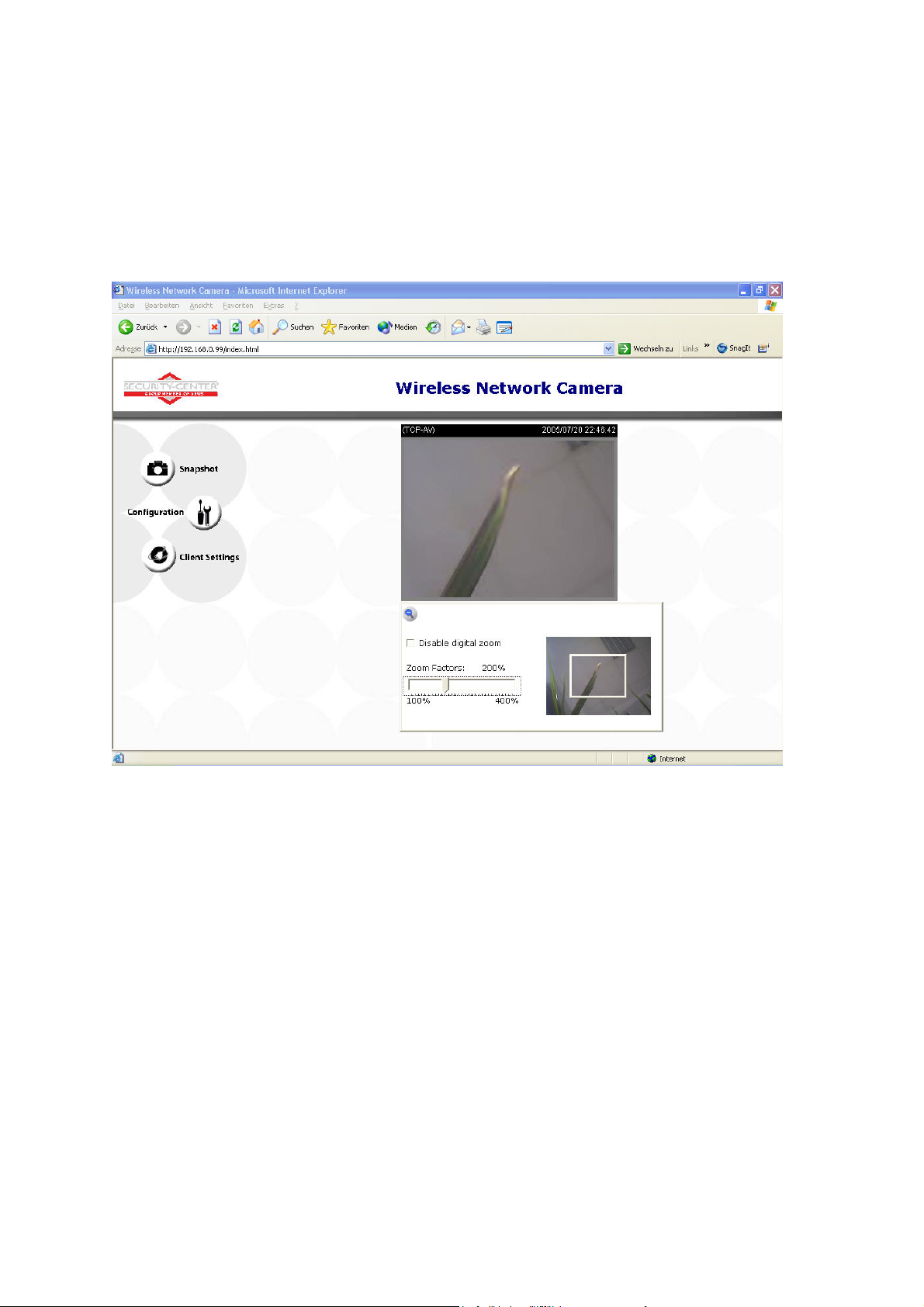
Digital Zoom and Snapshot
Click the magnifying glass under camera view. The control field for digital zooming appears. Disable
the Disable Digital Zoom box and change the zoom factor with the slider.
Click “Snapshot”. The web browser displays a new window containing the snapshot. To save the
snapshot, either left-click it and then click the diskette icon or right-click it and select Save from the
context menu.
16
Page 17
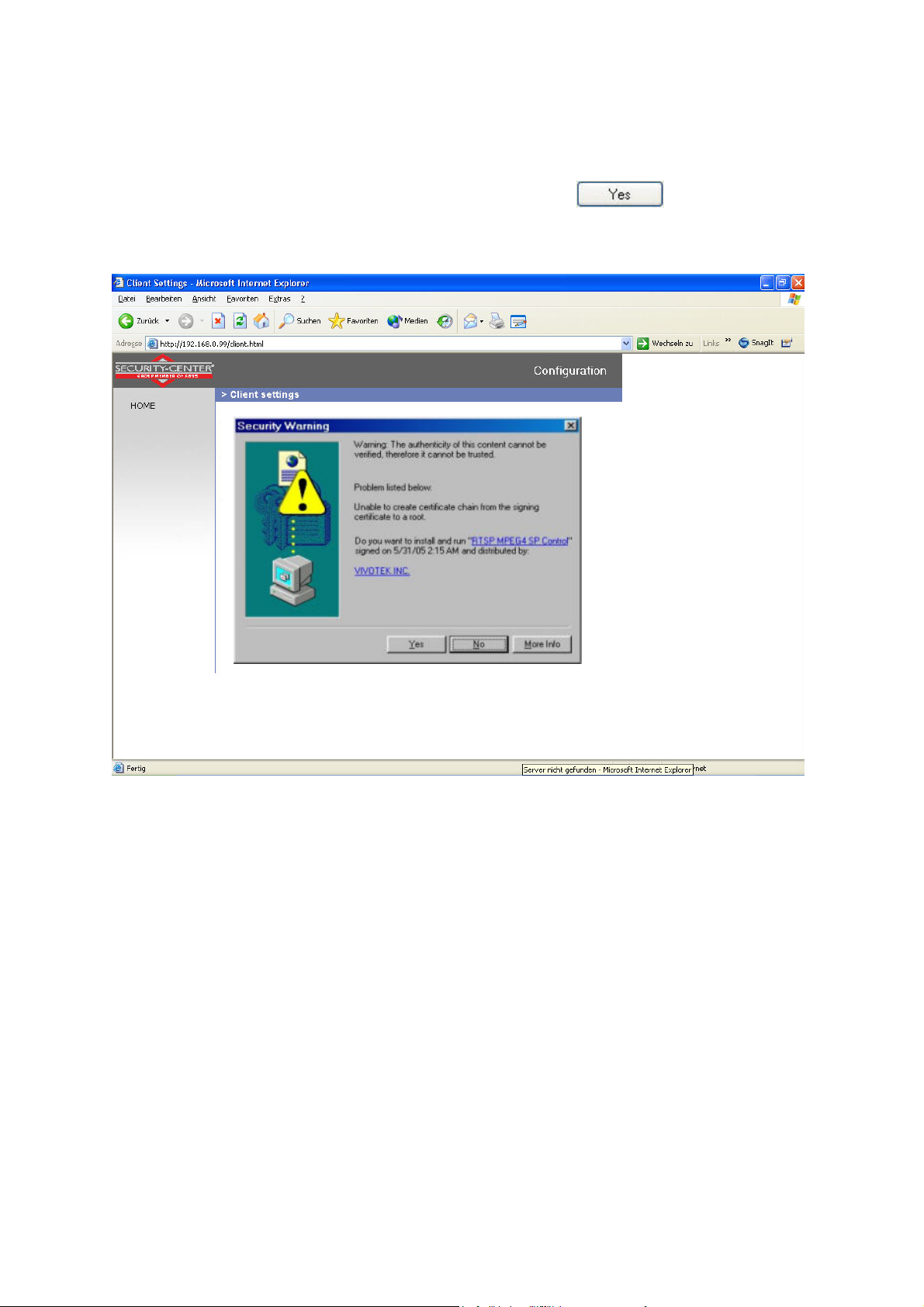
Client Settings
When you first access the Connection Type page under Windows, the web browser asks for the
installation of a new plug-in. This plug-in was registered at certification and can be used to change
parameters on the Client settings page. To install the plug-in, click
. If the web browser
prevents continuation of the installation, open the Internet security settings and reduce the security
level or consult the IT administrator or network administrator.
Two settings are available on the Client-Settings page. Under “Media Options”, you can disable the
audio- or video function. Under “Protokoll Options”, you can select a transmission protocol for data
transfer between the client and the server. Two protocol options are available for optimising the
application: UDP and TCP.
The UDP protocol gives you a larger number of realtime audio and video streams. However, some
data packets can be lost due to the large data volume in the network. Pictures can be unclear. The
UDP protocol is recommended if you have no special requirements.
With the TCP protocol, fewer data packets are lost and the video display is more accurate. The
disadvantage of this protocol is that the realtime stream is worse than with the UDP protocol.
17
Page 18

The selection of the client is normally recommended in the following order: UDP – TCP. When the
CMOS network camera has been successfully connected, the “Protocol Options” box shows the
selected protocol. The selected protocol is registered in your PC and used for the next connection.
After changing the network environment or if you want to search again for the CMOS network camera
using the web browser, select the UDP protocol manually, save it and then return to “HOME” to set up
the connection again.
<url> http://<Network Camera>/protocol.html
Network Camera is the original IP address or the hostname of the CMOS network camera.
18
Page 19

Administrator settings
Configuration / video
Best performance is produced by the maximum frame rate with best video quality and minimum
network bandwidth. The three factors “Max frame rate”, “Constant bit rate” and “Fixed quality” on the
video configuration page are interrelated.
Mobile access to the CMOS network camera
Many modern mobile telephones support access to MPEG4 videostream and GSM-AMR audio data.
Due to restricted bandwidth, only a maximum resolution of 176x144 pixels is supported. You should
therefore select “Configuration for mobile access”, and all necessary parameters are adjusted
accordingly.
For high frame rates
To obtain a good visual realtime effect (more than 20 frames/s), the network bandwidth must be
sufficiently large. If the network bandwidth is higher than 1 Mbps, the value for the “Constant bit rate”
must be set to 1000Kbps or 1200Kbps and the “Fixed quality” to the highest quality. In the PAL
system, the maximum frame rate is 25, and in the NTSC system, 30 frames per second. If your
network bandwidth is more than 384Kbps, you can fix the bit rate according to your bandwidth and the
maximum frame rate to 25 or 30 fps (frames per second). If the pictures in your environment are
changed drastically, you can reduce the maximum frame rate to 20 frames per second to set the data
transmission rate lower. This gives you a better video quality, and the human eye cannot distinguish
between 20, 25 and 30 frames per second. If the network bandwidth is less than 384 Kbps, adjust the
“Constant bit rate” according to the bandwidth and try to get the best performance by fine-tuning the
“Max frame rate”. In a “slow” network, a high frame rate results in unclear, distorted images. Another
way to improve quality is to select “160x120” in the “Size” option, or “320x240” for a larger view of the
pictures. Video quality also depends on the number of users in the network. Performance can also be
affected by a bad connection and by a restriction of the network burst.
19
Page 20

For higher-quality pictures
For best video quality, set “Fixed quality” to “Detailled” or “Excellent” and the “Max frame rate” so that
it corresponds to the bandwidth of your network. If your network is slow and you get “broken” images,
go to the TCP protocol under Connection Type and select a more suitable transmission mode.
Pictures can also be affected by a time delay due to a slower connection. The more users in the
network, the greater this time delay.
For high frame rates with high-quality pictures
If you have a broadband network, set “Constant bit rate” to or higher and leave “Constant bit rate”
unchanged. You can also set the bandwidth according to the actual network speed or the frame rate.
Start with 30 frames per second and reduce this setting until you get the best performance. However,
do not reduce it to less than 15 frames per second. If the picture quality is not improved, select a lower
setting for “Constant bit rate”.
Protecting the CMOS network camera with a password
Root password
The CMOS network camera is supplied with no password defined. Using this password, all users have
access to the CMOS network camera, including its configuration, as long as they know the IP address.
If other users are to have access to the CMOS network camera, you should therefore assign a
password to the camera. To activate protection, enter a new password. The administrator is identified
with this password.
20
Page 21

Opening accounts for new users
Under “Configuration”, select “Security”. Now go to the “Add user” section.
Add an account with user name and password for a second user. You can define up to twenty
accounts for other users of the CMOS network camera. The camera checks only the access
permission of the corresponding user name and password. This means that two or more users can
use the same account at different levels.
Setting up a surveillance application
The administrator can use the built-in motion sensor for monitoring and signalling changes to the
picture. Snapshots of events can be sent to an e-mail address or to an FTP server. For this purpose,
settings have to be made under the configuration points “Network”, “Motion sensor” and “Application”.
For detailed information, see “System configuration”.
Updating the software version
You can download the latest software from the website. A user-friendly update wizard is provided for
updating the CMOS network camera software (Installation Wizard / Upgrade). Only the administrator
can start the update function. To update the system:
1. Download the firmware file with the name xxx.pkg from the corresponding products folder.
2. Start the update wizard and follow the instructions.
3. The complete procedure finishes in a few minutes, and the system is automatically rebooted.
You can also update the software via the menu item Configuration / management of the CMOS
network camera.
If there is a power failure during the write process of the flash memory, the program in the
memory of the CMOS-network camera may be irreparably damaged. If the security network
camera cannot be correctly restarted following the update, consult your dealer’s technical support.
21
Page 22

System configuration
Only the administrator has access to system configuration. The following sections explain each
element in the left column. Specific tasks on the Options page are printed bold. The administrator can
enter the URL under the picture to jump direct to the pictures page of the configuration.
<URL>http://”Network Camera”/setup/config.html
<Network Camera> is the domain name or original IP address of the CMOS network camera.
<URL>http://”Network Camera”/setup/system.html
<Network Camera> is the domain name or original IP address of the CMOS network camera.
22
Page 23

System
„Host name“ The text represents the title of the homepage.
„Turn off the LED indicator“ Select this option to switch off the LED on the front of the camera. This
prevents other persons knowing that the camera is in use.
„Keep current date and time“ Click this option to keep the current date and time of the CMOS
network camera. An internal realtime clock stores the date and time after the system is switched off.
„Sync with computer time“ Synchronises the date and time of the CMOS network camera with the
local computer. The read-only date and time of the PC are displayed following updating.
„Manual“ Sets the date and time according to the administrator’s input. Note the date/time format
when entering in the respective fields.
„Automatic“ Synchronises the date and time with the NTP server via the Internet every time the
CMOS network camera is switched on. This is not possible if the respective time server cannot be
reached.
„NTP server“ Assigns the IP address or the domain name of the time server. If you leave this text box
empty, the CMOS network camera is connected to the default time servers.
„Time zone“ Sets the time according to the time server for local settings.
“Update interval” Select hourly, daily, weekly or monthly update with the time on the NTP server.
Don’t forget to click “Save” to make your settings take effect; otherwise, the time is not synchronised.
Security
„Root password“ For changing the administrator password by entering a new password. For security
reasons, the passwords entered are represented by asterisks. After “Save” is clicked, the web browser
prompts the administrator to enter the new password for accessing the network camera.
„Add user“ Enter the new user name and password and click “Add”. The new user is displayed on the
list of user names. Up to twenty user accounts can be defined.
„Delete user“ Open the list of user names, select a user and click “Delete” to delete this user.
<URL> http://<Netzwerkkamera>/setup/security.html
<Network Camera> is the domain name or original IP address of the CMOS network camera.
23
Page 24

Network
All changes made on this page cause a system reboot so that they can take effect. Make sure that the
fields are correctly filled before you click “Save”.
Network connection
“LAN” The default is LAN. Use this setting if the camera is connected to a LAN. You also have to
make other settings such as the IP address or the subnet mask.
“PPPoE” Use this setting if the camera is connected directly to a DSL modem. You will receive a user
name and password from your ISP (Internet Service Provider).
“Get IP address automatically” At every restart of the CMOS network camera, an IP address is
assigned.
“Use fixed IP address” The network data such as the IP address is defined here.
“IP address” This is needed for network identification.
“Subnet mask” Defines whether the destination is in the same subnet. The default value is
“255.255.255.0”.
“Default router” Gateway for transmitting pictures to another subnet. An invalid router setting
prevents transmission to these destinations in different subnets. For a Cross link connection from the
camera to the PC you have to type in an IP address in the same subnet (e.g. 192.168.0.1)
“Primary DNS” Server of the primary domain name with which the hostnames are converted into IP
addresses.
“Secondary DNS” Server of the secondary domain name for generating a reserve copy of the
primary DNS.
“Enable UPnP presentation” This enables Universal Plug and Play. This is an extension of the PnP
standard to network environments.
“Enable UPnP port forwarding” This enables Universal Plug and Play port forwarding for network
services.
“PPPoE” If using the PPPoE interface, fill in the following settings from ISP: user name, password,
password confirmation
HTTP:
“HTTP port” This port can be different from the standard port 80 (80; or 1025 to 65535). If this port is
changed, users must be informed to ensure a successful connection. Example: If the administrator
changes the HTTP port of the CMOS network camera with the IP address 192.168.0.99 from 80 to
8080, users have to enter “http://192.168.0.99:8080” in the web browser instead of
“http://192.168.0.99”.
24
Page 25

RTSP streaming:
“RTSP-Authentication” Enable the authentication of RTSP. On connection to an RTSP client
username and password will be checked. Note: This function must be supported by the media player
(e.g. Realplayer 10.5)
“Access name” The access name for establishing a connection from a client. Use rtsp://<IP
address>:RTSP-port/<access name> to establish a connection.
“RTSP port” This port can differ from the default Port 554 (554, or 1025 to 65535). If you change it,
note that the input format is analogue to the HTTP port.
“RTP Port for video” This can be other than the default port 5558. It must be an even number.
“RTCP port for video” This port must be RTP port for video plus 1.
“RTP port for audio” This can be other than the default port 5556. It must be an even number.
“RTCP port for audio” This port must be RTP port for audio plus 1.
“Enable multicast” This option turns on the multicast, bandwidth-conserving technology.
“Multicast group address” It specifies an arbitrary group of IP hosts that have joined the group and
want to receive traffic sent to this group.
“Multicast video port” This can be other than the default port 5560. It must be an even number.
“Multicast RTCP video port” This port must be multicast video port plus 1.
“Multicast audio port” This can be other than the default port 5562. It must be an even number.
“Multicast RTCP audio port” This port must be multicast audio port plus 1.
“Multicast TTL” Time to Live
25
Page 26

<URL> http://<Netzwerkkamera>/setup/network.html
<Network Camera> is the domain name or original IP address of the CMOS network camera.
26
Page 27

WLAN configuration
“SSID” (Service Set Identifier) The name that identifies the wireless network. The access point and
the WLAN network camera must use the name SSID. The factory setting is “default”. IMPORTANT:
The max. length is 32 characters; do not use: “ , ”, <, > and spaces.
“Wireless mode” Select one of the following:
“Infrastructure” The network camera is connected to the network via an access point.
“Ad-Hoc” In this mode, the network camera can communicate direct with another network
adapter (network card). A so-called Peer-to-Peer environment is set up.
“Channel” In infrastructure mode, the channel used is selected automatically by the camera. In AdHoc mode, the channel must be set manually according to the other network adapter.
“TX rate” Set the maximum transmission speed in the network. In the factory, the speed is set to
select automatically (“auto”), and the camera always tries to reach the highest transmission speed
according to the environment.
“Preamble” A so-called preamble is set before each data packet. This preamble is used to
synchronise the receiver and the sender. With a “short preamble”, the synchronisation length is shorter
and therefore not so secure.
“Security” Select the encryption method:
“None” No encryption selected.
“WEP” (Wired Equivalent Privacy) A 64- or 128-bit key is used for encryption (HEX or ASCII).
For communication with other equipment, these keys must be the same on both devices.
“WPA-PSK” (Wi-fi Protected Access – Pre Shared Keys) With this method, dynamic keys are
used. As encryption protocols, TKIP (Temporal Key Integrity Protocol) or AES (Advanced
Encryption Standard) can be selected. A so-called Pre-Shared Key must be defined.
“Auth mode” Authentication mode: Select one of the following methods:
“Shared” This mode permits communication only with equipment using the same WEP key.
“Open” The key is communicated over the whole network.
“Key length” Select 64 or 128 bit.
“Key format” Key format
“HEX” Hexadecimal format
“ASCII” ASCII format
“Network key” For different key formats, different key lengths are expected.
64 Bit: 10 hex digits or 5 characters
128 Bit: 26 hex digits or 13 characters
IMPORTANT: If you want to use characters 22 ("), 3C (<) or 3E (>), you cannot use ASCII
format.
“Pre-Shared-Key” Enter this key in ASCII format with a length of 8 ~ 63 characters.
Incorrect settings may prevent access to the camera. If the system can no longer be
addressed, read the notes on restoring the factory settings in the appendix.
27
Page 28

<URL> http://<Network Camera>/setup/wlan.html
<Network Camera> is the domain name or original IP address of the CMOS network camera.
28
Page 29

Enable the DDNS function
„Provider“ The provider list contains four hosts that provide DDNS services. Connect to the serviceprovider’s website to make sure that the service is available.
„Host name“ This field must be completed if you want to use the DDNS service. Enter the hostname
registered with the DDNS server.
„Username/Email“ The user name and the e-mail address must be entered in this field to set up a
connection to the DDNS server or to inform users about the new IP address. Important: If you enter a
user name in this field, you must enter a password in the next field.
„Password/Key“ To be able to use the DDNS service, enter the password or the key.
<URL> http://<Netzwerkkamera>/setup/ddns.html
<Network Camera> is the domain name or original IP address of the CMOS network camera.
29
Page 30

Access list
“Allow list” The IP list of accepted IPs is entered here and added to the access list. As a factory
default, all IPs are accepted. If necessary, delete the entire list.
“Start IP address” Enter the first address of the desired range.
“End IP address” Enter the last address of the desired range.
“Delete allow list” Delete desired ranges from the access list.
“Deny list” Define the IP lists to be blocked.
“Delete deny list” Delete blocked IP lists.
<URL> http://<Netzwerkkamera>/setup/accesslist.html
<Network Camera> is the domain name or original IP address of the CMOS network camera.
30
Page 31

Video and audio
General
“Configure for computer viewing” Configure camera for stationary access.
“Configure for mobile viewing” Configure camera for mobile access.
Video
“Video title” The text appears in the black bar above the video window with a timestamp. This
timestamp (date and time) is supplied by the CMOS network camera, and the date and time are
supplied by an integrated realtime clock.
“Color” Selects between colour and monochrome display.
“Frame size” Four options are available for the three video sizes: “160x120”, “176x144”, “320x240”
and “640x480”.
“Power line frequency” Fluorescent light pulses with the mains frequency. Adapt the mains
frequency to eliminate this pulsing in the picture.
Three parameters are available for setting the video quality.
“Max frame rate” Restricts the maximum frame rate, which can be combined with the “Key frame
interval” to optimise bandwidth use and video quality. If the user wants to define bandwidth usage
independently of the video quality, “Constant bit rate” and the desired bandwidth must be selected.
Video quality can be affected due to sending the maximum frame rate within the restricted bandwidth if
the pictures are fast-moving. To ensure video quality (quantising rate) independent of the network, a
greater bandwidth is used to be able to handle maximum frame rate during the transmission of rapidly
changing pictures.
“Flip” Rotates the video vertically.
“Mirror” Rotates the video horizontally. Select these options if the CMOS network camera is installed
upside down or back to front.
“White balance” Set the value for an optimal colour hue.
31
Page 32

Picture settings
Click “Image settings” to open another window in which you can set the “Brightness”, “Contrast”,
“Saturation” and the “Hue” of the video picture. Each field has levels from –5 to +5. To check your
settings, click “Preview”. To save the picture parameters, click “Save”. To discard your changes, click
“Restore”.
Audio settings
“Audio settings” Select the audio type and a bit rate.
“AAC” (Advanced Audio Coding) Special codec for audio data compression under MPEG4.
“GSM-AMR” (Global System for Mobile Communications – Adaptive Multi Rate) Voice codec
in GSM mobile telephone network.
Email and FTP
SMTP
If the SMTP server supports SMTP authentication, the user has to enter a valid user name and
password to send an e-mail via the server.
“Sender email address” E-mail address of sender.
st
“1
SMTP (mail) server” Domain name or IP address of the external e-mail server.
st
“1
SMTP account name” Permitted user name for external e-mail server.
st
“1
SMTP password” Permitted password for external e-mail server.
st
“1
recipient email address” E-mail address of recipients of snapshots or of the log file.
nd
“2
SMTP (mail) server” Domain name or IP address of another e-mail server (backup) if the first
server cannot be reached.
nd
“2
SMTP account name” Permitted user name for backup e-mail server.
nd
“2
SMTP password” Permitted password for backup e-mail server.
nd
“2
recipient email address” E-mail address of recipient for backup server.
32
Page 33

FTP
“Local FTP server port” This port can be different from the standard port 21. The user can set this
parameter to 1 to 65,535. If this parameter is changed, the server port of the connection must be
changed accordingly by the external FTP client program.
st
“1
FTP server” Domain name or IP address of the external FTP server. The following user settings
must be correctly configured for remote access.
st
“1
FTP user name” Permitted user name for external FTP server.
st
“1
FTP password” Permitted password for external FTP server.
st
“1
FTP remote folder” Permitted folder for external FTP server. The character set must match that of
the external FTP server. If the virtual path is not mapped, some FTP servers cannot accept a slash in
front of the path name. For details, see the instructions for the external FTP server. The folder
privilege must be open for uploading.
st
“2
FTP user name” Permitted user name for backup FTP server.
nd
“2
FTP password” Permitted password for backup FTP server.
nd
“2
FTP remote folder” Permitted folder for backup FTP server.
<URL> http://<Netzwerkkamera>/setup/mailftp.html
<Network Camera> is the domain name or original IP address of the CMOS network camera.
33
Page 34

Motion sensor
“Enable motion detection” Enables motion detection.
“New” Adds a new window. A maximum of three windows can be open simultaneously. To resize the
window or move the title bar, click the window frame, keep the mouse button pressed and drag the
window to the required size. Close the window by clicking the “x” in the top right corner.
“Save” Click this button to save window settings. A bar graph rises or falls according to the picture
variation. A green bar means that the picture variation is below the surveillance level, while a red bar
means that the picture variation is above the surveillance level. If the bar is red, the detected window
appears with a red frame. When you return to the homepage, the monitored window is hidden. As
soon as motion is detected, the red frame is displayed.
“Window name” The text appears at the top of the window.
“Sensitivity” Sensitivity in changes of picture sequence (e.g.: sensitivity high: triggering by slight
picture change).
“Percentage” Detectable object size (low: small objects are detected; high: only large objects are
detected)
This figure shows the screen after you click “Save”.
34
Page 35

Application
Snapshot
“Enable snapshot” Enables the application settings for snapshots.
Weekly schedule
“Sun”~”Sat” Selects weekdays for the following operations.
Time
“Always” Enables the application settings for sending snapshots at any time.
“From” ~ “to” Defines the period for sending snapshots.
Snapshot file name prefix
Enter a prefix for the snapshot file name.
Event reaction
“Motion detection” The snapshot is sent if motion is detected.
“Send # pre-event image(s)” Number of pre-event pictures to be sent.
“Send # post-event image(s)” Number of post-event pictures to be sent.
“Delay # second(s) before detecting the next event” The system detects no pictures before this
time has elapsed.
“Sequential” Snapshots are sent continuously at the interval entered.
Send snapshot by
“Email” Snapshots are sent to an e-mail address.
“FTP” Snapshots are sent to an FTP server.
Adds the date and time to the snapshot so that you can more easily distinguish between the file
names of snapshots either in sequential or event-controlled operation. Example:
“video@20030102030405.jpg” means that the JPEG picture was taken on January 2, 2003 at
03:04:05 (i.e., just after 3:04 am). If you omit this suffix, the file is updated with the name “video.jpg” on
the external FTP server according to the specified time interval.
35
Page 36

36
Page 37

Viewing the log file
Click this link on the configuration page to display the system log file. The contents of the file supply
useful information about the configuration and the connection following a system start. The standard of
the log file is RFC 3164. You can also send data to a log server. Enable “Remote Protocol” and enter
the IP address and the port number of the server.
Viewing parameters
Click this link on the configuration page to display all system parameter sets. The contents correspond
to those of CONFIG.INI.
Maintenance
Reboot system
Click to reboot the system.
Factory default
Click to restore the factory settings. All previous settings are discarded.
Upgrade firmware
Like an update with the installation wizard, you can update the firmware of the network camera here.
You can download the latest firmware from www.security-center.org
. Select the update file (flash.bin)
and click “Upgrade”. The update takes a short time. When you restart the camera, it is started with the
new firmware.
37
Page 38

Appendix
A. Troubleshooting
Status LEDs
Condition LED color
Loading system after power on Steady blue
During booting procedure Steady blue and red
Detecting and setting network Steady blue and blink red till IP address is
After network is setup (system up) Blink blue every second and steady red
During the upgrade firmware process Blink blue every second and fast blink red
Resetting and restoring
At the back side of the netzwork camera is a button. Press this button to reset the system or restore
the factory parameter settings. Sometimes the normal system status can be restored by a reset. If you
have further problems following a reset, restore the factory parameter settings and reinstall and
reconfigure the system.
RESET:
Press the reset button with a pointed object.
RESTORE:
1. Press the button continuously with a pointed object.
2. Wait until the LEDs blink fast.
3. Release the reset button.
confirmed
If the factory parameter settings are restored, all
the previous settings are deleted. The system can be
reset or restored.
Reset-Button
38
Page 39

B. Frequently asked questions (FAQ)
Q. What do I do if I forget my password?
A. Every access to the CMOS network camera requires an authentication. If you are one of the
managing users, ask your administrator for your password. If you are the administrator, there is no
way of reactivating the root password. The only way of accessing the CMOS network camera is to
press the reset button on the rear of the camera to restore the factory-set parameters and then
reconfigure the system.
Q. Why does no video appear from the CMOS network camera following authentication?
A. This problem can be caused by various factors:
1. If you have just installed the CMOS network camera and see no video, check the video modulation
on the configuration page.
2. Reduce the security level of the Internet Explorer to enable installation of the plug-ins.
3. If this problem recurs, the users are possibly working at a higher level than is permitted by the
system.
Q. What is the plug-in for?
A. The plug-in provided by the CMOS network camera is used for showing video streams in the
Internet Explorer. If your system does not permit the installation of plug-in software, reduce the
security level of the web browser. Consult your network administrator.
Q. Why is there a difference between the timestamp and the system time of the PC/notebook?
A. The timestamp is based on the system time of the CMOS network camera. This is supplied by an
internal realtime clock and can automatically be synchronised with a time server if the CMOS network
camera is connected to the Internet and the function is enabled. Differences of an hour or more are
caused by the time zone setting.
Q. Why is the picture not refreshed regularly?
A. If you use a modem, the bandwidth of the PPP connection is much less that with an Ethernet
connection. If the timestamp difference is unstable, reduce the UART FIFO for reception and
transmission under Modem Properties in the Control Panel. If you use the Ethernet, the reason may
be the length of time required to store snapshots in memory after an event occurs.
Q. How many users can watch the video simultaneously?
A. The number of users is restricted to 20. However, the video quality depends on the network
bandwidth.
Q. How fast is the video rate of the CMOS network cameras?
A. The MPEG4 Codec can internally process 30 frames a second. However, the overall quality
depends on various coefficients.
1. Data throughput in the network
2. Shared bandwidth
3. Number of users
4. The visible “complicated” objects result in large image files.
5. The settings on your PC that are responsible for displaying pictures.
The transmission rate of a normal local network can reach over 200 kilobytes per second and
approximately 10 to 20 frames per second.
Q. How can I keep access to video streams of the CMOS network camera as secure as possible?
A. The CMOS network camera was developed for surveillance purposes and has many flexible
interfaces. User authentication and special confirmation during installation can prevent unauthorised
access to the CMOS network camera. You can also change the HTTP port to a non-public number.
Check the system log for abnormal activities and their causes.
Q. How fast can the CMOS network camera check the state of the digital inputs?
A. The CMOS network camera checks the input state in less than half a second. However, to avoid the
conditions of a repeated check and ensure a correct functioning of equipment connected to the digital
outputs, the CMOS network camera delays for 3 seconds after each adaptation of the condition. You
can modify this according to your own specific applications. During this period, other conditions are
ignored.
39
Page 40

Q. Why is access to the CMOS network camera not possible while I am setting options in the
application?
A. If the CMOS network cameras are started by events, snapshots need more time since they are
written to memory. If the events occur too often, the system is constantly trying to store the pictures. If
an event occurs very frequently, use sequential mode or an external recording program to record the
pictures. If you want to access the pictures via FTP, the parameter can be set lower since FTP
responds faster than the web. If the system is busy with configuration, press the reset button to restore
the factory settings and store the system.
Q. The camera was correctly configured, but access to the camera via the http protocol or the RTSP
protocol is denied.
A. Make sure that the corresponding ports (default: Port 80 or 554) in any routers used or the firewall
are released (shared). Test the network protocol “Ping” (Windows command line input: ping <IP
address>).
Q. The network camera is connected to the network via a router, but access to the camera is denied.
A. If you want to connect the camera via a router (gateway), you have to define the gateway IP
(standard router). You can only do this if you first connect the camera direct via a cross-link cable and
then configure it.
Q. The network camera is located behind a router with a local IP. How can I access this camera from
the Internet?
A. The router receives a public IP, accessible to anyone, when you dial via the modem (e.g. DSL).
Forwarding – e.g., of an http query from the Internet – is directed first to this public IP. The router must
now be configured so that this query is forwarded to the local IP. Look up the following terms in your
router manual: NAT (Network Address Translation, IP forwarding, IP Server).
40
Page 41

C. URL-Commands
For some customers who already have their own web site or web control application, the Network
Camera can be easily integrated through convenient URLs. This section lists the commands in URL
format corresponding to the basic functions of the Network Camera.
Get server parameter values
Note: This request require administrator access
Method: GET/POST
Syntax:
http://<servername>/cgi-bin/admin/getparam.cgi?[<parameter>]
[&<parameter>…]
where the <parameter> should be <group>[_<name>] or <group>[.<name>] If you do not specify the
any parameters, all the parameters on the server will be returned. If you specify only <group>, the
parameters of related group will be returned.
When query parameter values, the current parameter value are returned.
Successful control requests returns parameter pairs as follows.
Return:
HTTP/1.0 200 OK\r\n
Content-Type: text/html\r\n
Context-Length: <length>\r\n
\r\n
<parameter pair>
where <parameter pair> is
<parameter>=<value>\r\n
[<parameter pair>]
<length> is the actual length of content.
Example: request IP address and it’s response
Request:
http://192.168.0.123/cgi-bin/admin/getparam.cgi?network_ipaddress
Response:
HTTP/1.0 200 OK\r\n
Content-Type: text/html\r\n
Context-Length: 33\r\n
\r\n
network.ipaddress=192.168.0.123\r\n
Set server parameter values
Note: This request require administrator access
Method: GET/POST
Syntax:
http://<servername>/cgi-bin/admin/setparam.cgi? [nosync=<value>&]<parameter>=<value>
[&<parameter>=<value>…][&return=<return page>]
parameter value description
<group>_<name>. value to assigned Assign <value> to the parameter <group>_<name>..
return <return page> Redirect to the page <return page> after the parameter
is assigned. The <return page> can be a full URL path
or relative path according the the current path. If you
omit this parameter, it will redirect to an empty page.
41
Page 42

(note: The return page can be a general HTML
file(.htm, .html) or a Vivotek server script executable
(.vspx) file. It can not be a CGI command. It can not
have any extra parameters. This parameter must be
put at end of parameter list)
Return:
HTTP/1.0 200 OK\r\n
Content-Type: text/html\r\n
Context-Length: <length>\r\n
\r\n
<parameter pair>
where <parameter pair> is
<parameter>=<value>\r\n
[<parameter pair>]
Only the parameters that you set and readable will be returned.
Example: Set the IP address of server to 192.168.0.123
Request:
http://myserver/cgi-bin/admin/setparam.cgi?Network_IPAddress=192.168.0.123
Response:
HTTP/1.0 200 OK\r\n
Content-Type: text/html\r\n
Context-Length: 33\r\n
\r\n
network.ipaddress=192.168.0.123\r\n
Available parameters on the server
NOTE: The bold characters in table are the default value of each parameter.
Group: System
NAME VALUE DESCRIPTION
hostname
(r/w)
(r/w)
date
(r/w)
time
(r/w)
ntp
(r/w)
timezone
(r/w)
updateinterval
(r/w)
<text string shorter than 40
characters>
0 Do not turn off the led indicator ledoff
1 Turn off the led indicator
<yyyy/mm/dd> year, month and date separated by slash.
<keep> keep date unchanged
<auto> Using NTP to sync date/time automatically
<hh:mm:ss> hour, minute and second separated by
<keep> keep date unchanged
<auto> Using NTP to sync date/time automatically
<domain name or IP
address>
-12 ~ 12 time zone, 8 means GMT +8:00
0 ~ 2592000 0 to Disable automatic time adjustment,
host name of server
<<Wireless>Network Camera >
colon.
NTP server
<skip to invoke default server>
<8>
otherwise, it means the seconds between
NTP automatic update interval.
<0>
serialnumber
(r)
firmwareversion
(r)
<mac address> 12 characters mac address without hyphen
connected
<text string shorter than 39
characters>
The version of firmware, including model,
company, and version number
42
Page 43

restore
(w)
0 Restore the system parameters to default
value.
Positive integer Restore the system parameters to default
value and restart the server after <value>
seconds.
reset
(w)
0 ~ 65535
Restart the server after <value> seconds.
-1 Not restart the server.
0 Using the profile of viewing by computer viewmode
(r/w)
1 Using the profile of viewing by mobile
phone
Group: Security
NAME VALUE DESCRIPTION
username_<1~20>
(r/w)
userpass_<0~20>
(r/w)
<text string shorter than
16 characters>
<text string shorter than
14 characters>
change user name.
<blank>
change user’s password.
The UserPass_0 is root’s password.
<blank>
userattr_<1~20>
(r)
[conf] show user’s privilege. The privilege can be
<blank> - only permit to view live media
conf – Permit to change server’s configuration
<blank>
usercount
(r)
1 ~ 21 The current account number on the server
including root.<1>
Group: Network
NAME VALUE DESCRIPTION
0 LAN type
(r/w)
1 PPPoE
pppoeuser
(r/w)
pppoepass
(r/w)
resetip
(r/w)(restart)
<text string shorter than 80
characters>
<text string shorter than 15
characters>
PPPoE account user name
<blank>
PPPoE account password
<blank>
1 enable to get ipaddress, subnet, router, dns1,
dns2 from DHCP server at next reboot
0 Using preset ipaddress, subnet, router, dns1,
dns2
ipaddress
(r/w) (restart)
subnet
(r/w) (restart)
router
(r/w) (restart)
dns1
(r/w) (restart)
dns2
(r/w) (restart)
smtp1
(r/w)
<IP address> IP address of server
<192.168.0.99>
<IP address> subnet mask
<255.255.255.0>
<IP address> default gateway
<blank>
<IP address> primary DNS server
<blank>
<IP address> secondary DNS server
<blank>
<domain name or IP address,
string shorter than 40
primary SMTP server
<blank>
characters>
mailto1
(r/w)
mailuser1
(r/w)
<string shorter than 80
characters>
<text string shorter than 63
characters>
mail recipient address
<blank>
User name of primary smtp server
<blank>
mailpass1 <text string shorter than 15 Password of primary smtp server
43
Page 44

(r/w) characters> <blank>
smtp2
(r/w)
<domain name or IP address,
string shorter than 40
secondary SMTP server
<blank>
characters>
mailto2
(r/w)
mailuser2
(r/w)
mailpass2
(r/w)
returnemail
(r/w)
localftpport
(r/w)
ftp1
(r/w)
<text string shorter than 80
characters>
<text string shorter than 63
characters>
<text string shorter than 15
characters>
<text string shorter than 80
characters>
<positive number less than
65535>
<domain name or IP address,
string shorter than 40
mail recipient address
<blank>
User name of secondary smtp server
<blank>
Password of secondary smtp server
<blank>
return email address
<blank>
FTP port
<21>
primary FTP server
<blank>
characters >
ftpport1
(r/w)
ftpuser1
(r/w)
ftppass1
(r/w)
ftpfolder1
(r/w)
<positive number less than
65535>
<text string shorter than 63
characters>
<text string shorter than 15
characters>
<text string shorter than 40
characters>
primary FTP port
<21>
user name for primary FTP server
<blank>
password for primary FTP server
<blank>
upload folder in primary FTP server
<blank>
1 Enable passive mode of primary FTP server ftppasvmode1
(r/w)
ftp2
(r/w)
0 Disable passive mode of primary FTP server
<domain name or IP address,
secondary FTP server
string shorter than 40
characters >
ftpport2
(r/w)
ftpuser2
(r/w)
ftppass2
(r/w)
ftpfolder2
(r/w)
<positive number less than
65535>
<text string shorter than 63
characters>
<text string shorter than 15
characters>
<text string shorter than 40
characters>
secondary FTP port
<21>
user name for secondary FTP server
<blank>
password for secondary FTP server
<blank>
upload folder in secondary FTP server
<blank>
1 Enable passive mode of primary FTP server ftppasvmode2
(r/w)
httpport
(r/w) (restart)
rtspport
(r/w) (restart)
videoport
(r)
audioport
(r)
accessname
(r/w)
0 Disable passive mode of primary FTP server
<positive number less than
65535>
<positive number less than
65535>
<positive number less than
65535>
<positive number less than
65535>
<text string shorter than 20
characters>
HTTP port
<80>
RTSP port
<554>
video Channel port for RTP
<5558>
audio Channel port for RTP
<5556>
RTSP access name
<live.sdp>
Group: Wireless (restart)
ssid
(r/w)
<text string shorter than 32
characters>
SSID for wireless lan settings
<default>
0 Infrastructure mode wlmode
(r/w)
1 Adhoc mode
44
Page 45

txrate
(r/w)
encrypt
(r/w)
(r/w)
keylength
(r/w)
(r/w)
keyselect
(r/w)
key1
(r/w)
key2
(r/w)
key3
(r/w)
key4
(r/w)
(r/w)
"NONE", "1M", "2M", "5.5M",
"11M", "22M"
Transmit rate in Mbps
<Auto>
for 802.11b+
"NONE", "1M", "2M", "5.5M",
"11M", "6M", "9M", "12M",
"18M", "24M", "36M", "48M",
"54M", "Auto" for 802.11g
0 None data encryption
1 WEP data encryption
2 WPA-PSK data encryption
Open Open mode authmode
Shared Shared mode
(64, 128) for 802.11g Key length in bits
<64>
HEX Key1 ~ Key4 will be represented in HEX format keyformat
ASCII Key1 ~ Key4 will be represented in ASCII format
1 ~ 4 Default key number
<1>
<text string shorter than 58
characters> (depends on
WEP key1 for encryption
<0000000000>
keyformat & keylength)
<text string shorter than 58
characters> (depends on
WEP key2 for encryption
<0000000000>
keyformat & keylength)
<text string shorter than 58
characters> (depends on
WEP key3 for encryption
<0000000000>
keyformat & keylength)
<text string shorter than 58
characters> (depends on
WEP key4 for encryption
<0000000000>
keyformat & keylength)
TKIP TKIP data encryption algorithm for WPA-PSK algorithm
AES AES data encryption algorithm for WPA-PSK
presharedkey
(r/w)
<text string shorter than 58
characters>
WPA-PSK key for encryption
<00000000>
Group: IPFilter
NAME VALUE DESCRIPTION
allowstart_<0~9>
(r/w)
allowend_<0~9>
(r/w)
denystart_<0~9>
(r/w)
denyend_<0~9>
(r/w)
1.0.0.0 ~ 255.255.255.255 Allowed starting RTSP connection IP address
<1.0.0.0>
1.0.0.0 ~ 255.255.255.255 Allowed ending RTSP connection IP address
<255.255.255.255>
1.0.0.0 ~ 255.255.255.255 Denied starting RTSP connection IP address
<blank>
1.0.0.0 ~ 255.255.255.255 Denied ending RTSP connection IP address
<blank>
Group: Video
NAME VALUE DESCRIPTION
text
(r/w)
<text string shorter than 14
characters>
enclosed caption
<blank>
0 MPEG4 codectype
(r/w)
keyinterval
(r/w)
1 MJPEG
1, 3, 5, 10, 30, 60, 90, 120 Key frame interval
<60>
size 1 half
45
Page 46

(r)
resolution
(r/w)
(r/w)
(r/w)
quant
(r/w)
2 half x 2
3 normal
4 normal x 2
5 double
256 This field is obsolete (use resolution)
176x144 (for mobile) Video resolution 176 x 144
160x120 Video resolution 160 x 120
320x240 Video resolution 320 x 240
640x480 (for computer) Video resolution 640 x 480
0 monochrome color
1 color
0 fix bit rate quality
1 fix quantization
1 lowest quality of video
2 lower quality of video
3 normal quality of video
4 higher quality of video
5 highest quality of video
bitrate
(r/w)
maxframe
(r/w)
(r/w) (in CMOS
version only)
whitebalance
(r/w) (in CMOS
version only)
20000 set bit rate to 20K bps
30000 set bit rate to 30K bps
40000 set bit rate to 40K bps
50000 set bit rate to 50K bps
64000 set bit rate to 64K bps
128000 set bit rate to 128K bps
256000 set bit rate to 256K bps
512000 set bit rate to 512K bps
768000 set bit rate to 768K bps
1000000 set bit rate to 1000K bps
1500000 set bit rate to 1500K bps
2000000 set bit rate to 2000K bps
3000000 set bit rate to 3000K bps
4000000 set bit rate to 4000K bps
1 set maximum frame rate to 1 fps
2 set maximum frame rate to 2 fps
3 set maximum frame rate to 3 fps
5 set maximum frame rate to 5 fps
10 set maximum frame rate to 10 fps
15 set maximum frame rate to 15 fps
20 set maximum frame rate to 20 fps
25 set maximum frame rate to 25 fps
30 (for 60Hz only) set maximum frame rate to 30 fps
50 synchronize with 50Hz utility mode
60 synchronize with 60Hz utility
0 auto white balance
1 fixed indoor(3200K)
2 fixed fluorescent (5500K)
46
Page 47

3 fixed outdoor( > 5500K)
1 flip image flip
(r/w)
0 normal image
1 mirror image mirror
(r/w)
0 normal image
1 Overlay time stamp on video imprinttimestamp
(r/w)
0 Do not overlay time stamp on video
Group: Audio
NAME VALUE DESCRIPTION
AAC4 (for computer) set codec to AAC type
(r/w)
GAMR (for mobile) set codec to GSM-AMR
16000 set AAC bitrate to 16K bps aacbitrate
(r/w)
amrbitrate
(r/w)
32000 set AAC bitrate to 32K bps
4750 set AMR bitrate to 4.75K bps
5150 set AMR bitrate to 5.15K bps
5900 set AMR bitrate to 5.9K bps
6700 set AMR bitrate to 6.7K bps
7400 set AMR bitrate to 7.4K bps
7950 set AMR bitrate to 7.95K bps
10200 set AMR bitrate to 10.2K bps
12200 set AMR bitrate to 12.2K bps
Group: Image
NAME VALUE DESCRIPTION
brightness
(r/w)
saturation
(r/w)
contrast
(r/w)
hue
(r/w)
<-5 ~ 5> Adjust brightness of image according to mode
settings. <0>
<-5 ~ 5> Adjust saturation of image according to mode
settings. <0>
<-5 ~ 5> Adjust contrast of image according to mode
settings. <0>
<-5 ~ 5> Adjust hue of image according to mode
settings. <0>
Group: CAMCTRL
NAME VALUE DESCRIPTION
panspeed
-5 ~ 5 Pan speed
(r/w)
tiltspeed
-5 ~ 5 Tilt speed
(r/w)
zoomspeed
-5 ~ 5 Zoom speed
(r/w)
autospeed
-5 ~ 5 Auto pan speed
(r/w)
dwelling
0 ~ 9999 Time to dwelling when patrol
(r/w)
presetname_<0~9>
(r/w)
presetpan_<0~9>
Text string shorter than 40
The name of preset location
characters.
-1024 ~ 1024 The pan coordinate of preset location.
(r/w)
presettilt_<0~9>
-56 ~ 144 The tilt coordinate of preset location.
(r/w)
47
Page 48

patrolname_<0~19>
(r/w)
Text string shorter than 40
characters.
The name of patrol location
Group: Motion
NAME VALUE DESCRIPTION
0 disable motion detection enabled
(r/w)
1 enable motion detection
0 disable motion window #1 winenabled_<0~2>
(r/w)
winname_<0~2>
(r/w)
winleft_<0~2>
(r/w)
wintop_<0~2>
(r/w)
winwidth_<0~2>
(r/w)
winheight_<0~2>
(r/w)
winobjsize_<0~2>
(r/w)
winsensitivity_<0~2>
(r/w)
update
(w)
1 enable motion window #1
<text string shorter than 14
characters >
name of motion window #1
<blank>
0 ~ 320 Left coordinate of window position.
<0>
0 ~ 240 Top coordinate of window position.
<0>
0 ~ 320 Width of motion detection window.
<0>
0 ~ 240 Height of motion detection window.
<0>
0 ~ 100 Percent of motion detection window
<0>
0 ~ 100 Sensitivity of motion detection window
<0>
1 Update the above motion detection
settings to take effect
Group: DDNS
NAME VALUE DESCRIPTION
enable
(r/w)
provider
(r/w)
0, 1 Enable or disable the dynamic dns.
<0>
1 ~ 6 dyndns.org (dynamic)
dyndns.org (custom)
tzo.com
dhs.org
safe100.net
dyn-interfree.it
<1>
hostname
(r/w)
usernameemail
(r/w)
Text string shorter than 127
characters.
Text string shorter than 63
characters.
Your dynamic hostname.
<blank>
Your user or email to login ddns service
provider
<blank>
passwordkey
(r/w)
Text string shorter than 20
characters.
Your password or key to login ddns service
provider
<blank>
update
0, 1 Update the above ddns settings to take effect
(w)
Group: UPNP
NAME VALUE DESCRIPTION
enable
(r/w)
0, 1 Enable or disable the UPNP presentation
service.
<1>
Group: UPNPfor
NAME VALUE DESCRIPTION
48
Page 49

enable
(r/w)
Group: App
NAME VALUE DESCRIPTION
scriptname
(r)
(r/w)
Group: Syslog
NAME VALUE DESCRIPTION
(r/w)
serverip
(r/w)
0, 1 Enable or disable the UPNP port forwarding
service.
<0>
<text string shorter than 255
characters>
0 Disable script enablescript
1 Enable script
0 disable remote log enableremotelog
1 enable remote log
<IP address> Log server IP address
File name of script
<script.vssx>
serverport
(r/w)
<514> Server port used for log
Application page CGI command
Note: This request requires administrator privilege.
Method: GET/POST
Syntax:
http://<servername>/cgi-bin/admin/gen-eventd-conf.cgi?[ snapshot_enable=<value>]
[&weekday=<value>][&time_method=<value>][&begin_time=<value>]
[&end_time=<value>]
[&ss_prefix=<value>][&trigger_type=<value>]
[&md_prenum=<value>][&md_postnum=<value>][&md_delay=<value>]
[&sq_interval=<value>]
[&send_method=<value][&ftp_suffix=<value>]
Return:
HTTP/1.0 200 OK\r\n
Content-Type: text/plain\r\n
Content-Length: <length>\r\n
\r\n
<depends on method value>
If(method == get || method == set)
{
tue=<value>\r\n
wed=<value>\r\n
…
}
Else if(method == normal)
{
Application page contents
}
parameter Value description
0 Enable snapshot application snapshot_enable
1 Disable snapshot application
weekday 0,1,2,3,4,5,6 The array indicate weekly schedule
49
Page 50

time_method
begin_time hh:mm Begin time of weekly schedule
end_time hh:mm End time of weekly schedule
ss_prefix <text string shorter than
md_win 0,1,2 The array indicate which motion windows are used
md_prenum 1~5 The numbers of snapshot before event
md_postnum 1~5 The numbers of snapshot after event
md_delay 1~999 The delay seconds for detecting next motion event
sq_interval 1~999 The interval seconds of sequential snapshot
ftp_suffix 0/1 Enable/Disable file name prefix
always 24 hours full day
interval Select begin time and end time
Snapshot file name prefix for both event and sequential
60 characters>
motion Set trigger by motion detect trigger_type
sequential Snapshot sequentially
mail Send snapshot by mail send_method
ftp Send snapshot by ftp
operation
Capture single snapshot
Note: This request require normal user privilege
Method: GET/POST
Syntax:
http://<servername>/cgi-bin/video.jpg
Server will return the most up-to-date snapshot in JPEG format. The size and quality of image will be
set according to the video settings on the server.
Return:
HTTP/1.0 200 OK\r\n
Content-Type: image/jpeg\r\n
[Content-Length: <image size>\r\n]
<binary JPEG image data>
Account management
Note: This request requires administrator privilege
Method: GET/POST
Syntax:
http://<servername>/cgi-bin/admin/editaccount.cgi
method=<value>&username=<name>[&userpass=<value>][&privilege=<value>]
[&privilege=<value>][…][&return=<return page>]
parameter value Description
method
username <name> The name of user to add, delete or edit
add Add an account to server. When using this method,
delete Remove an account from server. When using this method,
edit Modify the account password and privilege. When using
?
“username” field is necessary. It will use default value of
other fields if not specified.
“username” field is necessary, and others are ignored.
this method, “username” field is necessary, and other
fields are optional. If not specified, it will keep original
settings.
50
Page 51

userpass <value> The password of new user to add or that of old user to
modify. The default value is an empty string.
privilege
return <return page> Redirect to the page <return page> after the parameter is
<value> The privilege of user to add or to modify. The privilege
can be the addition of the following values. Ex: A user
with configure access can be assigned privilege as
privilege=conf.
conf configuration privilege
assigned. The <return page> can be a full URL path or
relative path according the the current path. If you omit
this parameter, it will redirect to an empty page.
System logs
Note: This request require administrator privilege
Method: GET/POST
Syntax:
http://<servername>/cgi-bin/admin/syslog.cgi
Server will return the up-to-date system log.
Return:
HTTP/1.0 200 OK\r\n
Content-Type: text/plain\r\n
Content-Length: <syslog length>\r\n
\r\n
<system log information>\r\n
Configuration file
Note: This request requires administrator privilege
Method: GET/POST
Syntax:
http://<servername>/cgi-bin/admin/configfile.cgi
Server will return the up-to-date configuration file.
Return:
HTTP/1.0 200 OK\r\n
Content-Type: text/plain\r\n
Content-Length: <configuration file length>\r\n
\r\n
<configuration data>\r\n
Upgrade firmware
Note: This request requires administrator privilege
Method: POST
Syntax:
http://<servername>/cgi-bin/admin/upgrade.cgi
Post data:
fimage=<file name>[&return=<return page>]\r\n
51
Page 52

\r\n
<multipart encoded form data>
Server will accept the upload file named <file name> to be upgraded the firmware and return with
<return page> if indicated.
52
Page 53

D. Technical data
- System
CPU: VVTK-1000
RAM: 32MB SDRAM
ROM: 4MB FLASH ROM
- Supported protocols
TCP/IP, HTTP, SMTP, FTP, DDNS, UPnP,
Telnet, NTP, DNS, DHCP and RTSP
- Connections
10 baseT or 100 baseT Fast Ethernet auto
negotiation
802.11g wireless LAN (only TV7204)
- Video
MPEG4 (short header mode) algorithm
JPEG for snapshots
Adjustable picture size, quality and bit-rate
Date, time and text overlay
3 motion sensor fields
Resolution
Up to 25 frames/s at 160x120
Up to 25 frames/s at 320x240
Up to 25 frames/s at 640x480
- Camera specifications
- Dimensions
114 x 73 x 35 mm (HxWxD)
- Weight
ca. 170g
- Voltage supply
Transformer included in scope of delivery
Input: 100-240V AC, 50/60Hz, 0.5A
Output: 5V DC, 2A
- Environment conditions
Temperature: 0-35°C/32-122°F
Ambient operating humidity: 90% RH
- EMI & Safety
CE, FCC
- PC system requirements
Operating system
Microsoft Windows 2000/XP
Browser
Internet Explorer 5.x or higher
Packet Video Player 3.0
Realplayer 10.5
Quicktime 6.5
1/4 inch colour HQ-CMOS sensor
Resolution: 640x480
1.5Lux/F2.0
AGC, AWB, AES
Electronic shutter: 1/60 ~ 1/15000 second
- Lens
Fixed focus with fine adjustment, 4.0mm, F2.0
- Audio
AAC, GSM-AMR
- Microphones
Omnidirectional
Frequency: 50 – 16000Hz
S/N rate: more than 60dB
- LED display
Two-colour status display
53
Page 54

E. Licence information
GNU GPL
We point at the fact that the network cameras „TV7203“ and „TV7204“ among other things include
Linux software source codes that are licensed under the GNU General Public Licence (GPL). To
assure a GPL compliant usage of the used source codes we point at the licence terms of GPL.
Licence text
The licence text of the GNU General Public Licence can be found on the included software CD in the
folder CDROM:\GNU_GPL\GPL-Licence.txt or on the Security Center Homepage under
http://www.security-center.de/software/download/GPL/GPL-licence.txt
.
Source Code
The used source codes are available on the software CD in the folder
CDROM:\GNU_GPL\GPL_Sources.zip or on the Securtiy Center Homepage under
http://www.security-center.de/software/download/GPL/GPL_sources.zip
for free download.
Operation of the total system
With a download of the software packages (source codes) it is not possible to built a running total
system. Therefor additional software applications and the network camera hardware is needed.
AMR Technology
This product includes AMR narrowband speech coding technology licensed by VoiceAge. Please refer
to http://www.voiceage.com/
for more details.
MPEG-4 AAC Technology
This product includes MPEG-4 AAC audio coding technology licensed by Via Licensing. Please refer
to http://www.vialicensing.com/
for more details.
MPEG-4 Visual Technology
This product includes one MPEG-4 encoder and one MPEG-4 decoder license. Installation of more
than one decoder is prohibited. Please contact your reseller to purchase additional decoder licenses.
THIS PRODUCT IS LICENSED UNDER THE MPEG-4 VISUAL PATENT PORTFOLIO LICENSE FOR
THE PERSONAL AND NON-COMMERCIAL USE OF A CONSUMER FOR (i) ENCODING VIDEO IN
COMPLIANCE WITH THE MPEG-4 VISUAL STANDARD ("MPEG-4 VIDEO") AND/OR (ii)
DECODING MPEG-4 VIDEO THAT WAS ENCODED BY A CONSUMER ENGAGED IN A
PERSONAL AND NONCOMMERCIAL ACTIVITY AND/OR WAS OBTAINED FROM A VIDEO
PROVIDER LICENSED BY MPEG LA TO PROVIDE MPEG-4 VIDEO. NO LICENSE IS GRANTED
OR SHALL BE IMPLIED FOR ANY OTHER USE. ADDITIONAL INFORMATION INCLUDING THAT
RELATING TO PROMOTIONAL, INTERNAL AND COMMERCIAL USES AND LICENSING MAY BE
OBTAINED FROM MPEG LA, LLC. SEE HTTP://WWW.MPEGLA.COM
54
 Loading...