

Page 1
SV
-8
ABUS TECHNOLOGIES INC.
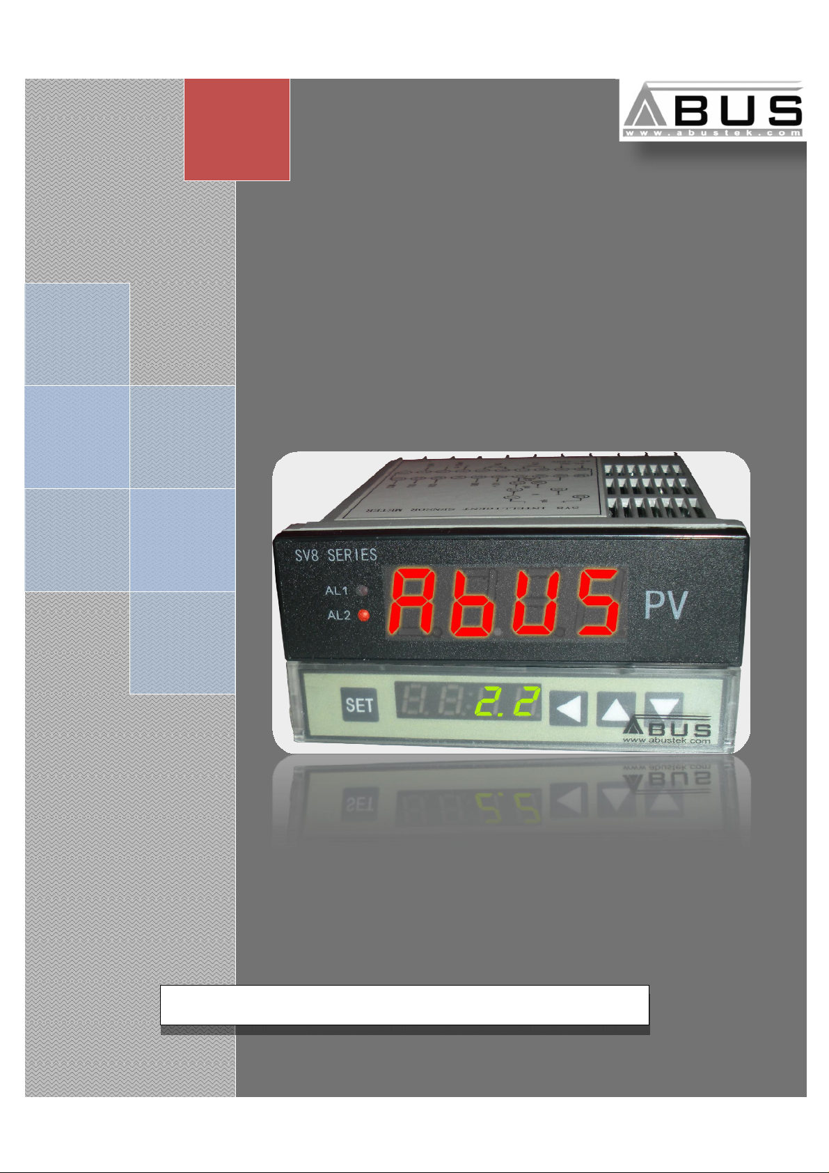
Universal Process Indicator
User Manual
Page 2

SV
WARNING
v This manual should be passed on to the end user.
v The contents of this manual are subject to change without prior notice.
v All rights reserved.
v ABUS gives no warranty of any kind with regard to this manual, including, but not limited to, fitness
for a particular purpose.
v If any question arises or errors are found, or if any information is missing from this manual, please
inform your supplier or inform at info@abustek.com.
v The specifications mentioned in this manual are limited to those for the standard type under the
specified model number break-down and do not necessarily apply for customized instruments.
v Please note that changes in the specifications, construction, or component parts of the instrument
may not immediately be reflected in this manual at the time of change.
v If the customer or any third party is harmed by the use of this product, ABUS assumes no
responsibility for any such harm owing to any defects in the product which were not predictable, or
-8
for any indirect damages.
Although Warning hazards are related to personal injury, and Caution hazards are associated
with equipment or property damage, it must be understood that operation of damaged equipment could,
under certain operational conditions, result in degraded process system performance leading to
personal injury or death. Therefore, comply fully with all Warning and Caution notices.
Information in this manual is intended only to assist our customers in the efficient operation of
our equipment. Use of this manual for any other purpose is specifically prohibited and its contents are
not to be reproduced in full or part without prior approval of Technical Communications Department,
ABUS Technologies
HEALTH AND SAFETY
To ensure that our products are safe and without risk to health, the following points must be
noted:
1. The relevant sections of these instructions must be read carefully before proceeding.
2. Warning labels on containers and packages must be observed.
3. Installation, operation, maintenance and servicing must only be carried out by suitably trained
personnel and in accordance with the information given. Any deviation from these instructions will
transfer the complete liability to the user.
4. Normal safety precautions must be taken to avoid the possibility of an accident occurring when
operating in conditions of high pressure and/or temperature.
5. Chemicals must be stored away from heat, protected from temperature extremes and powders kept
dry. Normal safe handling procedures must be used.
6. When disposing of chemicals ensure that no two chemicals are mixed.
Safety advice concerning the use of the equipment described in this manual or any relevant hazard data
sheets (where applicable) may be obtained from the Company address on the back cover, together with
servicing and spares information.
ABUS TECHNOLOGIES INC.
2
Page 3

SV
.
-8
CATALOGUE
Contents Page No.
1. Introduction
Applications
2. Presentation
Features
3. Dimensions 4
4. Ordering Details 5
5. Connections 5
6. Installation
1. Input Signal
2.
7. Configuration
1. Configuration Process
2.
8. Operation
Example for Usage
9. Maintenance
Troubleshooting
10. Safety Precautions 10
11. Warranty 10
Panel
Key Operation Instructions
4
4
4
4
6
6
6
7
7
8
9
9
9
9
ABUS TECHNOLOGIES INC.
3
Page 4

4
SV-8
1. INTRODUCTION
The SV-8 series of Universal Process Indicators are high performance
instruments used for monitoring analog signals in the vast majority of industrial and
laboratory processes. Configuration from the front panel can be easily made to accept
RT (Ω), mA, voltage or mV signals.
The retransmission of input in form of standard current or voltage signal make it
even more adaptive to the process environment, the retransmitted output signal could
be further taken to PLCs or other Analog signal processing devices such as
Recorders. Two bright 4 Digit displays are Extra Alarm and RS485 MODBUS
Communication are available as option.
Applications
process control industry the product finds use to display process parameters from various sensors such
as Pressure, Flow, Level, Temperature etc...
The product can support a wide application range to accept and display analog inputs. In
2. PRESENTATION
Features
1. Input signals mA, V, mV and RT (Ω) programmable from the front panel.
2. 2 relay alarm output free setting capacity AC 250V/3A or DC 30V/3A.
3. 4~20 mA DC Retransmission output.
4. Auxiliary output power supply 24V/12V DC max 30mA.
5. With RS-485 communication.
6. Accuracy: 0.2% FS.
7. Power supply: 85~260V AC/DC, consumption less than 5VA.
3. DIMENSIONS
All Dimensions in mm
ABUS TECHNOLOGIES INC.
Page 5

5
SV-8
4. ORDERING DETAILS
TYPE DESCRIPTION
Product SV
Size
Output
Alarm
Communication
5. CONNECTIONS
Process Indicator
8 48 x 96 x 112 mm
R
D 4~20mA DC Output
B
C
No Retransmission O/P
1 Alarm
2 Alarm
10 None
18 RS-485 Communication
Example: SV > 8 > D > C > 10
ABUS TECHNOLOGIES INC.
Page 6

6
SV-8
6. INSTALLATION
6.1 Input Signal
INPUT SIGNAL
mA 0~1 mA 0~20 mA ≤ 150 Ω 4~20mA
V ± 10V ≤ 200 K Ω 0~5V
mV -20~100mV ≤ 2 M Ω 0~50mV
MEASURING
RANGE
INPUT
IMPEDANCE
DEFAULT
SETTING
Pt (Resistance)
6.2 Panel
0~400 Ω
0~1K
0~10K
≤ 0.2 mA
≤ 0.1 mA
≤ 0.1 mA
0~400 Ω
S.NO. PARAMETERS
1 LED Up: Measuring value/ Parameter code display.
2 LED Down: Parameter value/ Input code display.
3 AL1 Alarm1 Indicator lamp.
4 AL2 Alarm 2 Indicator lamp.
5 SET Parameter select/SET key.
6 ◄ Shift Key
7 ▼ Decrease Key
8 ▲ Increase Key
ABUS TECHNOLOGIES INC.
DESCRIPTION
Page 7

7
SV-8
Power supply and self
-
examination
Alarm mode setting
INPUT TABLE REFERENCE
7. CONFIGURATION
7.1 Configuration Process
ABUS TECHNOLOGIES INC.
Page 8

8
SV-8
Adjust Setting Mode
7.2 Key Operation Instructions
1. Press SET key selecting the alarm mode or setting menu. Press ◄ key to shift to the digit that to be
modified. LED flashes, press ▼▲ key to modify, then press SET key to confirm.
2. In the menu of the alarm mode, press SET key to select LCK, when the value is 000 or 010, press
SET key for 3 seconds, entering the adjust menu.(The operation of other parameters is the same.)
3. The unit will return to measuring estate without key operation for 25 seconds.
ABUS TECHNOLOGIES INC.
Page 9

9
SV-8
8. OPERATION
Example for usage
1. Used with 2 wire transmitter. The instrument can supply DC 24V auxiliary power and isolate
analogue output 4~20mA. Select input signal mA.
2. Used with pressure sensor. The instrument can supply DC 12V auxiliary power, and the sensor
output is 2mV/V. Select input signal mV.
9. MAINTENANCE
Troubleshooting
INFORMATION
Sensor not connected or input
signal is too low.
Sensor not connected or input
signal is too high.
SPECIFICATIONS ELIMINATE
Check and connect the sensor
properly, or reset the low alarm value.
Check the parameters FL1 and FH1.
Check and connect the sensor
properly, or reset the high alarm value.
Check the parameters FL1 and FH1.
ABUS TECHNOLOGIES INC.
Page 10

SV
10. SAFETY PRECAUTIONS
1. The unit should be powered for 15 minutes before use.
2. Use in ambient temperature of 0-60˚C.
3. Avoid vibrations, shock, excessive dust, corrosive chemical materials or
gaseous environment.
4. Input wire should not be too long. If measured signal have to be far away from
the unit, please use 2-core shielded cable.
5. Use this instrument in the scope of its specifications, otherwise fire or
malfunctions may result.
6. Contact of the instrument, with organic solvents or oils should be avoided.
7. Do not turn on the power supply until all of the wiring is completed. Otherwise
electrical shock, fire or malfunction may result.
8. Do not disassemble, repair or modify the instrument.
9. All connections should be tightened properly.
10. Power supply should be constant, should not be fluctuating.
11. WARRANTY
ABUS provides the original purchaser of this instrument a one (1) year warranty
against defects in material and workmanship under the following terms:
-8
• The one year warranty begins on the day of shipment as stated on the sales bill.
• During the warranty period all costs of material and labor will be free of charge
provided that the instrument does not show any evidence of misuse.
• For maintenance, return the instrument with a copy of the sales bill to our factory.
• All transportation and insurance costs should be covered by the owner of the
equipment.
• Should any sign of electrical or mechanical shock, abuse, bad handling or misuse
be evident the warranty voids and maintenance costs will be charged.
REV 01(090410)
• Ordering details changed for better understanding.
• Improved product image updated.
ABUS TECHNOLOGIES INC.
www.abustek.com, E-Mail: info@abustek.com
ABUS TECHNOLOGIES INC.
10
 Loading...