

Page 1
Riegelschaltkontakt
RS1000
(Schließblechkontakt, Verschluss- / Schließzustandsmelder)
Montageanleitung
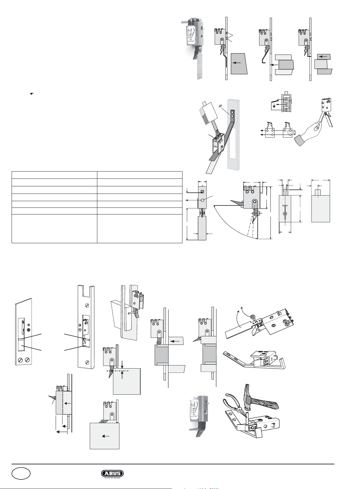
• Befestigungslage für den Riegelschaltkontakt ermitteln.
Neuheit: Montagemöglichkeit seitlich zum Riegelausschnitt! (Patent!)
• Hebelarm entsprechend den Anforderungen nach Beispiel Bild 1, 2 oder
Bild 3 anpassen bzw. Zylinderstift einsetzen für eine seitliche Montage.
• Bohrschablone an der Befestigungsstelle aufkleben und Bohrung 3,2mm
(2x) ausführen. Bild 4. Erfolgt eine Kabelanlötung, Bohrschablone für
diese Arbeitsausführung belassen!
• Bei Bedarf Anschlusskabel durch die Kabelöffnung der Haube führen.
• Bei Ausführung ohne „Anschlusskabel“ Riegelschaltkontakt auf das
abgewinkelte Teil der Bohrschablone aufstecken. Bild 4. Anschließend
Anschlusslötverbindung entsprechend der Anforderung ausführen. Bild 5
Mikroschalter-Gehäuse ist wasserdicht IP67! Anschlüsse IP 50
Gegebenenfalls Lötverbindung vor Witterungseinflüße mit einem
Schrumpfschlauch bzw. durch vergießen mit geeignetem Silikon
schützen.
• Riegelschaltkontakt und Bohrschablone entfernen.
• Eine Senkung für die Befestigungs-Senkschraube M3 herstellen.
• Klebestrip von der Bohrschablone entfernen, Riegelschaltkontakt auf die
Bohrschablone = Montagehilfe aufsetzen. Bild 6.
• Riegelschaltkontakt in die Befestigungsposition bringen.
• Mit entsprechend beigelegter Senkschraube M3 befestigen.
HINWEIS! Die korrekte Schraubenlänge errechnet sich aus der Gewindetiefe
des Riegelschaltkontakt =2mm plus der Materialstärke vom Schließblech!
Eine Schraube mit Überlänge führt zu einer Funktionsstörung!
Technische Daten VdS - Nr. G 186 105 Klasse C
Gehäuse, Feder und Hebelarm X12CrNi177 1.4310 (Nirosta/Edelstahl)
Mikroschalter (Wechsler) Goldkontakt 1 mA – 2 A / 30 V
Temperatur Bereich -40 °C bis +65 °C (VdS Klasse III)
Luftfeuchtigkeit Max. 95 % relativ
Schutzart: Mikroschalter / Anschlüsse IP 67 / IP 50 Anschl. vergossen IP67
mit Abdeckhaube IP 64
Lieferumfang:
Ausführung mit Anschlusskabel:
Kabel LIYY 3x0,14 mm
2
grau Ø3,4mm
Länge 2m verzinnt für LSA – Plus
Schneidklemmtechnik geeignet.
Riegelschaltkontakt, Abdeckhaube,
Bohrschablone, je 1 Senkschraube
DIN 965 Kreuzschlitz A2 (Edelstahl)
M3x5, M3x6, M3x8, M3x10
Zylinderstift DIN7m6 2x16 A2
Evtl.
Zugentlastung
mit
Kabelbinder
Ausführung
mit Anschlusskabel LIYY
weiß = 3
grün = 2
braun = 1
8
5
,
7
,7
8
4
3
Bild 1 Bild 2 Bild 3
Schraubenlänge
= Materialstärke
Schliießblech + 2 mm
Ø 3,2mm
Senkung 90°
Schraubenkopf
ca. Ø 5,5mm
Riegel
Riegel
Abbildung mit Anschlusskabel
Bild 4 Bild 5 Bild 6
2 x 3,2mm
3
1
3
2
2
1
<mm>
M3
5
Darstellung
nicht betätigt!
Kabel LIYY
3 = weiß
2 = grün
1 = braun
Zentrale
Einsatz Abdeckhaube (Aussentür)
Entsprechend der Kabelverlegung vor oder nach dem
Löten Kabel durch die Öffnung der Abdeckhaube legen!
Nur wenn der Kabelabgang nach oben erfolgt, ist eine
Schutzwirkung gegen Feuchtigkeit gegeben.
Ist keine Abdeckhaube vorgesehen, Kabel mittels
Kabelbinder am Gehäuse fixieren.
16
3
Schaltpunkt
10° - 15°
3
2
1
Riegelschaltkontakte
1122
Verteiler
5,5
3,3
3
2
7
5
Abdeckhaube!
Schutzwirkung gegen
11,5
Feuchtigkeit und Schmutz
ist nur bei Kabelabgang
nach oben gegeben!
Montagehilfe /
Bohrschablone
R
E
Riegel
6
8
2
18
7
NEU!
Montage seitlich zum Schloßriegelausschnitt
Zusatzbetätiger
„Zylinderstift“
Riegelöffnung
„Schließblech /
Türzarge“
Zylinderstift
Schaltpunkt
nach ca. 8 mm
Riegel
ca 4 mm
Riegel
Bei einer
Anfangsbetätigung
ca. 4mm am Riegelrand,
ist der Riegelausschlussweg unbegrenzt!
Weiteres
Anwendungsbeispiel
Riegel
Falle
Zylinderstift einsetzen
Befestigungsschraube
entfernen und
Metallblech abnehmen
Bohrschablone
Riegelschaltkontakt
auf eine ebene
Fläche legen und die
Bohrschablone unter
dem Schaltbetätiger
zum Schutz der
Untergrundfläche
einlegen!
Zylinderstift einschlagen
bis dieser bündig mit der
Unterseite des Schaltbetätiger ist.
Max. Riegelausschlussweg in
der Riegelöffnung ist 19 mm
D
Riegel
Änderungen vorbehalten! Stand Januar 2008
Security-Center GmbH & Co. KG www.security-center.org
Page 2

Bolt switch contact
RS1000
(Strike plate contact, closing detector)
Assembly instructions
• Determine fastening position for the bolt switch contact.
New feature: Possibility of assembling on side of bolt blank! (Patent!)
• Adjust lever arm as required as shown in the examples in Figure 1, 2 or
Figure 3, or insert straight pin for assembling on side of bolt blank respectively.
• Glue drilling jig to the fastening site and drill 3.2 mm hole (2x). Figure 4.
In the case that a cable is soldered leave drilling jig for this step.
• Depending on the application, route the connecting cable through the
cover.
• If the version without connection cable is built, place bolt switch contact
on the angled part of the drilling jig. Figure 4. Manufacture soldered joint
in accordance with the circuit diagram. Fig. 5.
Micro switch housing is waterproof! IP 67! Connections IP 50 Seal soldered
connection if necessary or protect against moisture with a heat-shrinkable tube.
• Remove bolt switch contact and drilling jig.
• Create countersinking for countersunk fastening screw (M3).
• Remove adhesive strip from drilling jig.
• Place housing on jig (assembly aid). Figure 6
• Put bolt switch contact in the fastening position.
• Fasten with M3 countersunk screw provided.
NOTE! The correct screw length is calculated from the depth of the thread of the
bolt switch contact = 2 mm plus the material thickness of the strike plate!
A screw with excess length will cause a malfunction!
Technical data VdS - Nr. G 186 105 Class C
Housing, spring and lever arm X12CrNi177 1.4310 (stainless steel)
Micro switch (changeover contact) Gold contact 1 mA – 2 A / 30 V
Temperature range -40 °C to +65 °C (VdS Class III)
Air humidity Max. 95 % relative
IP rating: micro switch / connection IP 67 / IP 50 sealed connection IP67
with cover IP 64
Scope of delivery
(Version with LIYY 3x0,14 mm
2
connecting cable, grey Ø3,4mm
length 2m tin-coated, suitable for
LSA-Pus IDC termination technology.)
Bolt switch contact; cover; drilling; jig;
1 DIN 965 countersunk screw and A2
recessed head screw (stainless steel)
in each of the following sizes M3x5,
M3x6, M3x8, M3x10
Possible strain
relief
with cable ties
Version with
connecting cable
LIYY 3x 0,14mm
white = 3
green = 2
brown = 1
8
5
,
7
,7
8
4
3
Figure 1 Figure 2 Figure 3
Screw length
= material thickness
of strike plate + 2 mm
Ø 3,2mm
90° countersinking
screw head
Ø 5,5mm
Bolt
3
2
1
Bolt switch contacts
1122
Distributors
3
2
7
5
11,5
R
5,5
3,3
E
Cover!
Protection against
moisture and dirt
only ensured if the cable
outlet is at the top!
Figure with connecting cable
Figure 4
2 x 3,2mm
3
1
3
2
2
1
2
M3
5
Bolt
<mm>
Switching point
10° - 15°
Figure 5 Figure 6
Representation in
non-actuated state
LIYY cable
3 = white
2 = green
1 = brown
Control
unit
Use of cover (outer doors)
Route cable through the opening in the cover before or
after soldering according to cable routing!
If there is no cover, fasten cable to housing using cable
ties.
Protection against moisture and dirt is only ensured if
the cable outlet is at the top!
16
3
Assembly aid /
drilling jig
6
7
8
2
Bolt
18
NEW!
Assembly on side of lock bolt blank
"Straight pin"
as additional
actuator
Bolt opening
on "striking
plate / door
frame"
Straight pin
Switching
point after
approx. 8mm
Max. bolt alignment distance
in bolt opening 19 mm
Bolt
Bolt
Further example of an
application
ca 4 mm
Bolt
If the initial actuation
is approximately
4 mm from the edge
of the bolt, the bolt
alignment distance
is unlimited!
Bolt
Latch
Inserting straight pin
Remove fastening screw
and
remove sheet metal plate
Drilling jig
Place bolt switch
contact on a flat
surface and insert the
drilling jig underneath
the switch actuator to
protect the surface of
the substrate!
Insert straight pin
until it is flush with the
underside of the switch
actuator.
GB
Subject to changes! Date: January 2008
Security-Center GmbH & Co. KG www.security-center.org
Page 3

Contact de fond de pêne
RS1000
(contact de gâche, indicateur de fermeture)
Instructions de montage
• Déterminer la position de montage du contact de fond de pêne.
Nouveauté : montage possible sur le côté de l’ouverture de gâche ! Breveté!
• Adapter le bras de levier selon les exigences de l'exemple de l'image 1, 2 ou 3
ou introduire la goupille cylindrique pour un montage latéral.
• Coller le gabarit de perçage à la position de fixation et exécuter le perçage de
3,2mm (2x). Image 4. Si les câbles sont connectés par brasage, laisser en
place le gabarit de perçage pour ce travail !
• Si nécessaire, introduire le câble de connexion à travers le passage de câbles
du capot.
• Dans le cas d'une exécution sans "câble de connexion", embrocher le contact
de commutation de commande de pêne sur la partie coudée du gabarit de
perçage. Image 4. Ensuite, exécuter la jonction de connexion par brasage
conformément aux exigences. Image 5 :
étanche à l'eau selon IP 67 ! Raccordements IP 50. Le cas échéant, protéger
la connexion brasée des influences atmosphériques par une gaine thermorétractable ou par scellement au moyen d'une silicone appropriée.
Le boîtier du microrupteur est
• Démonter le contact de commutation de commande de pêne et le gabarit de
perçage.
• Créer un logement conique pour la vis à tête conique de fixation M3 (1x).
• Décoller le ruban adhésif du gabarit de perçage, embrocher le contact de
commutation de commande de pêne sur le gabarit de perçage = l'aide de
montage. Image 6 :
• Positionner le contact de fond de pêne.
• Fixer le contact à l’aide de la vis à tête conique M3 jointe.
NOTE ! La longueur correcte de la vis est calculée en fonction de la profondeur
du pas du contact de fond de pêne = 2 mm, plus l’épaisseur du matériau de la
gâche. L’utilisation d’une vis trop longue entraîne un dysfonctionnement !
Caractéristiques techniques N° VdS G 186 105 Classe C
Boîtier, ressort et bras de levier X12CrNi177 1.4310 (acier inox)
V03 / A2 – Am1 érod tcatnoC )ruesrevni( tcatnocorciM
d egalP
% 59 .xam ria’l ed evitaler étidimuH
Type de protection: microupter boîtier/raccords IP67/ IP50 raccords scellés selon IP67
46 PI elcrevuoc ceva
Fourniture
(version avec câble de raccordement LIYY
3x0,14mm
étamé pour technique de connexions auto
dénudantes LSA – Plus)
2
gris, Ø3,4mm longueur 2m
Contact de fond de pêne, couvercle,
gabarit de perçage, vis à tête conique
DIN965, empreinte cruciforme A2 (acier
spécial) M3x5, M3x6, M3x8, M3x10
Goupille cylindrique DIN7 m6 A2 2x16
)III essalc SdV( C°56+ à C°04- erutarépmet e
Décharge de
traction évtl.
par serre-câbles
Version avec
câble de
connexion
LIYY 3x0,14mm
blanc = 3
vert = 2
marron = 1
8
5
,
7
,7
8
4
3
Image 1 Image 2 Image 3
Longueur de vis =
épaisseur du matériau
Gâche + 2 mm
Ø 3,2mm
Logement
conique 90°, tête
de vis Ø5,5mm
Pêne
Pêne
dormant
dormant
Figure avec câble de connexion
Image 4 Image 5 Image 6
2
M3
5
2 x 3,2mm
3
1
3
2
2
1
<mm>
Représentation
non actionné
Câble LIYY
3 = blanc
2 = vert
1 = marron
Centrale
Utilisation avec couvercle (porte extérieure)
En fonction du câblage (avant ou après la soudure),
faire passer le câble par l’ouverture du couvercle !
Fixer le câble au boîtier à l’aide de serre-câbles si un
couvercle n’est pas prévu.
Le câble doit ressortir par le haut afin de garantir une
protection efficace contre l’humidité et les salissures!
16
3
Point de contact
10° - 15°
3
2
1
Contacts de fond de pêne
1122
Distributeur
3
2
7
5
R
E
5,5
3,3
6
8
2
Couvercle !
11,5
Protection contre l’humidité
et les salissures seulement
si le câble ressort par le
haut!
Aide de
montage
7
Pêne
dormant
18
NOUVEAU!
Montage du côté de l’ouverture de gâche
Goupille cylindrique
» supplémentaire
Ouverture de pêne
« Gâche / Dormant »
ca 4 mm
Pêne
dormant
Pêne
Goupille cylindrique
Point de c
après env. 8 mm
Course maxi du pêne dans
l’ouverture de pêne 19 mm
ontact
dormant
Pêne
dormant
La course du
pêne est illimitée
lors d’un actionnement initial à
env. 4 mm du
bord de pêne !
Autre exemple d’application
Pêne
dormant
Demitour
Insérer la goupille cylindrique
Enlever la vis de fixation
et
la languette métallique
Gabarit de perçage
Sous réserve de modifications ! Version Janvier 2008
Poser le contact de
fond de pêne sur une
surface plane et placer
le gabarit de perçage
sous l’actionneur pour
protéger la surface !
Enfoncer la goupille cylindrique jusqu’à ce qu’elle se
trouve à fleur avec la face
inférieure de l’actionneur.
F
Security-Center GmbH & Co. KG www.security-center.org
Page 4

Grendelschakelcontact
RS1000
(Slotplaatcontact, grendel-/sluittoestandmelder)
Montagehandleiding
Bevestigingspositie voor het grendelschakelcontact. bepalen.
•
Nieuw: Montagemogelijkheid aan de zijkant van de grendel/schootuitsparing!
• Hefboomarm naar wens aanpassen volgens het voorbeeld in afbeelding
1, 2 of 3, resp. cilindrische pen plaatsen voor montage aan de zijkant.
• Boorsjabloon op de bevestigingspositie plakken en gaten boren van 3,2
mm (2x).Afbeelding 4. Volgt het aansolderen van de kabel, boorsjabloon
voor deze bewerkingstap laten zitten!
• Eventueel de aansluitkabel door de kabeldoorvoer in de kap voeren.
• Bij de uitvoering zonder "aansluitkabel", grendelschakelcontact op het
omgebogen deel van de boorsjabloon schuiven. Afbeelding 4. Daarna de
aansluitingen naar behoefte vastsolderen. Afbeelding 5.
De microschakelaarbehuizing is waterdicht IP 67! Aansluitingen IP
50. Eventueel soldeerverbinding tegen weersinvloeden beschermen door
een krimpkous resp. door het ingieten van een geschikt
siliconenafdichtmiddel.
• Grendelschakelcontact en de boorsjabloon verwijderen.
• Gaten voor de M3 bevestigingsschroeven verzinken.
• Plakstrip van de boorsjabloon verwijderen, grendelschakelcontact op de
boorsjabloon = montagehulpmiddel plaatsen. Afbeelding 6.
• Grendelschakelcontact in de bevestigingspositie brengen.
• Met de juiste lengte van de meegeleverde M3 schroeven met verzonken
kop het grendelschakelcontact bevestigen.
OPMERKING! De correcte schroeflengte kan worden berekend door de
schroefdraaddiepte van het grendelschakelcontact = 2 mm op te tellen bij de
dikte van de slotplaat! Een te lange schroef veroorzaakt functiestoringen!
Technische gegevens VdS - Nr. G 186 105 Klasse C
Behuizing, veer en hefboomarm X12CrNi177 1.4310 (RVS)
Microschakelaar (wisselcontact) Gouden contact 1 mA – 2 A/30 V
Temperatuurbereik -40 °C tot +65 °C (VdS klasse III)
Beschermingsgraad: microschakelaar/
aansluitingen
IP67/IP50 ingegoten aansluitingen
IP67
46PI pakkedfa teM
Leveromvang
(Uitvoering met aansluitkabel:
kabel LIYY 3x0,14 mm
lengte 2 m vertint voor LSA – Plus
snijklemtechniek)
2
grijs Ø 3,4mm
Grendelschakelcontact, afdekkap,
boorsjabloon,
verzonken schroeven DIN965
kruiskop A2 (RVS) M3x5, M3x6,
M3x8, M3x10
Cilindrische pen DIN7 M6 2x16 A2
feitaler %59 .xaM diehgithcovthcuL
Evt. trekontlasting
met kabelbinder
Uitvoering met
aansluitkabel
LIYY 3x 0,14mm
wit = 3
groen = 2
bruin = 1
8
5
,
7
,7
8
4
3
Afbeelding 1 Afbeelding 2 Afbeelding 3
Schroeflengte =
materiaaldikte
slotplaat + 2 mm
Ø 3,2mm
90° verzonkenschroefkop ca.
Ø 5,5mm)
Grendel/
Grendel/
slotschoott
slotschoott
Afbeeldung met aansluitkabel
Afbeelding 4 Afbeelding 5
Niet bediend
weergegeven!
LIYY Kabel
3 = wit
2 = groen
1 = bruin
Centrale
Gebruik de afdekkap (buitendeur)
In overeenstemming met de kabelmontagemethode - voor
of na het solderen - kabel door de opening in de afdekkap
voeren! Alleen als de uitgaande kabel naar boven loopt, is
bescherming tegen vocht en vuil gegarandeerd.
Als er geen afdekkap voorzien is, kabel met kabelbinders
aan de behuizing vastmaken.
16
3
Schakelpunt
10° - 15°
2
M3
5
2 x 3,2mm
3
1
3
2
2
1
<mm>
3
2
1
Grendelschakelcontacten
1122
Verdeelkast
5,5
3
2
7
5
11,5
Afbeelding 6
Montagehulpmiddel /
boorsjabloon
R
E
3,3
6
8
2
Afdekkap!
Bescherming tegen vocht
en vuil is alleen bij een
naar boven uitgaande
kabel gegarandeerd!
Grendel/
slotschoott
18
7
NIEUW!
Montage aan de zijkant van slot/schootuitsparing in de slotplaat
Overige
toepassingsvoorbeelden
Extra
bedieningselement
"cilindrisc
he pen"
Grendel/
schootuitsparing
"slotplaat/deurkozijn"
Cilindrische pen
Schakelpunt
na ca. 8mm
Max. grendel/schootafstand in de
grendel/schootopening 19 mm
Grendel/
slotschoott
Grendel/
slotschoott
ca 4 mm
Grendel/
slotschoott
Bij een beginnend
bediening ca. 4 mm
van de schoot/
grendelrand, is de
grendel/schootafstand
onbegrensd!
Cilindrische pen
insteken.
e
Grendel/
slotschoott
Schoott
(deurklink)
Cilindrische pen insteken
Bevestigingsschroef
verwijderen en de
metalen plaat verwijderen
Boorsjabloon
Grendelschakelcontact
op een vlakke
ondergrond leggen en
de boorsjabloon onder
het bedieningselement
leggen, zodat de
ondergrond wordt
beschermd tegen
beschadigingen!
Cilindrische pen inslaan
tot deze vlak ligt met de
onderkant van het
bedieningselement.
NL
Wijzigingen voorbehouden! Stand Januari 2008
Security-Center GmbH & Co. KG www.security-center.org
 Loading...