

Page 1
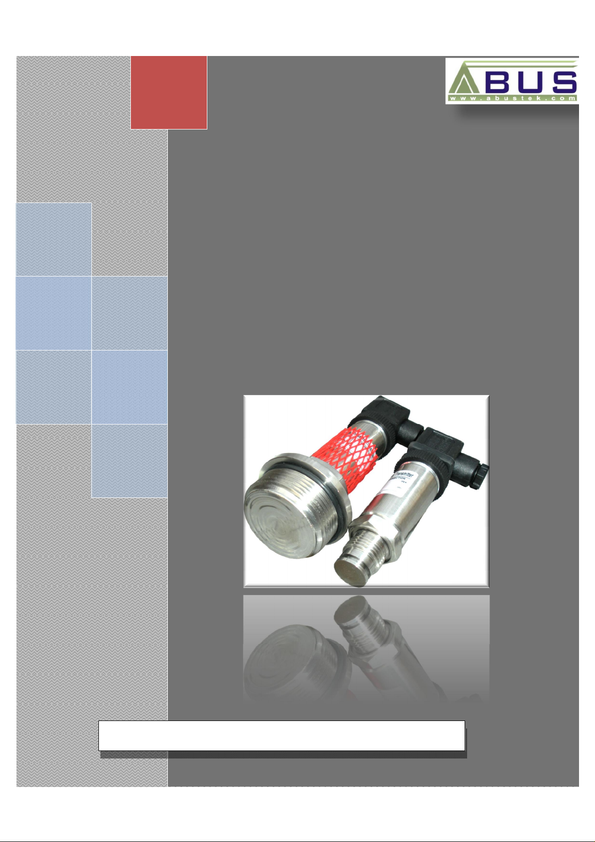
PT
-
FD
Flush Diaphragm
ABUS TECHNOLOGIES INC.
Pressure Transmitter
User Manual
Page 2

WARNING
v This manual should be passed on to the end user.
v The contents of this manual are subject to change without prior notice.
v All rights reserved.
v ABUS gives no warranty of any kind with regard to this manual, including, but not limited to, fitness for a
particular purpose.
v If any question arises or errors are found, or if any information is missing from this manual, please inform
your supplier or inform at info@abustek.com.
v The specifications mentioned in this manual are limited to those for the standard type under the specified
model number break-down and do not necessarily apply for customized instruments.
v Please note that changes in the specifications, construction, or component parts of the instrument may
not immediately be reflected in this manual at the time of change.
v If the customer or any third party is harmed by the use of this product, ABUS assumes no responsibility
for any such harm owing to any defects in the product which were not predictable, or for any indirect
PT-FD
damages.
Although Warning hazards are related to personal injury, and Caution hazards are associated with
equipment or property damage, it must be understood that operation of damaged equipment could, under
certain operational conditions, result in degraded process system performance leading to personal injury or
death. Therefore, comply fully with all Warning and Caution notices.
Information in this manual is intended only to assist our customers in the efficient operation of our
equipment. Use of this manual for any other purpose is specifically prohibited and its contents are not to be
reproduced in full or part without prior approval of Technical Communications Department, ABUS
Technologies
HEALTH AND SAFETY
To ensure that our products are safe and without risk to health, the following points must be noted:
1. The relevant sections of these instructions must be read carefully before proceeding.
2. Warning labels on containers and packages must be observed.
3. Installation, operation, maintenance and servicing must only be carried out by suitably trained personnel
and in accordance with the information given. Any deviation from these instructions will transfer the
complete liability to the user.
4. Normal safety precautions must be taken to avoid the possibility of an accident occurring when operating
in conditions of high pressure and/or temperature.
5. Chemicals must be stored away from heat, protected from temperature extremes and powders kept dry.
Normal safe handling procedures must be used.
6. When disposing of chemicals ensure that no two chemicals are mixed.
Safety advice concerning the use of the equipment described in this manual or any relevant hazard data
sheets (where applicable) may be obtained from the Company address on the back cover, together with
servicing and spares information.
ABUS TECHNOLOGIES INC.
2
Page 3

4. Ordering Details
6
.
PT-FD
CATALOGUE
Contents Page No.
1. Introduction
Applications
2. Presentation
1. Features
2.
3. Dimensions 5
Process Connection According to Pressure Range
5. Connections
Output Characteristics
6. Installation
Recommendation
7. Operation
Example for Usage
8. Maintenance
Troubleshooting
9. Safety Precautions 9
10. Warranty 9
Technical Parameters
4
4
4
4
5
6
6
6
7
7
8
8
8
8
ABUS TECHNOLOGIES INC.
3
Page 4

1. INTRODUCTION
The PT-FD series of transmitters features, a flush diaphragm process connection.
They are specifically designed for the measurement of viscous fluids or media containing
solids that may clog a process connection. Flush diaphragm pressure transmitters are
available in pressure ranges as low as 1500INWC.
The flush diaphragm could be easily flushed or cleaned to remove dirt. The model
offers reliable and accurate pressure measurement of the gases, viscous liquids and
slurries. And for the electrical parts adopt high performance chips, and deal with special
amplified chip, integrated configuration, and smart profile. A wide range of electrical
connection and process connection options are available to meet almost any requirement.
2. PRESENTATION
2.1 Features
1. Improved media compatibility.
2. Excellent resistance to corrosive processes.
3. Compact Design and Rugged construction.
4. Wide range of available process connections and signal outputs.
5. OEM process to fit application of the customers.
6. Resistant to pressure spikes and vibrations.
7. Stainless steel case and wetted parts
8. Can be assembled to diaphragm seals for special applications.
PT-FD
2.2 Technical Parameters
Accuracy: ±0.25%FS (BFSL)
±0.5%FS (limit point calibration)
Ranges: -1 bar… 0 bar…600 bar
Output: 0...5 V, 0...10 V, 0...20 mA, 4...20 mA
Power Supply: 24Vdc (10~36Vdc)
Maximum Pressure: 1.5 x F.S.
Adjustability Zero / Span: ± 10 using potentiometers inside the instrument
Electrical Connections: M12 connector, five Pin bendix connector, Hirschman and Direct
down-lead.
Operating temperature: -40 ~ 125°C (higher range, on request.)
Ambient temperature: -20 ~ +80°C
Process Connection: G1/4, M20 x 1.5, 1/4NPT (Customized On request)
ABUS TECHNOLOGIES INC.
4
Page 5

5
Integral
3. DIMENSIONS
PT-FD
4. ORDERING DETAILS
TYPE DESCRIPTION
Product
Range
Lower Range
Upper Range
Output
Process
Connection
Electrical
Connection
Indicator
(Refer LPI-PT)
Zero and Span
Adjustment
PT-FD PT Series
1 Absolute Pressure 0 ~ 25 bar
2 Gauge Pressure 0 ~ 100 bar
3 Vacuum Pressure -760 ~ 0 mmHG
__ Enter value corresponding to 4mA
Example: PT-FD > 2 >__ > __ > D > 1 > W > LPI-PT > 1
All dimensions in mm
Pressure Transmitter with Flush
Diaphragm
__ Enter value corresponding to 20mA
D
V 0 ~ 10 V
A Others, specify
1
2 G 1”
3 1/2” NPT
4 1” NPT
W
X Thread Screw
Y Bendix Connector
Z Direct Down-lead
LPI-PT
0 W/O Indicator
1 With Internal Z & S
0 W/O
4 ~ 20 mA
G 1/2”
DIN Connector (Hirschman Type)
Loop Powered Indicator
ABUS TECHNOLOGIES INC.
Page 6

6
STANDARD RANGE FOR PT SERIES
PT-FD
S.No.
1 1.00 bar 19 -1 ~ 0.0 bar 7 16.00 bar 25 -1 ~ 9.0 bar
2 1.60 bar 20 -1 ~ 0.6 bar 8 20.00 bar
3 2.50 bar 21 -1 ~ 1.0 bar 9 25.00 bar
4 4.00 bar 22 -1 ~ 1.5 bar 10 40.00 bar VACUUM
5 6.00 bar 23 -1 ~ 3.0 bar 11 60.00 bar 26 -760mm/Hg ~ 0 bar
6 10.00 bar 24 -1 ~ 5.0 bar 12 100.00 bar
Process Connection According to Pressure Range
GAUGE
PRESSURE
S.No. COMPOUND S.No.
CUSTOMIZED RANGES ALSO AVAILABLE
GAUGE
PRESSURE
S.No. COMPOUND
1. Range >10MPa (100 bar) 1. 1 MPa ≤ Range ≤ 10 MPa 1. Range < 1 MPa
2. Sticky and complicated medium 2. If medium is very sticky, and can not 2. If medium is very sticky, and
is allowed keep smoothly flowing. It is unallowed. can not keep smoothly flowing.
It is unallowed
5. CONNECTIONS
Models Lead Color
Output:
1. 0~5V
2. 0.5~4.5V
3. 0~10V
4. DIN43650
Models Lead Color
Output:
1. 4~20mA
2. DIN43650
1. Excitation + Red
2. Signal + Blue
3. Excitation - /
Signal -
1.Excitation + /
Signal +
2. Excitation - /
Signal -
White
Red
Black
ABUS TECHNOLOGIES INC.
Page 7

7
Output Characteristics
PT-FD
ABUS TECHNOLOGIES INC.
Page 8

8
•
•
• Check the span set of Indicating Instrument.
•
6. INSTALLATION
Recommendation
1. Please confirm the configuration for Pressure Transmitter i.e. 2- wire, 3-wire and accordingly follow the
wiring procedure. Ensure that the excitation voltage is supplied to the correct points and is with in the
specified limits for that particular configuration as mentioned in the table above.
2. When installed, ensure that the transmitter is not subjected to the excessive sources, and it should be
considered before installing the Transmitter. Use suitable diaphragm if needed.
3. Process connection must be properly sealed with material compatible with the process liquid / gas.
4. When installing transmitter with diaphragm, seals / process connector should be tightened not the
transmitter, otherwise transmitter calibration may get affected.
7. OPERATION
Example for Usage
PT-FD
8. MAINTENANCE
Troubleshooting
S. No. SPECIFICATIONS ELIMINATE
1 No output
2 No variation in output
Output not holding at
3
constant input pressure.
ABUS TECHNOLOGIES INC.
Check the wiring configuration.
• Check the input power supply.
Check for leakage at pressure port / point.
Check for leakage pressure point.
• Check for the connections ensure they are properly
tightened.
Page 9

9. SAFETY PRECAUTIONS
1. The unit should be powered for 15 minutes before use.
2. Use in ambient temperature of 0-60˚C.
3. Avoid vibrations, shock, excessive dust, corrosive chemical materials or gaseous
environment.
4. Input wire should not be too long. If measured signal have to be far away from the unit,
please use 2-core shielded cable.
5. Use this instrument in the scope of its specifications, otherwise fire or malfunctions may
result.
6. Contact of the instrument, with organic solvents or oils should be avoided.
7. Do not turn on the power supply until all of the wiring is completed. Otherwise electrical
PT-FD
shock, fire or malfunction may result.
8. Do not disassemble, repair or modify the instrument.
9. All connections should be tightened properly.
10. Power supply should be constant, should not be fluctuating.
10. WARRANTY
ABUS provides the original purchaser of this instrument a one (1) year warranty against
defects in material and workmanship under the following terms:
• The one year warranty begins on the day of shipment as stated on the sales bill.
• During the warranty period all costs of material and labor will be free of charge provided
that the instrument does not show any evidence of misuse.
• For maintenance, return the instrument with a copy of the sales bill to our factory.
• All transportation and insurance costs should be covered by the owner of the equipment.
• Should any sign of electrical or mechanical shock, abuse, bad handling or misuse be
evident the warranty voids and maintenance costs will be charged.
REV 01
Added Process Connection Data in Page 6
•
Changed Front Page Picture
•
ABUS TECHNOLOGIES INC.
www.abustek.com, E-Mail: info@abustek.com
ABUS TECHNOLOGIES INC.
9
 Loading...