

Page 1

PPIC32020 / PPIC32520 / PPIC34520 /
PPIC35520 / PPIC36520
User guide
You can find important information and F AQs about this and other
products online at:
www.abus-smartvest.com
Version 1.4
Firmware: 1.1.1.30 (PPIC32020, PPIC32520, PPIC34520)
Firmware: 1.1.1.22 (PPIC35520)
Firmware: 1.1.0.32 (PPIC36520)
English translation of the original German instruction manual.
Retain for future reference.
Page 2
English
Introduction
Dear Customer,
Thank you for purchasing this product.
ABUS Security-Center hereby declares that the PPIC32020, PPIC32520, PPIC34520 and
PPIC35520 cameras co mp ly with R ED Dire ctiv e 2014/5 3/EU. Additio nally, these dev ices co mpl y
with the requirements of the following EU directives: EMC Directive 2014/30/EU and the RoHS
Directive 2011/65/EU. The full text of the EU Declaration of Conformity may be found a t:
www.abus.com/product/PPIC32020
www.abus.com/product/PPIC32520
www.abus.com/product/PPIC34520
www.abus.com/product/PPIC35520
www.abus.com/product/PPIC36520
To ensure this remains the case, an d to guarantee safe operation, you the user must observe the
instructions in this user guide.
Read the entire user guide c arefully before starting operation of the product, and pay attention to all
operating instructions and safety information.
All company names and product descriptions are trademarks of the corresponding owner. All
rights reserved.
If you have any questions, please contact your local specialist dealer or visit our website a t
http://www.abus-smartvest.com
Data storage is subject to national data privacy guidelines.
Warning as required by Section 201 StGB (Germa n Criminal Code):
Whosoever unlawfully makes an audio recording of the privately spoken words of another, and uses
or makes a recording thus produced accessible to a third party, shall be liable to imprisonment or a
fine.
Whosoever unlawfully overhears with an eavesdropping device the privately spoken words of
another not intended for his attention, or publicly communicates, verbatim or the essential content
of, the privately spoken words of another, recorded or overheard, shall incur the same penalty.
Disclaimer
This user guide has bee n p r oduced with the greatest o f c are. Should you discover any omissions or
inaccuracies, please contact us in writing at the address provided above.
ABUS Security-Center GmbH does not accept any liability for technical and typographical errors, and
reserves the right to m ake changes to the product and user g uides at any time and without prior
warning.
ABUS Security-Center GmbH is n ot liab le or res p ons i ble f or direct or indirect d amage resulting f r om
the equipment, perform ance and use of this pr oduct. No g uarantee is made for t he contents of this
document.
2
Page 3

English
Contents
1. Scope of delivery ................................................................................................................................. 5
2. Description of the hardware ................................................................................................................. 6
2.1. PPIC32020 ................................................................................................................................... 6
2.2. PPIC32520 ................................................................................................................................... 6
2.3. PPIC34520 ................................................................................................................................... 7
2.4. PPIC35520 ................................................................................................................................... 8
2.5. PPIC36520 ................................................................................................................................... 9
3. Description of hardware functions ..................................................................................................... 10
3.1. Status LEDs ............................................................................................................................... 10
3.2. Factory settings/reset ................................................................................................................. 11
3.3. White light LED .......................................................................................................................... 11
3.4. Call button (PPIC35520 only) ..................................................................................................... 11
3.5. RFID Reader (PPIC35520 only)................................................................................................. 12
3.6. Micro USB connection ................................................................................................................ 12
4. Mounting/installation .......................................................................................................................... 13
4.1. PPIC32020 ................................................................................................................................. 13
4.2. PPIC32520 ................................................................................................................................. 13
4.3. PPIC34520 ................................................................................................................................. 14
4.4. PPIC35520 ................................................................................................................................. 15
4.4.1. Mounting plate ...................................................................................................................... 15
4.4.2. Preparation ........................................................................................................................... 15
4.4.3. Cabling ................................................................................................................................. 16
4.4.4. Adjustable lens ..................................................................................................................... 18
4.4.5. Final installation .................................................................................................................... 18
4.5. PPIC36520 ................................................................................................................................. 19
5. App2Cam Plus: First access ............................................................................................................. 21
5.1. Download app ............................................................................................................................ 21
5.2. Setting up the camera ................................................................................................................ 21
5.2.1. Wi-Fi set-up (Android) .......................................................................................................... 21
5.2.2. Wi-Fi set-up (iOS) ................................................................................................................. 22
5.2.3. LAN set-up/Adding a camera that is already set-up ............................................................ 23
6. App2Cam Plus: Compatibility ............................................................................................................ 23
7. App2Cam Plus: Overview .................................................................................................................. 23
7.1. Menu bar .................................................................................................................................... 24
7.2. Camera bar ................................................................................................................................ 25
7.3. Info/app settings ......................................................................................................................... 25
8. App2Cam Plus: Live view .................................................................................................................. 26
8.1. Live cast functions ...................................................................................................................... 26
8.2. Pan/tilt function ........................................................................................................................... 27
8.3. Active/inactive function ............................................................................................................... 27
8.4. Automatic adjustment of video quality ....................................................................................... 27
8.5. Stream indicators ....................................................................................................................... 28
3
Page 4

English
9. App2Cam Plus: Event list/playback ................................................................................................... 29
9.1. Event list ..................................................................................................................................... 29
9.1.1. Event list functions ............................................................................................................... 29
9.1.2. Mode (iOS only) ................................................................................................................... 29
9.2. Playback ..................................................................................................................................... 30
9.2.1. Playback functions ............................................................................................................... 30
10. Camera settings .............................................................................................................................. 31
10.1. Login details ............................................................................................................................. 31
10.2. Email notification ...................................................................................................................... 31
10.3. Open advanced settings .......................................................................................................... 31
10.4. Automatic log-in ....................................................................................................................... 32
11. Advanced camera settings .............................................................................................................. 32
11.1. Security settings ....................................................................................................................... 32
11.2. Video settings ........................................................................................................................... 33
11.3. Component settings (PPIC35520 only) .................................................................................... 33
11.4. Sound settings (PPIC35520 / PPIC36520 only) ...................................................................... 34
11.5. Relay settings (PPIC35520 only) ............................................................................................. 34
11.6. Network settings ....................................................................................................................... 34
11.7. Motion detection settings ......................................................................................................... 35
11.8. Notification settings .................................................................................................................. 35
11.9. Storage settings ....................................................................................................................... 35
11.10. Device settings ....................................................................................................................... 36
12. Updating firmware: .......................................................................................................................... 37
12.1. Update via server ..................................................................................................................... 37
12.2. Update manually ...................................................................................................................... 37
12.3. Current firmware version .......................................................................................................... 37
4
Page 5

English
1. Scope of delivery
PPIC32020
• Wi-Fi pan/tilt camera
• Power supply unit, 5 V DC/1.5 (EU, UK)
• Network cable 1 m
• Antenna
• Ceiling bracket
• Installation material
• Quick guide
PPIC34520
• Wi-Fi outdoor camera
• Power supply unit, 5 V DC/1.5 (EU, UK)
• Micro USB – RJ45 adapter
• Antenna
• Wall bracket
• Installation material
• Quick guide
PPIC32520
• Wi-Fi pan/tilt outdoor camera
• Power supply unit, 5 V DC/1.5 (EU, UK)
• Network cable 1 m
• Antenna
• Wall bracket
• Installation material
• RJ45 coupling
• Quick guide
PPIC35520
• Wi-Fi video intercom system
• Power supply unit, 12 V DC/1 (EU, UK)
• Power cable
• Network cable
• Network cable 1 m
• Triangle screwdriver
• Name plate
• Installation material
• Quick guide
PPIC36520
• Wi-Fi outdoor camera
• Antenna
• Wall bracket (incl. power supply unit)
• Drilling template
• Installation material
• Quick guide
5
Page 6
English
2. Description of the hardware
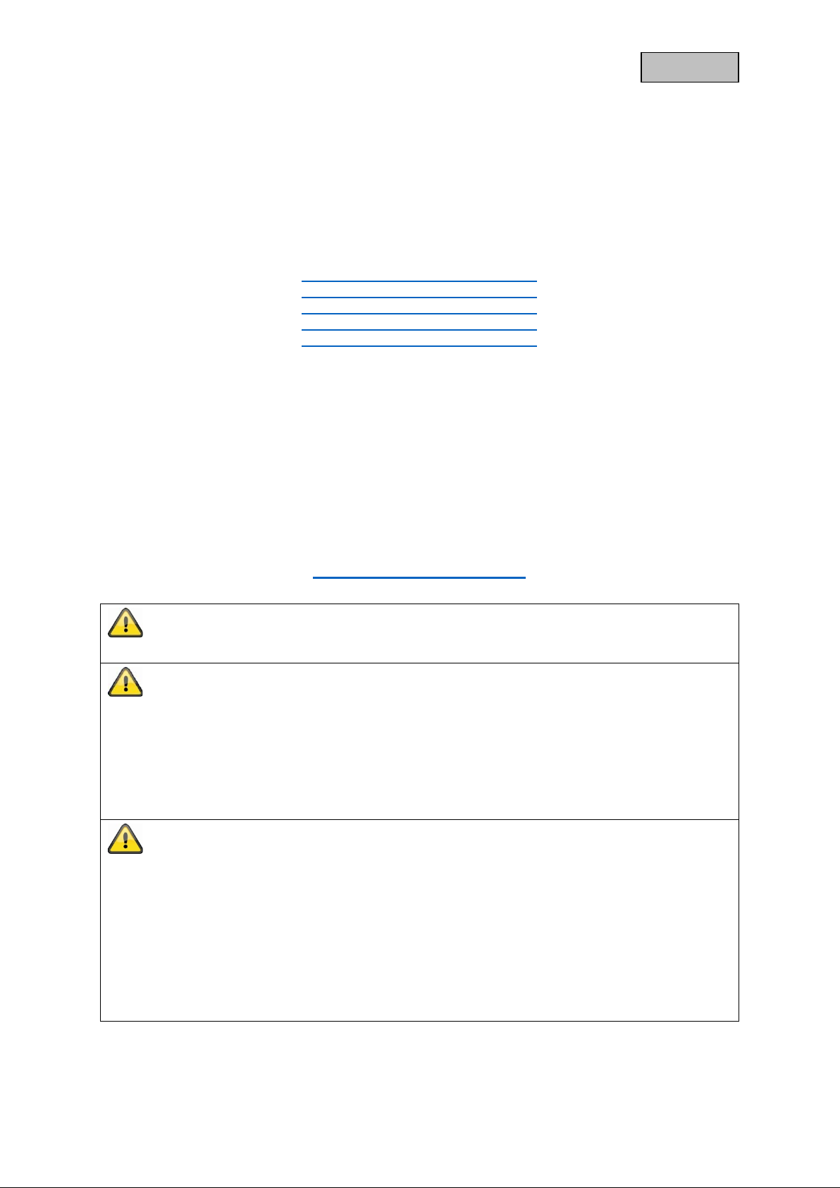
2.1. PPIC32020
1 IR LEDs 2 Photo sensor
3 Lens 4 Microphone
5 Loudspeaker 6 LAN interface
7 Reset button 8 MicroSD card slot (max. 128 GB)
9 Power/Status LED 10 Power supply (5 V DC)
11 Antenna connection (RP-SMA)
2.2. PPIC32520
1 Internal MicroSD card slot 2 Internal reset button
3 Antenna connection (RP-SMA) 4 IR LEDs
5 Power/Status LED 6 Lens
7 Photo sensor 8 RJ45 (male) for LAN connection
9 Power supply (5 V DC) 10 MicroSD card slot (max. 128 GB)
11 Reset button
6
Page 7

English
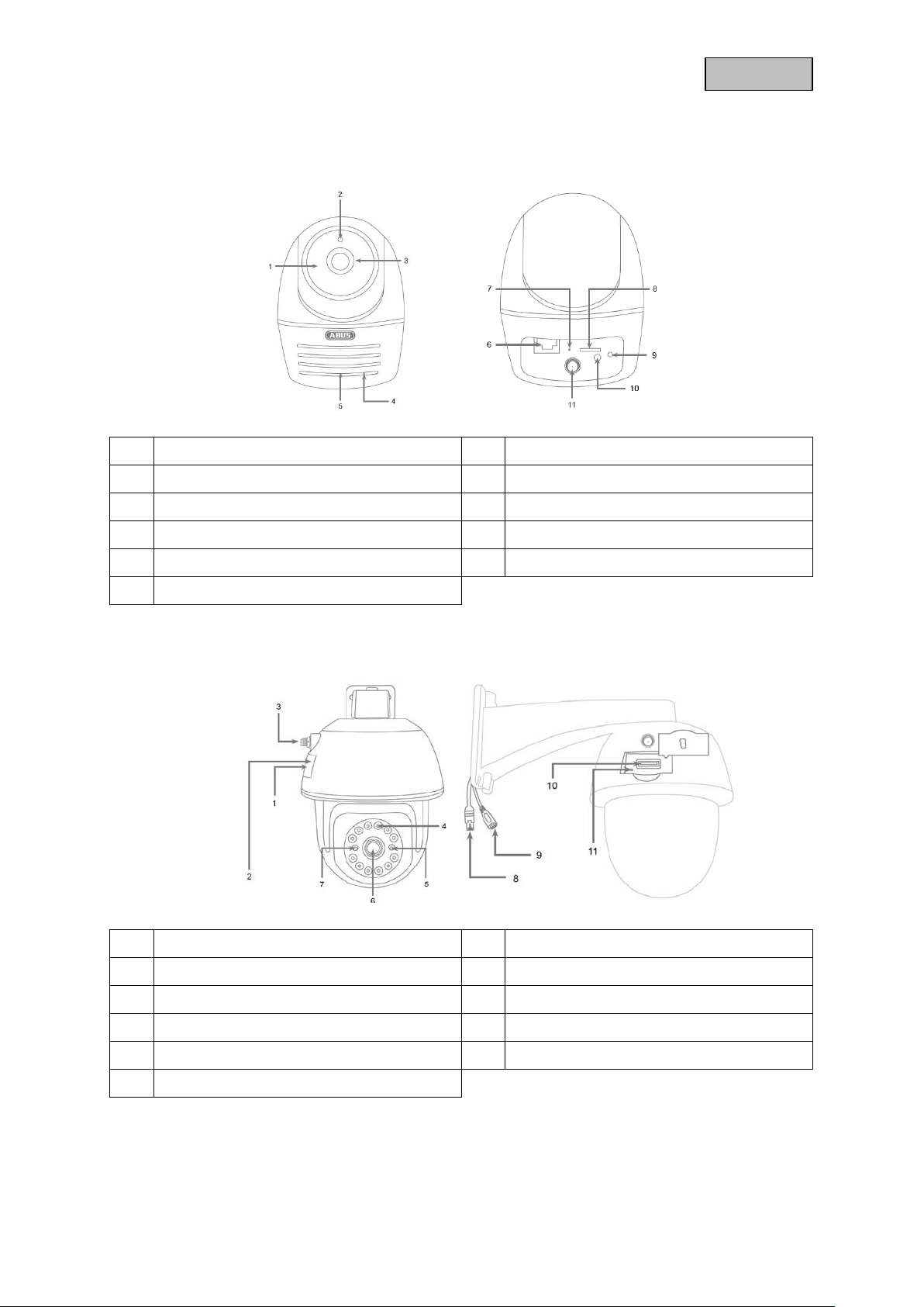
2.3. PPIC34520
1 Lens 2 Photo sensor
3 IR LEDs 4 Power and status LED
5 PIR sensor 6 Microphone
7 Antenna connection (RP-SMA) 8 Reset button
9 Internal MicroSD card slot
(max.128 GB)
11 Power supply (5 V DC)
10 Internal
micro USB interface
for LAN connection
7
Page 8
English
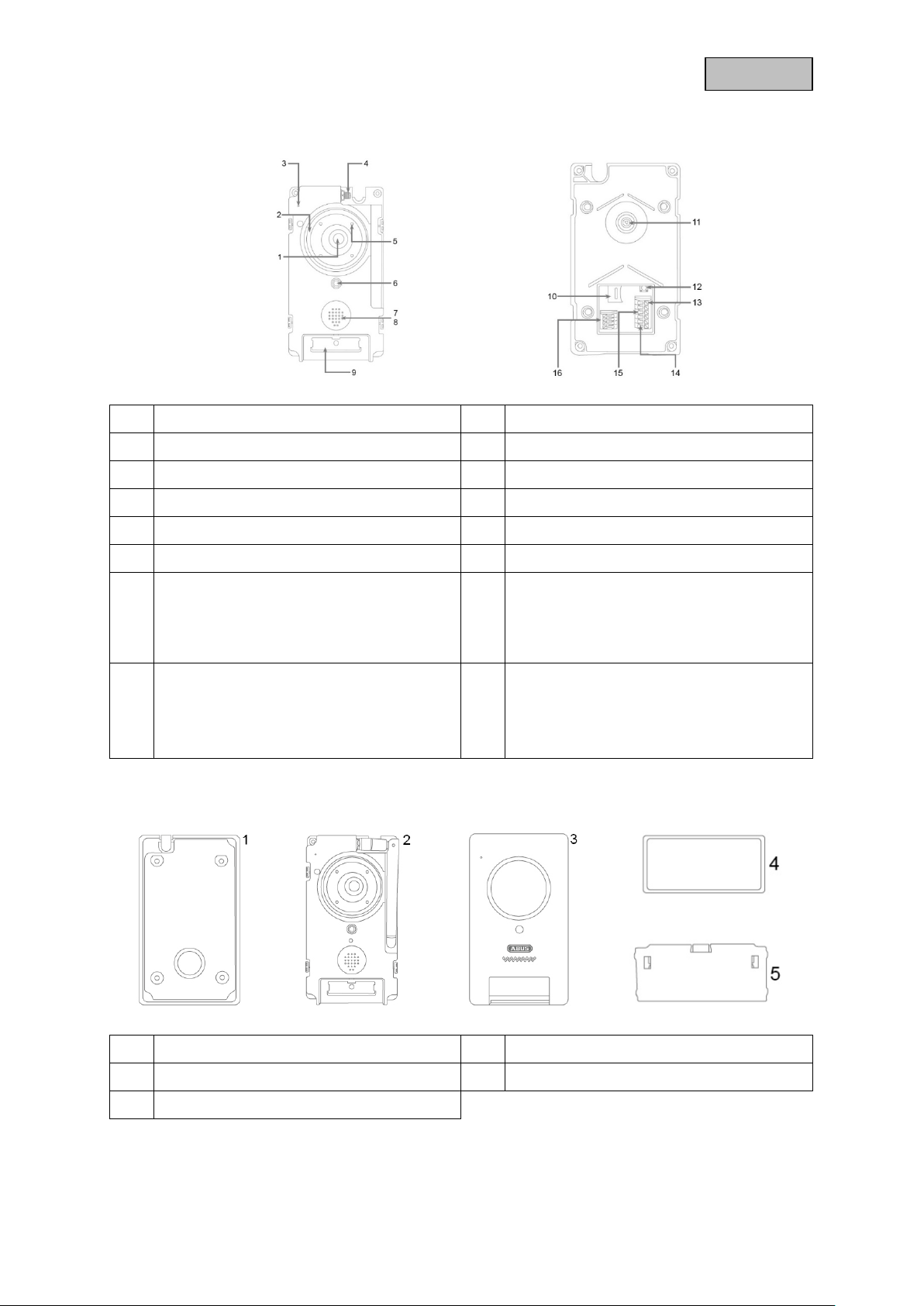
2.4. PPIC35520
1 Lens 2 White light LED ring
3 Microphone 4 Antenna connection (RP-SMA)
5 IR LEDs 6 Photo sensor
7 Loudspeaker 8 RFID reader
9 Call button 10 MicroSD card slot (max. 128 GB)
11 Adjustable lens (V: 7.5%, H: 2.5%) 12 Reset button
13 B2/B1 connector block:
Potential-free rela y for c onnec tion f or, e.g.
door opener.
Maximum input 2A / 24V AC/DC
15 V-/V+ connection block:
Connection for power supply.
AC – Alternating Current: 9–36 V
DC – Direct Current: 12–48 V
Individual intercom components
14 C2/C1 connector block:
Potential-free relay for connection for an
external doorbell.
Maximum input 2A / 24V AC/DC
16 TD-/TD+/RD-/RD+ connector block
LAN interface connection
1 Mounting plate 2 Door station
3 Cover 4 Call button cover
5 Call button pressure plate
8
Page 9
English
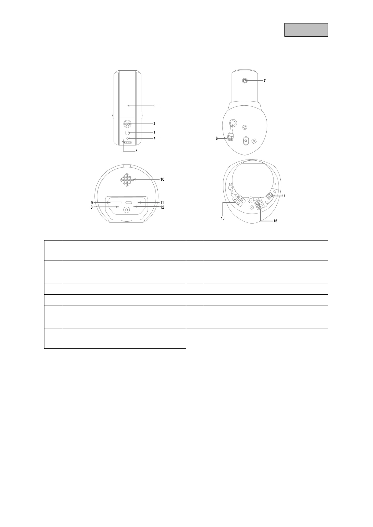
2.5. PPIC36520
1 White light LED
IR LEDs
3 PIR sensor 4 Photo sensor
5 Microphone 6 Camera connection cable
7 Antenna connection (RP-SMA) 8 Status LED
9 MicroSD card slot (max. 128 GB) 10 Loudspeaker
11 Reset button 12 Power LED
13 Power supply (90–260 V AC) 14 Camera connector block
15 Connector block 1/2/3/6
LAN interface connection
2 Lens
9
Page 10

English
3. Description of hardware functions
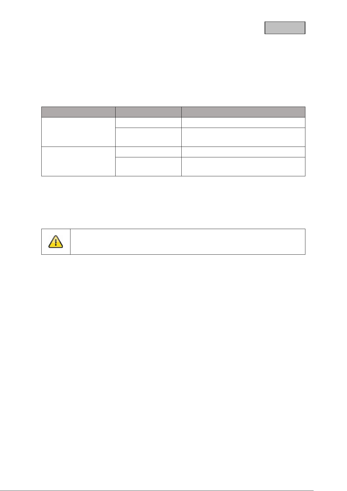
3.1. Status LEDs
PPIC32020
LED Status Description
Power and status
LED
PPIC32520
LED Status Description
Power and status
LED
Lights up green
Flashes green
Flashes green
(2 x short & 1 x long)
Off
Lights up red
Flashes red
Flashes red
(2 x short & 1 x long)
Off
Camera connected to power
Camera connected to network
Camera set to the factory settings
Camera firmware is being updated
Camera connected to power
Camera sends its own access point out
Camera has no power supply
Camera not connected to any network
Camera connected to power
Camera connected to network
Camera set to the factory settings
Camera firmware is being updated
Camera connected to power
Camera sends its own access point out
Camera has no power supply
Camera not connected to any network
PPIC34520 / PPIC35520
LED Status Description
Power LED
Lights up green Camera connected to network
LED status
Flashes green
(2 x short & 1 x long)
Lights up red Camera connected to power
Flashes red
Off Camera has no power supply
Off Camera not connected to any network
Camera set to the factory settings
Camera firmware is being updated
Camera sends its own access point out
10
Page 11

English
Connection to intercom established / call
PPIC36520
LED Status Description
Lights up white Camera connected to power
Camera set to the factory
Power LED
Flashes white
Off Camera has no power supply
Lights up blue Camera connected to network
settings
Camera firmware is being
updated
Flashes blue
LED status
(2 x short & 1 x long)
Off
Camera sends its own access
point out
Camera not connected to any
network
3.2. Factory settings/reset
To reset the camer a to its factor y settings, pres s and hold th e reset button f or five s econds while the
camera is operating.
3.3. White light LED
PPIC35520
LED Status Description
White light LED
ring
PPIC36520
On
Flashing Call button has been pressed, call waiting
Off No active connection
accepted
LED Status Description
White light LED
On Motion detected, switched on manually
Off No motion detected, switched off manually
3.4. Call button (PPIC35520 only)
Pressing the call button triggers the following response from the intercom system:
• Call triggered
• Relay for external doorbell (C2/C1) is triggered
• The white LED ring begins to flash
11
Page 12
English
3.5. RFID Reader (PPIC35520 only)
You can program and use the ABUS AZ5502 pr ox im it y c hips in th e i nter c om with the help of the builtin RFID reader. The RFID reader is located behind the loudspeaker, just above the call button.
To do this, enable programm ing in the intercom ’s advanced settings and hold th e chip in front of the
intercom until you hear a beeping sound and the app displays the next step.
You can perform different actions by using the chip in different ways.
Response
Use Response Action
Hold the chip just in front
of the RFID reader for
one second
Hold the chip in front of
the RFID reader until
there is a response.
Beeps 1x Relay (B2/B1) triggered
Beeps 3x
Beeps 2x -
Beeps 3x
Chip could not be read
Chip not recognised
Chip could not be read
Chip not recognised
3.6. Micro USB connection
PPIC34520
With the enclosed n et work adapter cable, the PPIC34520 can be con nect e d to a network with a cable
via the micro USB connection under the cover at the back.
Important!
The weather resis tance of the cam era is invalidat ed when a perm anent c onnection to a
network via the network adapter cable and the micro USB connection is used.
PPIC36520
The PPIC36520 can be supplied with power at short notice b y connecting to a power bank or sim ilar
via the micro USB c on nec ti on o n t he und er s ide. T her e b y ensur i ng the Wi-Fi connection can be t este d
at the desired installation location.
12
Page 13

English
4. Mounting/installation
IMPORTANT!
The camera must be disconnected from the power supply during installation.
4.1. PPIC32020
Position the mount wher e you inten d to install th e camera. Mar k up and dr ill the requ ired holes. N ext,
use the screw anchors and screws provided to fasten the mount in place.
Important!
Make sure the alignment i s correct. The 'LOCK' text must point in the dir ection of the
scene to be monitored.
Use the small screws provided to fasten the base plate to the camera.
Position the camera with the base plate on the mount in such a way that the arrow on the base plate is
aligned with 'UNLOCK' on t he mount. Next, fix the camera in place by turni ng the camera c lockwise.
The arrow must be aligned with 'LOCK'.
4.2. PPIC32520
If the camera is being installed on a roughcast wall, use the EVA foam provided and glue it to the back
of the mount.
First of all, disconnec t the mount from the camera using th e Allen key provided. Position the mount
where you intend to insta ll the cam era. Mark up and drill the re quired holes. Insert the s crew anchor s
provided.
Reconnect the cam era to the mount and feed the cab le through the m ount. Next, screw th e camera
and mount to the wall.
13
Page 14

English
Cabling tips
If you do not have the option of feeding the cable through the wall, the following alternatives are
available:
1. Cable duct:
Feed the cable downwards and out from the mount. Use a cable duct (width at least 40 mm, depth
at least 30 mm) to protect the laid cable.
2. Surface-mounted box:
Use a surface-mounted box (width and height at least 105 m m , depth at least 3 5 m m) and dril l a
hole into the box's cover s o that the network cable and po wer cable can be f ed into the surf acemounted box. Next, install the camera and mount on the cover of the surface-mounted box. Install
the surface-mounted box in the desired installation location and screw the cover in place together
with the camera.
4.3. PPIC34520
Position the mount wher e you inten d to install th e camera. Mar k up and dr ill the requ ired holes. N ext,
use the screw anchors and screws provided to fasten the mount in place.
Next, install the cam era on the m ount by screw ing the c amer a clock wise on to the thread. As soon as
the camera is fully screwed into position, lock the camera further into place by tightening the wing nuts
from underneath.
For alignment purposes, loosen the wing screw at the side and align the camera in the desired position.
Next, lock the camera into place once more by tightening the wing screw.
14
Page 15
English
4.4. PPIC35520
This intercom is particularly well suited to retrofitting. It can usually be wired using the existing cabling
if the existing doorbell is replaced. Use an ammeter to check whether there is sufficient voltage in the
existing cables. Otherwise, the power supply will have to be installed separately. You will find further
details and illustrations of the exact wiring below.
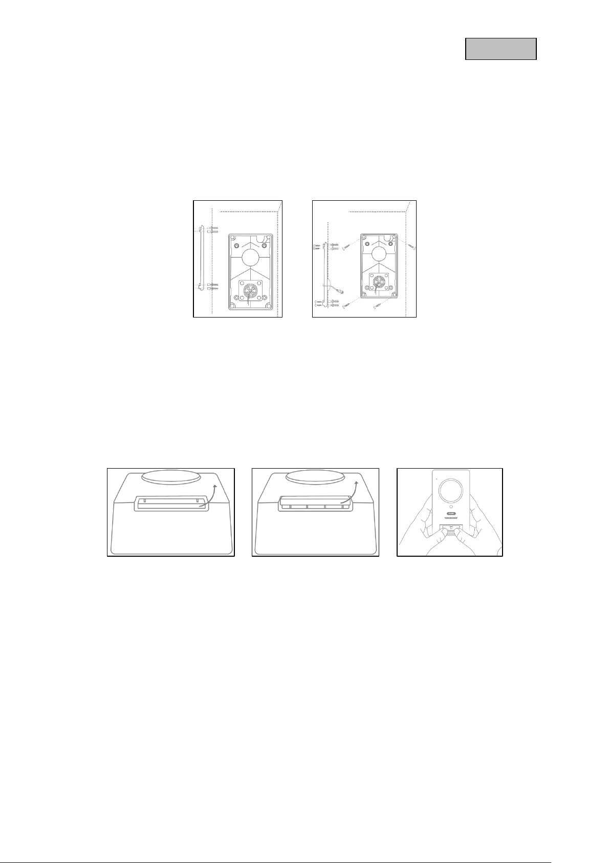
4.4.1. Mounting plate
First, separate the mounting plate from the door station. Place the mounting plate in the desired
installation location, and mark and drill the required holes. For the best field of view, we recommend an
installation height of at least 1.3 m (4.25 ft). Inser t the scr ew anchors provid ed. Next, run t he existing
or replacement cabli ng through the ring ope ning on the m ounting plate. W e recommend you use the
rubber ring provided for better protection against water and other fluids. Perforate the ring at the
specified points in order to run the c able t hrou gh, and place the r ing in the r i ng-shaped opening in th e
mounting panel. Then use the screws provided to fix the mounting plate in place.
4.4.2. Preparation
When shipped from the factory, the door stat ion is connecte d to the call button cover, t he call button
pressure plate and the co ver. T o continu e install ation, f irst rem ove the ca ll butto n cover , then th e call
button pressure plate. To remove the cover, exert a little pressure on the call button area, which should
now be easily accessible, and pull the cover upwards and away from the door station
15
Page 16

English
4.4.3. Cabling
Should you wish to use the intercom with the accessories provided, connect the power supply by
connecting the two wires from the m ains power c able to the connec tor block . Connect t he red wire to
DC+ and the black wire to DC- by pr essing down the relevant pin and inserting the cable. Finall y,
connect the power supply unit provided to the power supply cable.
If you wish to use cabling from an existing doorbell, or if you want to connect the intercom to an
additional actuator (e. g. a d oor opener) or to an LA N n et work, use the wiring di agr am s belo w t o g ui de
you.
Establishing a power supply using existing cabling
In order to supply power v i a exis tin g cabling, you will need t o ha ve at le as t on e p air of wires available.
These might come from an additional power supply unit or from the bell transformer (1). Use an
ammeter to check whether there is sufficient voltage available, and connect the wires to the connection
block V-/V+. When working with DC voltage, please observe the correct polarity.
Please note that the i ntercom requires a p ower supply of 4.8 W to operate reliably. Acc ordingly, the
existing power suppl y unit or bell transf ormer that are being used must be able to deliver a c ertain
current (Ampere). T his is independent from the type of voltage ( alternating current or direct current).
Different voltage thresholds can be found in a table with the required current.
Voltage
Current
9 V 12 V 36 V 48 V
0.53 A 0.4 A 0.13 A 0.1 A
16
Page 17

English
Connecting an external doorbell and/or a n actuator (e.g. door opener)
To connect an existing doorbell or actuator via existing cabling you will need to have at least two pairs
of wires available. These might come from an additional power supply unit or from the bell transformer
(1). Use an ammeter to check whether there is sufficient voltage for the power supply.
Important!
Be careful not to exceed the maximum voltage for the relay
Connect the first pa ir of wires to the c onnector block V-/V +. When working with DC voltage, please
observe the correct polarity.
Connect one of the second pair of wires to t he d oor b el l and/ or ac t uator and the ot her to t he c o nnec tor
block (C1/B1). Connect a separate wire to the doorbell and/or actuator and the connector block (C2/B2).
Safety notice on use of a door opener
The relay (B2/B1) is a s imple potential-free re lay. It can be triggere d manually by pulling
off the intercom and conne cting the wires manuall y. W e therefore advise you not to use
this relay for a door opener connected to the outside doors of your home. Should you still
wish to connect it, please ensure that your outside doors are locked whenever you leave
the house.
Connecting to an LAN network
In order to connect the intercom with a network cable, use either the network connector cable provided,
an existing cable, or a nother free network cable. Con nect the cable to the network connector block
according to the colour-coding below.
Connector block Colour – network connection cable Colour – Cat 5e network cable
TD- Green Green
TD+ Red Green / white
RD- Black Orange
RD+ Orange Orange / white
17
Page 18

English
4.4.4. Adjustable lens
The door station’s lens can be adjusted on the back by up to 7.5% vertically and 2.5% horizontally. To
adjust the lens, loosen th e screw using the triangle screwdriver provide d. We recomm end you first
connect your intercom to the App2Cam Plus on your network before final installation in order to ensure
it is perfectly pos itioned . F ix the pos ition of the lens b y tig htenin g the scr ew on t he re ar of t he brack et
using the triangle screwdriv er.
4.4.5. Final installation
To complete install ation, unscrew the aerial from the door station and mount the door s tation on the
mounting plate using the triangle screwdriver and the four triangular screws provided. Screw the aerial
back on to the door station and affix the cover to the door station. Finally, replace the call button
pressure plate and the doorbell cover.
18
Page 19

English
4.5. PPIC36520
IMPORTANT!
Electrical wires must be disconnected from the power supply during installation. Therefore,
the power should firstl y be turned off and then tested t hat there is no v oltage with a circuit
tester. The installation of the device involves works on the mains power supply. This is why
it must be carried out by a specialist according to national installation regulations and
connection requirements.
Mark the required dri ll holes with the su pplied drilling tem plate and drill the hol es. Secure the m ount
using the screws and wall plugs included. Feed the existing conductor through the respective holes by
perforating the rubber s ealing. Connect th e live conduc tor and the neutral cond uctor with the ex isting
lustre terminal. For a simplified installation, take the lustre terminal out from its bracket.
L – live conductor (mostly black or brown)
N – neutral conductor (mostly blue)
Connect the camera c onnec tion cab le to t he c amera connector block. Af ter, ins ert t he camera into the
bracket. Mount the camera onto the bracket by using the Allen key provided. Mount the antenna to the
camera. Turn on the power to the camera. The camera will be ready for further set-up when the power
LED light stays lit and the status LED flashes quickly twice and then once for longer.
19
Page 20

English
Connecting to an LAN network
Connector block Colour – Cat 5e network cable
1 Green / white
2 Green
3 Orange / white
6 Orange
20
Page 21

English
5. App2Cam Plus: First access
5.1. Download app
Download the ‘App2Cam Plus’ app from the Google Play Store or Apple App Store
before your initial access.
5.2. Setting up the camera
Connect the camera to the power to begin set-up. If you would like to connect the camera to your home
network (router) using the network cable, attach the network cable to the camera before connecting the
camera to the power.
The camera will be ready for set-up after approx. 60 seconds.
5.2.1. Wi-Fi set-up (Android)
Open the app and select option 1 to set up the camera on your Wi-Fi network.
The app will automatically search for the camera's Wi-Fi access point. If multiple cameras are available
at the same tim e during set-up, you will be shown a list of cam eras. Select the r equired camera an d
press the arrow key to continue with installation.
Before connecting t he camera t o the W i-Fi, the app prom pts you to chang e the secur ity code on the
camera, which is required to integrate the camera. Enter a security code and confirm it.
Note
This security code should consist of at least eight charact ers and meet at least two or
three of the following criteria:
• Uppercase letters (A–Z)
Select your home network Wi-Fi from the list of Wi-Fi networks, then enter the Wi-Fi password for your
home network. Press 'OK' to set up the connection.
The camera tak es approx. 90 seconds t o set up a connecti on with the W i-Fi network. If the cam era
does not connect despite this set-up, r eset the cam era using the Reset button and rep eat the above
steps.
• Lowercase letters (a–z)
• Numbers (0–9)
Special characters ar e not allowed. The camera' s s tandar d sec ur ity code '123456' is not
permitted.
21
Page 22

English
5.2.2. Wi-Fi set-up (iOS)
Before opening the app, go to your device's network settings and connect to your camera's Wi-Fi access
point. This will have the name 'HD-XXXXXX'. The password for the camera's Wi-Fi access point:
'12345678'.
Once the connection is set up, open th e app and select option 1 to set up th e camera on your Wi-Fi
network.
Before connecting t he camera t o the W i-Fi, the app prom pts you to chang e the secur ity code on the
camera, which is required to integrate the camera. Enter a security code and confirm it.
Note
This security code should consist of at least eight character s and meet at least two or
three of the following criteria:
• Uppercase letters (A–Z)
Select your home network Wi-Fi from the list of Wi-Fi networks, then enter the Wi-Fi password for your
home network. Press 'OK' to set up the connection.
The camera tak es approx. 90 seconds t o set up a connecti on with the W i-Fi network. If the cam era
does not connect des pite this set-up , reset the cam era using the Res et button and r epeat the abo ve
steps.
• Lowercase letters (a–z)
• Numbers (0–9)
Special characters ar e not allowed. The camera' s s tandar d sec ur ity code '123456' is not
permitted.
22
Page 23

English
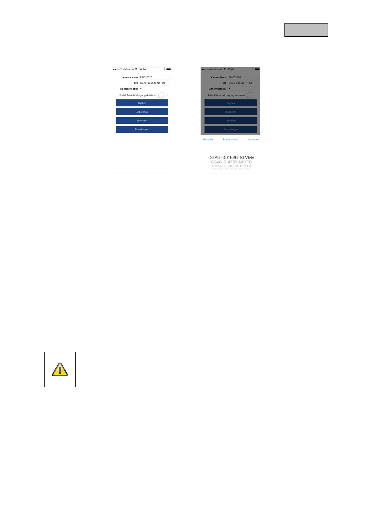
5.2.3. LAN set-up/Adding a camera that is already set-up
To set up a cam era on a LAN network , use the network cable to connect the camera to your home
network (router) before connecting the camera to the power.
Open the app and select option 2 to set up the camera on your LAN network.
Enter a name for your camera.
Use the 'Search' button to search for the camera on the network or enter the camera's DID manually.
You now need to enter the camera's standard security code, '123456'. If the camera has already been
set up, enter the security code previously assigned to the camera.
Press the 'Save' button to add the camera.
Note
If the camera has been a dded with the standar d security code, ' 123456', this ha s to be
changed to the camera's live cast the first time it is accessed.
Note
If the camera has already been set up via another smartphone or user, select this method
to add cameras that are already set up.
6. App2Cam Plus: Compatibility
The App2Cam Plus is compatible with the following devices:
• PPIC32020 / PPIC32520 / PPIC34520
• PPIC35520
• TVAC19000A-B / TVAC19100A-B
Note
Please note that som e of the func tions explained or demons trated in these instr uctions
may not be compatible wit h older generation cam eras, or the cam era functions may be
different due to differences in the hardware.
7. App2Cam Plus: Overview
Note
The screenshots and icons shown here are from the iOS app.
23
Page 24

English
The text, layout or f unctions m ay differ slightly from the Android app. If this is the cas e,
this will be flagged up in the respective items or as an addendum – (iOS only) or (Android
only).
In the overview, you can click on one of the preview images to open the camera's live cast.
There are other functions you can use in the menu bar, camera bar and in the info/app setting.
7.1. Menu bar
Set up new camera/Add camera
Enable/disable camera bar
Start new attempt to connect cameras not yet connected
Open info/app settings
24
Page 25

English
7.2. Camera bar
Open camera settings
Delete camera
Open event list
7.3. Info/app settings
PIN settings
About
App PIN
Menu in which you can assign an app pin. If enabled and assigned, this will
be requested every time you open the app.
About
This section provides information about the current version of the app, data
protection guidelines and API version.
Instructions
User handbook
Video acceleration
(Android only)
You can call up the produc t page for the selected c amera here. You can
download the instructions from the download sector.
Enable/disable hardware decoding
Hardware decoding is available for use on Android. Some Android devices
have special hardware features which optimise the decoding of video
streams.
On older products or older Andro id d ev ices , this may impact negatively on
performance.
25
Page 26

English
8. App2Cam Plus: Live view
In the live cast, a variety of different functions are available to you, depending on the model of camera.
A full screen view, without functions, is shown in landscape mode.
8.1. Live cast functions
Create capture
Enable/disable audio output
Start manual recording
Open pan/tilt menu
Activate two-way communication
PPIC35520 only:
stop/play picture
PPIC36520 only:
Switch on light manually, switch on auto mode, switch off light manually
PPIC36520 only:
Enable/disarm siren
26
Page 27

English
8.2. Pan/tilt function
For pan/tilt cameras, you can either use a 'swipe' com mand to control the camera or long-press and
release one point to bring the camera to that point.
Pan/tilt menu
Save or retrieve point 1 / starting point
Save or call up point 2
Save or retrieve point 3
Calibration Camera calibrates itself once
Cancel Cancel
8.3. Active/inactive function
Click the 'Arm' or 'Disarm ' button to activate or deacti vate the camera. You always h ave to enter the
admin password.
Camera is switched on
In its 'armed' state, th e camera records when m otion is detected and sends
notifications (push)
Camera is switched off
In its 'disarmed' state, the camera takes no further action when motion is
detected.
8.4. Automatic adjustment of video quality
If the quality of the con nection to your cam era gets worse and t he video quality is set too hi gh for the
existing connection, the a p p w ill s ugg es t automatically that the video qua lity be adjusted. Pressing the
'Adjust video quality' button will temporarily adjust the camera stream video quality to the quality of the
current connection.
27
Page 28

English
8.5. Stream indicators
CIF
VGA
HD
Full HD
Direct
Relay server
Low
Normal
Good
Display of the current stream's resolution
Display of the current connection status
Direct:
The Peer2Peer Server was able to s et up a direct connection bet ween your
end device and the camera.
Relay server*:
The Peer2Peer Server w as unable to set up a direct connection. The video
data is saved on the rel a y s erver f or a s hor t time so that your end device can
get the data from the server. This causes a delay to the stream.
Display of the current assessment of the conne ction
xxx KB/s Display of the current kilobit consumption per second
*Note
If the connection to your cam era is always made via the relay server, please c heck the
following settings:
• Check whether UPnP is enabled in your router
• Check whether a hardware firewall or a software firewall is stopping a direct
connection
• Check whether multiple 'hops' (r outer ) are installed bet ween th e e nd de vic e a nd
the internet.
28
Page 29

English
9. App2Cam Plus: Event list/playback
9.1. Event list
In this event list, you can set a start and end time. With this filter, the app will sho w you all recorded
events in this period.
9.1.1. Event list functions
Create capture
Enable/disable audio output
Start manual recording
9.1.2. Mode (iOS only)
By clicking on the 'Mod e' button, you can select whet her to view the files on the SD card in the set
period or to view the files already downloaded to your end device in the set period.
29
Page 30

English
9.2. Playback
In the playback of r esults, a v ariet y of dif fer ent funct ions ar e avail able t o you dep ending on the m odel
of camera. A full screen view, without functions, is shown in landscape mode.
The results usually need a short buffer time until the event can be played back.
Note
During the playback of events, the event is automatically downloaded to your end device.
For this reason, we recommend us ing Wi-Fi for the playbac k as much as possible to
minimise the amount of data consumed.
9.2.1. Playback functions
Create capture
Enable/disable audio output
30
Page 31
English
10. Camera settings
10.1. Login details
You can change the camera's login details manually in the camera settings:
Camera name: Change the camera name here.
DID: Change the camera's DID manually.
Security code: You can change the camera's security code here.
You can use the 'Search' button to automatically replace the camera's DID with another camera found.
Use the 'Cancel' button to discard the changes or save them with the 'Save' button.
10.2. Email notification
Email notification: If email was set up in the camera's advanced settings, you can
now activate this here.
10.3. Open advanced settings
The 'Settings' button opens the advanced settings.
Use the standard passwor d, '123456', the first tim e. The app then prompts you to change the admin
password.
Note
The admin password is a functional password and not a security password and is
intended to help you to provide other peo ple with a live cast and no tifications from the
cameras while protecting the advanced settings.
31
Page 32

English
10.4. Automatic log-in
When entering the admin password, you can use the 'Automatic log-in' button to save the admin
password on your en d devic e, m eaning th is does not need to be entere d on your end device t he next
time you access th e advanced settings. T his d oes not app l y wh en you ar e ac ces s ing th e system from
other end devices.
11. Advanced camera se t ti ng s
Note
Although the individual items have a different layout to in Android, the functions are
identical and available on both platforms.
11.1. Security settings
Device security code: You can change the camera's security code here.
Admin password: You can change the camera's admin password here.
Disable automatic log-in: If automatic log-in has been enabled, you can disable it here.
32
Page 33

English
11.2. Video settings
Video quality: Standard quality / better quality / best qu ality
You can change the camera's preset vid eo q ual ity to VGA, HD
or Full HD here. The value set here has no effect on the
recording, which is always made in Full HD.
Environment mode: Outdoor / Indoor 50 Hz / Indoor 60 Hz
Change the environment mode here to adjust the camera to the
light conditions.
For use indoors, adjust the frequency (50 Hz or 60 Hz ) in line
with the frequency on the mains network used.
In European countries, the frequency is 50 Hz.
Image improvement: Levels 1–5
You can change the light enhancement here. A higher level will
lighten the image more, a lower level less.
Display orientation: Normal / Tilt / Reverse / Flip & Reverse
Change the camera's display orientation here.
Time stamp: Change the position of the time stamp by dragging and
dropping the time stamp into the desired corner.
Change the colour of the time stamp by clicking on the desired
colour.
Remove the time stamp by clicking the image once.
Changes will only take effect if saved. The 'Reload' button
refreshes the preview.
11.3. Component settings (PPIC35520 only)
Component list: Adding / delete / editing components.
Programmed components display.
33
Page 34

English
11.4. Sound settings (PPIC35520 / PPIC36520 only)
Ringtone (PPIC35520 only)
Melody track : Track 1–5
Change the melody the inter com plays when the c all button is
pressed.
Melody volume: Level 1–3
Change the melody volume here
Melody activated: Enable or disable melody playback at the intercom.
Loudspeaker volume: Level 1–4
You can change the volume of the loudspeaker during two-way
communications here
Siren (PPIC36520 only)
Siren volume: 5 (max) / 4 / 3 / 2 / 1 (min) / mute
Change the volume of the integrated siren here.
Siren duration: 15 / 30 / 60 seconds
Change the duration of the integrated siren.
11.5. Relay settings (PPIC35520 only)
External door bell: Silent / 1 sec / 3 sec / 5 sec
Here, you can select the switching time for the relay switch
connected to the external doorbell. Alternatively, you can
disable it if you wish.
Relay: 1 sec / 3 sec / 5 sec
Here, you can change the switching time for the actuator relay
11.6. Network settings
Wi-Fi: Select your home Wi-Fi network from the list of Wi-Fi networks.
Enter the password for your Wi-Fi network and confirm with
'OK'.
The camera then sets up a ne w connection. If you h ave used
the network cable to connect your camera to your router, unplug
this during the restart. If the camera cannot connect after
approx. 90 seconds, restar t the cam era as your first cours e of
action. If the camera still cannot connect, reconnect the camera
with the network cable again and check the settings.
34
Page 35

English
11.7. Motion detection settings
Detection mode: Off / Software / PIR
You can change the det ection mode h ere. If it is switc hed off,
no recording or notification will take place if motion is detected.
The choice of PIR is only available if your camera has an
integrated PIR sensor.
Information about the use of software detection
The camera will detect differences in light between the individual pixels if software
detection is in use. Please note tha t accidental deplo yment may occur if the camera is
orientated towards a scene with fluctuations in light as standard
(e.g. sunlight through a window).
Information about the use of PIR detecti o n
The camera detects differences in temperature using the integrated passive infrared
sensor (PIR). Please note that accidental deployment may occur if the camera is
orientated towards a scene with fluctuations in temperature as standard
(e.g. windows, radiators, larger metal objects).
Sensitivity: You can change the sensitivity of the software detection for day
and night here. A high v alue will lead t o detec tion in the eve nt
of minor changes, a nd a l o w va lu e wil l tri gger only in the event
of more major changes to the camera image.
Motion screen: If you have enabled software detection, you can exclude
individual image sec tors from the detection. Cl ick the desired
image sectors to do this. If the sector is black, no motion will be
detected here.
11.8. Notification settings
Notification: You can enable or disable push notifications here.
Language notification: You can change the language of the push notifications here.
Email: You can enter the email sender and r eceiver data here to set
up email notification.
You can also enable email notification in the cam era settings
for the respective camera (see section)
11.9. Storage settings
SD card: Format the SD card here.
Circular buffer: You can enable or disable the circular buffer here.
Note
If the circular buff er is ac tive, th e cam era tr ansf ers the ear liest f iles when th e SD car d is
full. If the circular buffer is deactivated, the cam era s tops recordi ng once t he SD c ard is
full.
35
Page 36

English
11.10. Device settings
Camera name: You can change the camera's name here.
This is used on the time stamp and notifications.
Time zone: You can adjust the time zone of the camera here.
Summer time: You can enable or disable summer time.
If summer time is enabled, the time is put forwar d by one full
hour.
Profile settings: You can save the camera's profile settings on your end device.
You can then load the setti ngs on to ot her cam er as, or re-load
them following a reset.
Device information: Information about the current firmware version / MCU version /
storage capacity and free storage space on the SD card.
Update firmware: If there is new firmware available for your camera, this
additional menu item will appear in the advanced settings.
36
Page 37

English
12. Updating firmware:
There are two different ways to update your camera’s firmware. Please ensure that your camera
settings are retained for both methods so that you don’t need to reconfigure your camera.
Please note that a MicroSD card is required for both variants.
It tak es approx. three to five minutes to update your camera. Do not disconnect your
camera from the power during this process.
12.1. Update via server
The camera checks whether new firmware is available on the firmware server every six hours. Insert a
MicroSD c ard into your c amera so that it can download the fir mware autom atically. Once th e camera
has downloaded the f irmware, a message w ill a ppe ar t he n ex t t ime you access the ad va nced settings
so that the update can then begin.
12.2. Update manually
Alternatively, you can dow nload the latest f irmware fr om the ‘Downlo ads’ tab on the pr oduct websit e:
www.abus.com/product/article number. (Example: www.abus.com/product/PPIC32020
Copy both files (rootfs -cpio_master.squashfs.img, r ootfs-cpio_master.squashfs.md5) on to an empty
MicroSD card and ins ert t h e car d i nto your c amera. To start t he u pda te, r est art your camera manually
by briefly disconnecting it from the power.
)
Should you wish to update other cameras, delete the files on the MicroSD card and copy
them on to the card again.
12.3. Current firmware version
Some camera functionality only works if used together with the latest firmware version. Make sure your
camera is updated at all times.
The latest firmware versions are available on relevant product page:
number
www.abus.com/product/article
37
 Loading...