

Page 1

PLHA10100
Nexello 3I/3O Hybrid Module
Important notes and F AQs about this product and other products can
be found on the website
www.abus.com
Manual version: 1.0
Firmware version: 1.0.0
Page 2

English
Introduction
Dear customer, dear customer,
we are pleased that you have decided to use our product and thank you for your trust! You have made
a good choice.
This hybrid module (hereinafter referred to as "device") has been developed and manufactured with the
greatest care. Please rea d this operating manual in its entirety and observe a ll operating and safet y
instructions, as this ensures the best possible handling of the device. This document is to be considered
as assembly and maintenance instructions.
Hereby ABUS Securit y-Center declares that the enclosed product complies with the following
guidelines concerning the product:
RED Directive 2014/53/EU, EMC Directive 2014/30/EU, Low Voltage Directive 2014/35/EU, RoHS
Directive 2011/65/E U. The full text of the EU Declar ation of Conformity is available at the following
Internet address
www.abus.com/product/PLHA10100
It can also be obtained from the following address:
ABUS Security Center GmbH & Co KG,
Left Kreuthweg 5, 86444 Affing, GERMANY
If you have any questions or suggestions, please contact our customer service:
Mail: ABUS Support, Linker Kreuthweg 5, 86444 Affing, Germany
E-mail: support@abus-sc.com
Phone: +49 8207 959 90 0
Opening hours hotline: Mon-Thu: 08 - 17 hrs; Fri: 08 - 14 hrs
All company names and product designations contained herein are trademarks of their respective
owners. All rights reserved.
Disclaimer
This operating manual h as been prepared with the utmost car e. Sho ul d you never t hel ess notic e a ny
omissions or inaccuracies, please notify us in writing at the address given above.
Your rights are limited to th e repair or replacem ent of this product in t he condition it was de livered.
ABUS Security Center assumes no liability for an y special, inciden tal or consequential damages,
including but not limited to loss of revenue, loss of profits, restrictions on use of the s of tware, los s or
recovery of data, c ost of replacement equ ipment, downtime, proper ty damage and claim s by third
parties, as a result of, and without limitation, the use of the software.a. contractual, statutory or
damage compensation claims arising from the warranty, irrespective of other limited warranty
provisions or those implied by law, or in the event that the limited warranty does not apply, the scope
of liability of ABUS Security Center is limited to the purchase price of the product.
The contents of this manual are subject to change without prior notice.
© ABUS Security-Center GmbH & Co KG, 09/2019
2
Page 3

English
Important Safety Instructions
Appropriate use
Use the device exclusively for the purpose for which it was built and designed! Any other use is
considered improper!
The product is designed exclusively for indoor wall mounting.
Damage caused by not following these safety instructi ons invalida tes the warranty. We assume
no liability for consequential damage!
Unpacking
While unpacking the device, handle it with extreme care. Packaging and packaging aids are recyclable
and should always be sent for recycling.
If the original packaging is damaged, first c heck the device. If the un it is damaged, retur n it with
the packaging and inform the delivery service.
Please make sure that the packaging contains the DSK (Device Specific Key) card.
This card shows the DSK of your ABUS Z-Wave device. Please sto re it in a safe
place. Every S2 (Security 2) certified Z-Wave controller requires the DSK to include
(teach-in) the device.
Installation site Operating envir o nment
Do not place any heav y objects on the u nit. The unit is only designed f or operation i n rooms with the
appropriate temperature or humidity (e.g. bathrooms) or excessive dust. For exact specifications, check
the technical data of the individual units. Ensure that there is always sufficient ventilation, that no direct
heat sources act on the device, that no direct sunlight or strong artificial light falls on devices for indoor
use, that the device is not in the immediate vicinity of magnetic fields (e.g. loudspeakers), that no open
fire sources (e.g. Do not s t and on or n ex t t o th e de vice, avoid contact with splashing or dr ip pi ng water
on devices for indoor use and ag gressive liquids, do not operate the devic e near water, in particul ar,
never submerge the device (do not place obj ects fille d with liqui ds, e.g. vas es or drink s on or next to
the device), do not allow foreign objects to enter the device, do not expose the device to strong
temperature fluctuations, as air humidity can condense and lead to electrical short circuits, do not
expose the device to excessive shocks and vibrations.
Children
Do not allow electrical equipment to get into the hands of children! Never allow children to use electrical
appliances without s upervi sion. Childr en are not always able to rec ognize pos sib le dangers correctl y.
Small parts can be lif e-threatening if swal lowed. Also keep the packaging f ilms away from children.
There is a danger of suffocation! This device should not be handled by children. Springy parts can jump
out if used improperly and cause injury (e.g. eyes) to children.
3
Page 4

English
Notes on handling batteries
Make sure that batteries are not in the hands of children. Children could put batteries in their
mouths and swallow them. This can cause serious damage to health. In this case, consult a
doctor immediately!
Normal batteries must not be charged, heated or thrown into an open fire (danger of
explosion!)
Do not expose the battery to a heat source or direct sunlight and do not store it in a place with
a very high temperature.
The battery must not come into contact with water.
The battery must not be disassembled, punct ured or damaged.
The battery contacts must not be short-circuited.
Replace weakening batteries in good time.
Always replace all batteries at the same time and use batteries of the same type. Ideally, use
batteries of the same manufacturer as those from the original scope of delivery, as the device
has been intensively tested with these batteries and thus ensures optimal function.
Leaking or damaged batteries can cause burns if they come into contact with the skin. In this
case use suitable protective gloves. Clean the battery compartment with a dry cloth.
Cleaning
Dusty equipment must be cleaned. Dust deposits in the air slots can be sucked off or blown
out. If necessary, the dust can be removed with a brush.
The surface can be cleaned with a cloth slightly moistened with soapy water. Use only suitable
microfibre cloths for high-gloss surfaces.
Make sure that no water gets inside the device!
Do not put the appliance in the dishwasher!
Do not use any sharp, pointed, abrasive, caustic cleaning agents or hard brushes!
Do not use chemicals!
Do not clean the device with easily flammable liquids!
Installation/Wiring
The maximum voltage of the devices to be connected is 12 volts for the inputs
and 24 volts for the outputs.
Attention: Under no circumstances may products with higher voltage, such as
230VAC, be connected.
Notes on the disposal of the device
Attention: The EU Directive 2012/19/EU regulates the proper return, treatment and
recycling of used electronic equipment. This symbol means that, in the interest of
environmental protection, the device must be disposed of at the end of its service life in
accordance with the applicable legal regulations and separately from household or
commercial waste. The old device can be disposed of at the appropriate official
collection points in your country. Observe local regulations when disposing of the
materials. F or further details about the take-back (also for non-EU countries), pleas e
contact your local administration. Separate collection and recycling helps to conserve natural resources
and ensures that al l regulations for th e protection of healt h and the environm ent are observed when
recycling the product.
4
Page 5

English
Table of contents
1. Product launch ................................................................................................................................. 6
1.1. Scope of delivery ..................................................................................................................... 6
1.2. Device features ........................................................................................................................ 6
1.3. Operating principle .................................................................................................................. 8
1.4. Features ................................................................................................................................... 8
1.5. Use in systems of different manufacturers .............................................................................. 8
1.6. DSK code ................................................................................................................................. 8
2. Functional overview .......................................................................................................................... 9
2.1. Inclusion / Teach-in device ...................................................................................................... 9
2.2. Planning, assembly and installation ...................................................................................... 10
2.3. Exclusion / teach-in device .................................................................................................... 12
2.4. Reset to factory settings ........................................................................................................ 12
3. Advanced Z-Wave Parameters ...................................................................................................... 13
3.1. Association Groups ............................................................................................................... 13
3.2. WakeUp Interval .................................................................................................................... 14
3.3. Reports .................................................................................................................................. 15
3.4. Overview Configuration Par ameters...................................................................................... 17
3.5. Command classes supported ................................................................................................ 21
3.6. Supported security levels ................................................. Fehler! Textmarke nicht definiert.
3.7. endpoint information ......................................................... Fehler! Textmarke nicht definiert.
3.8. Z-Wave Plus Info .............................................................. Fehler! Textmarke nicht definiert.
4. Technical data ................................................................................................................................ 23
5
Page 6
English
Signal input / relay
Power supply unit
1. Product launch
1.1. Scope of delivery
Nexello 3I/3O Hybrid Module
Mounting material: screws and dowels
Quick guide & safety instructions
DSK card
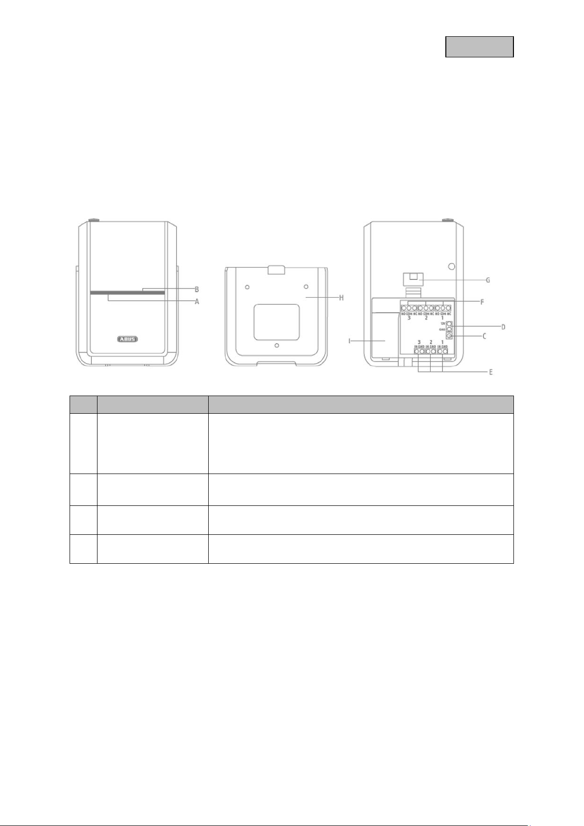
1.2. Device features
No Designation Comment
permanent red: power supply unit connected
A Status LED display
B
output LED display
C Link Button
D
Connection
flashes red: power supply unit disconnected, battery mode
Flashing green slowly: Product reset to factory settings
flashing green fast: Z-Wave Inclusion running
Flashes 2x green: signal input triggered
Flashes 2x red: relay output has been switched
Manual triggering of the wake-up command, inclusion, exclusion and
reset
For power supply with a 12V/1A power supply unit
6
Page 7
English
Attention: Under no circumstances may
Attention: Under no circumstances may
For the connection of
Analogue sensors with voltage 0~12V
Digital sensors with voltage 0~12V
Potential-free outputs NC/NO
Open Collector Outputs OC
functions:
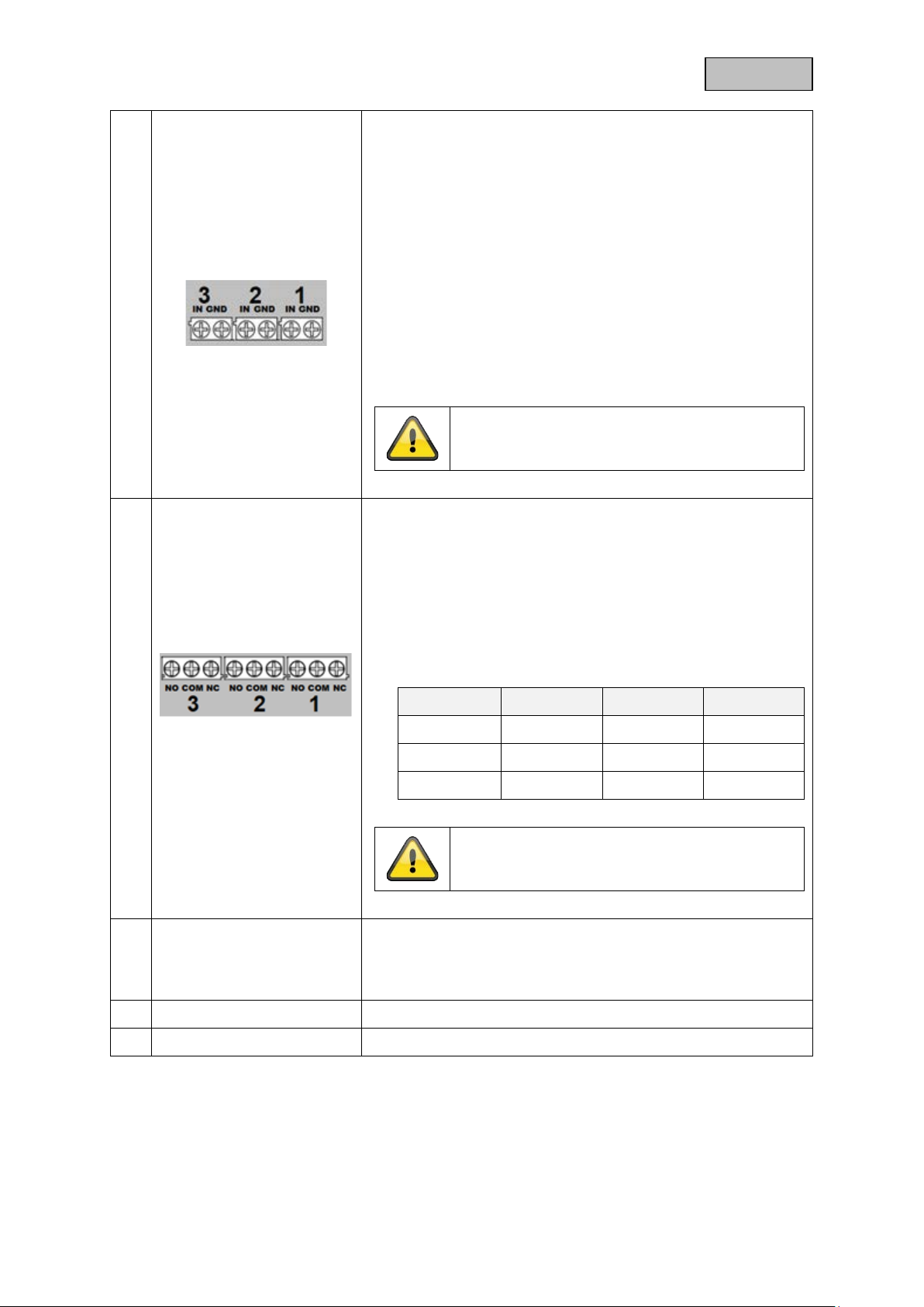
Signal input 1-3
E
Relay output 1-3
Selectable voltage level triggering threshold (see
configuration settings)
Activation/deactivation of the internal 3.3V voltage for
classic wire detectors
Input overvoltage protection (also works when the
input voltage is above the supply voltage)
periodic report of the voltage level to the controller
products with higher voltage, e.g. 230VAC, be
connected.
For connecting actuators with a maximum of 24VDC
SPDT (Single Pole, Double Throw) relay (toggle switch)
functions:
Configurable timer that switches off automatically after
a preset period of time (default is 500 ms)
The output can be set to activate automatically when
the input terminals
(see configuration setting)
Maximum power Volt/Ampere:
F
G Sabotage contact
H Backplate For mounting on the wall
I Battery compartment Observe polarity
Pressing the sabotage contact for 6 seconds activates the
sabotage protection.
Afterwards, sabotage alarm is triggered when the contact is
opened.
Relay Max. V NO Pin NC pin
OUT 1 24V DC 10A 5A
OUT 1 24V DC 3A 3A
OUT 1 24V DC 3A 3A
products with higher voltage, e.g. 230VAC, be
connected.
7
Page 8

English
1.3. Operating principle
The PLHA10100 was developed for use in a larm and hom e autom ation s ystem s that use the Z -Wave
wireless standard. The device has the following functions:
Integration of wired sensors and actuators into the Z-Wave wireless protocol
Three signal inputs
Three relay outputs
Emergency power supply and sabotage protection
1.4. Performance features
The device..:
...is Z-Wave Plus compatible & certified
...supports the Z-Wave S2 standard (Security 2)
1.5. Use in systems of different manufacturers
Communication is via the Z-Wave EU frequency (868.4 Mhz). You can integrate the device into any ZWave network with a certified Z-Wave controller, regardless of the manufacturer. All non-battery
powered nodes in the network act as amplifiers to amplify the wireless communication of the network.
1.6. DSK code
The DSK code (Device-Specific-Key) is the device-specific key of your device and is required for secure
teach-in (inclusion) via S2 on t he Z-W ave controller. The firs t 5 digits of th e DSK Code can be f ound
under the QR Code on the back of the product. Please enter them in the inclusion process when
prompted. Alternat ively, you can transfer th e ent ir e D SK code that you find on th e e nc lose d DSK card
to the Z-Wave controller via QR Code Scan. Please keep the DSK card in a safe place!
Hint:
We recommend secur e S2 inclus ion (m ust be s upported by the Z -W ave control ler) Please enter the 5
digits of the DSK code (bottom of the device) or the entire DSK code (QR code) when prompted.
8
Page 9

English
he battery
2. Functional overview
2.1. Inclusion / Teach-in device
This product supports SmartStart:
SmartStart-enab led products can be add ed to a Z-Wave network by scanning the Z-Wave QR code
present on the product with a controller that provides SmartStart integration. No further action is
required, and the SmartStart product will be automatically added near the network within 10 minutes of
power-up.
Remove the back cover and open t
compartment.
Connect the power supply unit and remove the contact
strip on the battery compartment.
Activate the inclus ion mode (teach-in mode) on the ZWave controller. (f or more details, please refer to t he
Z-Wave controller's user manual)
Press the "+" button (A dd / Inclusion) in your Z-Wave
app and follow the instructions to set the Z-Wave
controller into inclusion mode.
Press the Link button 3 times quickly (within 1.5
seconds) to start the inclusion on the device. The LED
starts flashing green quickly.
9
Page 10

English
Successful inclusio n is displa yed in the app or on the
Z-Wave controller and the status LED on the dev ice
stops flashing.
Repeat the inclusion process if it was not successful.
If a new attempt fails as w ell, first carry out a factor y
reset on the device, see 2.4.
2.2. Planning, assembly and installation
The device uses low power radio signals to communicate with the Z-Wave controller. For best
results, please note the following:
The device has a radio range of up to 40 m.
Due to its design, the device is only suitable for surface mounting indoors.
Example installation:
Please observe the safety instructions:
The maximum voltage of the devices to be connected is 12 volts for the
inputs and 24 volts for the outputs.
Attention: Under no circumstances may products with higher voltage,
such as 230VAC, be connected.
Screw the bracket to the wall.
Variant 1:
Ideally, use a flush-mounted box as storag e s pac e f or
the cables. The ho lder has a corresponding op ening
and the battery compartment has a predetermined
breaking point, which you can open carefully with a
cutter knife, for example. T his allo ws the cables to be
inserted into the product from behind.
Variant 2:
10
Page 11

English
Alternatively, the cabl es can als o be surf ace-mounted
1
2
and inserted from below.
Wire the devices to be connected in accordance with
the instructions in Chapter 1.2. and the safety
instructions.
Use the integrated train protection.
Leave enough clearance for the cables during wiring
to still be able to remove the device from the wall.
Then place the device on the wall bracket, the tamper
protection is activated automatically after 6 seconds.
11
Page 12

English
2.3. Exclusion / teach-in device
Activate the exclusion mode (learn mode) on the ZWave controller. (f or more details, please refer to t he
Z-Wave controller's user manual)
Or press the "-" button (Remove / Exclusion) in your ZWave app and follow the instructions to set the Z-Wave
controller to Exclusion mode.
Press the Link button 3 times quickly (within 1.5
seconds) to start the exclusion on the device.
The successful exclusion is displayed in the app or on
the Z-Wave controller
2.4. Reset to factory settings
Press the Link button 3 times quickly (within 1.5
seconds).
Press quickly (within 1 second)
a fourth time and press an d hold the Link button f or at
least 5 seconds.
The device is now reset to factory settings.
Hint:
This procedure should only be used if the primary
network controller is not capable of acting.
If the device is set to factor y default, the status is set
to "not included" and the association settings and
possible configurations are reset to default.
12
Page 13

English
3. Advanced Z-Wave Parameters
3.1. Association Groups
Z-Wave devices can con tro l other de vices direct ly. T his direct c ontrol is call ed ass ociation in Z -Wave.
The device ID of the device to be contr olled m ust be s tored in the c ontrol ling devices . This is done in
so-called association groups. An association group is always linked to an event in the controlling device
(keystroke or trigger ing of a sensor). W hen this event occ urs, a control comm and - usually a BASIC
SET - is sent to all devices stored in an association group.
The device supports the following association groups:
Group-
Number
1 5 Lifeline General
2 5
3 5
4 5
1 0 Lifeline General Mirroring the root device
2 5
Maximum
Devices
Group name Profile command class
Device Reset Locally
notification report
Switch Binary Report
Sensor Multilevel Report
battery report
On / Off Control
(signal input 1)
On / Off Control
(signal input 2)
On / Off Control
(signal input 3)
On / Off Control
(signal input 1)
Notification
Notification
Notification
End point 1
Notification basic set
End point 2
Mirroring Endpoint 1, Group 2
(basic set)
Mirroring Endpoint 2, Group 2
(basic set)
Mirroring endpoint 3, group 2
(basic set)
1 0 Lifeline General Mirroring the root device
2 5
1 0 Lifeline General Mirroring the root device
2 5
On / Off Control
(signal input 2)
On / Off Control
(signal input 3)
Notification basic set
End point 3
Notification basic set
13
Page 14

English
Group 1 (the Z-Wave controller)
The Lifeline Association is automatically established bet ween the Z-Wave controller and the
device at inclusion and defines what information is exchanged between the Z-Wave controller
and the device.
Group 2, 3 and 4 (direct association with up to 5 terminals)
When a signal input (IN 1-3) is triggered, the unit first sends a BASIC Set ON. When the
preset timer expires, it sends a BASIC Set OFF.
Multi Channel
Sensor Multilevel Command Class End point 1
Switch Binary Command Class End point 4
Basic Command Class End point 4
:Root map (Association Group Information)
3.2. WakeUp Time
The device is an A lwa ys On S lave and therefore d oes not r equire a W ak eUp func tion. The device can
be controlled by the Z-Wave controller at any time.
14
Page 15

English
0x00
0x00
0x00
0x02
0x02
3.3. Reports
notification report
Event Type
Current is applied for the first time 0x08 0x01
Power supply unit separated 0x08 0x02
Power supply unit connected again 0x08 0x03
Sabotage alarm
(Sabotage contact opened after it was closed
for more than six seconds)
Sabotage alarm acknowledgement (sabotage
contact is pressed for more than six seconds)
Input was triggered 0x07 0x02 0x00
Signal input was triggered 0x07 0x00 0x01
Signal input Acknowledgement 0x07 0x00 0x01
Signal input Armed
(If set as Armed / Disarmed input in
configuration parameter 18)
Signal input Disarmed
(If set as Armed / Disarmed input in
configuration parameter 18)
0x07 0x03
0x07 0x00
0x06 0x01 0x00
0x06 0x01 0x00
Attribute Parameters
Length
0x00
0x01
Event
Parameters
0x03
battery report
Battery message for the backup battery
Value Description
0x14 - 0x64
(20 – 100)
0xFF
(256)
Sensor Multilevel report
Report about voltage in millivolts at the 3 signal inputs
Description Type Precision
Voltage 0x0F 1
Measured
variable
millivolts
(mV)
Battery charge level in percent (%)
Low battery
(or no battery)
Size Value
2 bytes
0x0000 - 0xFFFF
(-32767mV - 32767mV)
15
Page 16

English
Switch Binary report
Sends report when rel a y outputs 1-3 are switched on or off.
Value Description
0x00
(0)
0xFF
(256)
(There is a delay of 2 seconds for the automatic shutdown after the shutdown is completed. )
Device Reset Locally Report
A "Device Reset Locally" report is sent when the device is reset to factory settings.
Relay is off
Relay is on
16
Page 17

English
Bit
7 6 5 4 3 2 1
0
Bit value
1 1 0 0 0 0 1
0
Decimal value
128
64
32
16 8 4 2 1
128 + 64 + 2 = 194
3.4. Overview Configuration Parameters
Z-Wave products ca n be used direc tly after inc lusion in the net work. However , configuratio n settings
can be used to adapt the behaviour of the device even better to the requirements of the application and
to activate additional functions.
For signal input 1 and relay output 1
Para-
meter
Byte
size
Function
1 1 Si gnal input 1 - Mode
Default
value
64
(01000000)
Description
Several settings of the signal input and its
triggering behaviour. Binary number (8 bits)
must finally be converted into a decimal
number.
Bit 0: Must be 0
Bit 1:
0 = nothing happens
1 = Relay output 1 is switched when
tripped
Bit 2:
0 = nothing happens
1 = Relay output 2 is switched when
tripped
Bit 3:
0 = nothing happens
1 = Relay output 3 is switched when
tripped
Bit 4: Must be 0
Bit 5: Must be 0
Bit 6:
0 = No voltage present at signal input
1 = 3.3V is present at the signal input
Bit 7: (Depending on parameter 4/5)
0 = Trip when voltage falls below low
threshold Acknowledgement when
voltage rises above high threshold
1 = Tripped when voltage rises above
high threshold. Acknowledgement when
voltage drops below low threshold
Example:
Signal input triggers above high threshold, 3.3V
is applied and on triggering
Relay output 1 switched
(Hexadecimal: 0x00 - 0xFF)
17
Page 18

English
2 1
3 1
4 1
5 1
Relay output 1 -
switching time
Signal input 1 -
switching time at
association group 2
Signal input 1 -
voltage high
threshold
Signal input 1 - Low
voltage threshold
5
180
25
10
Setting for the duration of the switching time
when the relay output is switched.
Adjustable from 1 - 256 in 100ms steps
(5 = 500ms = 0.5s)
0 = relay output is permanently switched
(Hexadecimal: 0x00 - 0xFF)
Setting for the duration of the switching time at
association group 2 when signal input is
triggered.
Adjustable from 1 - 256 in seconds
0 = Switched permanently
(Hexadecimal: 0x00 - 0xFF)
Setting, from which voltage rise the signal input
triggers or acknowledges.
Adjustable from 0 - 256 in 100mV steps
(25 = 2500mV = 2.5V)
(Hexadecimal: 0x00 - 0xFF)
Setting of the voltage drop below which the
signal input is triggered or acknowledged.
Adjustable from 0 - 256 in 100mV steps
(10 = 1000mV = 1.0V)
(Hexadecimal: 0x00 - 0xFF)
For signal input 2 and relay output 2
Para-
meter
6 1 Si gnal input 2 - Mode
7 1
8 1
9 1
10 1
Byte
size
Function
Relay output 2 -
switching time
Signal input 2 -
switching time at
association group 3
Signal input 2 -
voltage high
threshold
Signal input 2 - Low
voltage threshold
Default
value
64
(01000000)
5
180
25
10
Description
Identical to parameter 1.
Concerns signal input 2
Bit 7 depending on parameter 9 and 10
Identical to parameter 2.
Concerns relay output 2
Identical to parameter 3.
Concerns Association Group 3
Concerns signal input 2
Identical to parameter 4.
Concerns signal input 2
Identical to parameter 5.
Concerns signal input 2
18
Page 19

English
For signal input 3 and relay output 3
Para-
meter
11 1 Signal input 3 - Mode
12 1
13 1
14 1
15 1
For signal input 3 and relay output 3
Para-
meter
11 1 Signal input 3 - Mode
Byte
size
Byte
size
Function
Relay output 3 -
switching time
Signal input 3 -
switching time at
association group 4
Signal input 3 -
voltage high
threshold
Signal input 3 - Low
voltage threshold
Function
Default
value
64
(01000000)
5
180
25
10
Default
value
64
(01000000)
Description
Identical to parameter 1.
Concerns signal input 3
Bit 7 depending on parameter 14 and 15
Identical to parameter 2.
Concerns relay output 3
Identical to parameter 3.
Concerns Association Group 4
Concerns signal input 3
Identical to parameter 4.
Concerns signal input 3
Identical to parameter 5.
Concerns signal input 3
Description
Identical to parameter 1.
Concerns signal input 3
Bit 7 depending on parameter 14 and 15
12 1
13 1
14 1
15 1
Relay output 3 -
switching time
Signal input 3 -
switching time at
association group 4
Signal input 3 -
voltage high
threshold
Signal input 3 - Low
voltage threshold
5
180
25
10
Identical to parameter 2.
Concerns relay output 3
Identical to parameter 3.
Concerns Association Group 4
Concerns signal input 3
Identical to parameter 4.
Concerns signal input 3
Identical to parameter 5.
Concerns signal input 3
19
Page 20

English
Bit
7 6 5 4 3 2 1
0
Bit value
0 0 0 0 1 0 1
0
Decimal value
8 + 2 = 10
General settings
Para-
meter
16 1
17 1
Byte
size
Function
Voltage Report
(time)
Sabotage Alarm
Relay output
Default
value
30
0
(00000000)
Description
The interval time of the volt age repor t for signal
input 1-3
Adjustable from 1 - 256 i n minutes
(Hexadecimal: 0x01 - 0xFF)
Setting whether a relay output must be
switched in case of a sabotage alarm. Binary
number (8 bits) must finally be converted into a
decimal number.
Bit 0: Must be 0
Bit 1:
0 = nothing happens
1 = Relay output 1 is switched when
tripped
Bit 2:
0 = nothing happens
1 = Relay output 2 is switched when
tripped
Bit 3:
0 = nothing happens
1 = Relay output 3 is switched when
tripped
Bit 4 - 7: Must be 0
Example:
Signal input -
18 1
Activate sharp /
blurred message
0
128 64 32 16 8 4 2 1
In case of sabotage alarm, relay output 1
and 3 triggered
(Hexadecimal: 0x02 - 0x0A)
Setting whether a signal input should send an
armed and an unarmed message instead of a
trip.
0 = No signal input
1 = Signal input 1 sends sharp/unsharp
message
2 = Signal input 2 sends Arm / Disarm
message
3 = Signal input 3 sends sharp/unsharp
message
(Hexadecimal: 0x00 - 0x03)
20
Page 21

English
3.5. Supported command classes
Command class Version
Association version 2
Association Group Info Version 1
Battery Version 1
Configuration Version 4
Device Reset Locally Version 1
Firmware Update Md Version 4
Manufacturer Specific version 2
multi-channel Version 4
Multi Channel Association Version 3
Notification Version 8
Power level Version 1
Security Version 1
Security 2 Version 1
Sensor Multilevel Version 5
Supervision Version 1
Switch Binary Version 1
Transport Service version 2
Version Version 3
ZwavePlus Info version 2
For endpoints 1-3
Command class Version
Association version 2
Association Group Info Version 1
Multi Channel Association Version 3
Notification Version 8
Sensor Multilevel Version 5
Supervision Version 1
ZwavePlus Info version 2
Endpoint 4~6
Command class Version
Association version 2
Association Group Info Version 1
Multi Channel Association Version 3
Supervision Version 1
Switch Binary Version 1
ZwavePlus Info version 2
21
Page 22

English
3.6. Supported security levels
Security S2 Authenticated
Security S2 Unauthenticated
Security S0 Authenticated
3.7. Description of the endpoints
Root End point 1-3 End point 4-6
Role Type
device type
generic type
specific type Notification Sensor Notification Sensor distressed
Requested security
keys
Notification Sensor
Sensor Notification
S0、S2 Un-Authenticated、S2-Authenticated
Endpoint Basic Command Mapped
1~3 Basic Command no
Always On Slave
Notification Sensor
Sensor Notification
binary switch
binary switch
4~6 Basic Set (value) Binary Switch Set (Value)
4~6 Basic Report(Value) Binary Switch Report (Value)
22
Page 23

English
4. Technical data
Parameters PLHA10100
Dimensions (W x H x D) 143 x 99 x 32 mm
Battery 4xAAA
Weight 216 g
Operating temperature >0° – 40°C
Location Interior
Radio frequency 868.42 MHz (Z-Wave Plus, Europe)
Modulation FSK (BFSK/GFSK)
Transmitting power: < 5 dbm
Power supply 9V-12V DC, 1A min
Firmware updateable Yes, OTA
Z-Wave manufacturer ID 0x0403
Z-Wave Product Type ID 0x0003
Z-Wave Device ID 0x0007
Z-Wave SmartStart supported Yes
Z-Wave Plus supports Yes
Z-Wave Network Security Yes
Z-Wave AES-128 Security (S0) Yes
Z-Wave S2 Security Yes (S2 Authenticated)
Z-Wave Repeater Function Yes
Z-Wave Chip Generation 500
23
 Loading...