

Page 1
ABUS embedded NVR
Date: 29/11/2017
Firmware: 3.4.8
Local user interface user guide
(basic instructions)
Page 2

This user guide contains important installation and
operation information.
Make sure that this user guide is handed over when the
product is given to other persons.
Keep this user guide to consult later.
You will find a list of contents with the corresponding
page numbers in the contents.
Page 3

Contents
Important safety information .......................................................................................................................................... 7
Explanation of symbols .................................................................................................................................................... 7
Intended use .................................................................................................................................................................... 7
General ............................................................................................................................................................................ 7
Power supply ................................................................................................................................................................... 7
Installation ........................................................................................................................................................................ 8
Children ............................................................................................................................................................................ 8
EU Directives ................................................................................................................................................................... 8
Compatibility .................................................................................................................................................................... 9
General ............................................................................................................................................................................ 9
Compatible recorders ....................................................................................................................................................... 9
Compatible video walls/decoders .................................................................................................................................... 9
Compatible IP cameras .................................................................................................................................................... 9
Compatible keyboards ................................................................................................................................................... 10
Compatible software ...................................................................................................................................................... 10
Supported camera functions .......................................................................................................................................... 10
Pre-play storage ............................................................................................................................................................. 10
Image display ................................................................................................................................................................. 10
External I/O connections and wiring ............................................................................................................................ 12
General .......................................................................................................................................................................... 12
Audio connections/2-way audio ..................................................................................................................................... 12
Alarm inputs ................................................................................................................................................................... 13
Alarm outputs ................................................................................................................................................................. 13
RS-485 output (NVR10030/NVR10040) ........................................................................................................................ 13
Keyboard output ............................................................................................................................................................. 14
Introduction .................................................................................................................................................................... 15
General information ....................................................................................................................................................... 15
Starting the device ......................................................................................................................................................... 15
On-screen keyboard ...................................................................................................................................................... 15
Switching off the device, locking, rebooting ................................................................................................................... 16
Setup wizard ................................................................................................................................................................... 17
Setting up the system .................................................................................................................................................... 17
System time and date .................................................................................................................................................... 18
Network settings ............................................................................................................................................................ 18
Hard disk drive management ......................................................................................................................................... 19
Camera assistant ........................................................................................................................................................... 19
Camera recording .......................................................................................................................................................... 19
Live view ......................................................................................................................................................................... 20
General information on live image ................................................................................................................................. 20
Live image function areas .............................................................................................................................................. 20
Menu bar operation ........................................................................................................................................................ 20
Multiview control ............................................................................................................................................................ 20
Action bar operation ....................................................................................................................................................... 21
PTZ control menu .......................................................................................................................................................... 21
Recording Status ........................................................................................................................................................... 22
Right-click menu ............................................................................................................................................................ 22
Password note ............................................................................................................................................................... 22
Playback view ................................................................................................................................................................. 23
General information on playback ................................................................................................................................... 23
Action bar operation ....................................................................................................................................................... 23
3
Page 4

Contents
Playback control ............................................................................................................................................................ 23
Smart Search ................................................................................................................................................................. 24
Audio control .................................................................................................................................................................. 24
Export functions ............................................................................................................................................................. 24
Export management ...................................................................................................................................................... 25
Operation time bar and calendar ................................................................................................................................... 25
Camera list operation ..................................................................................................................................................... 26
Selecting playback type ................................................................................................................................................. 26
Playback: Normal .......................................................................................................................................................... 27
Playback: Event ............................................................................................................................................................. 27
Playback: Tag ................................................................................................................................................................ 27
Playback: Multi-Timeshift .............................................................................................................................................. 27
Playback: External File .................................................................................................................................................. 28
Playback: Image ............................................................................................................................................................ 28
Info menu ........................................................................................................................................................................ 29
General information menu ............................................................................................................................................. 29
Settings ........................................................................................................................................................................... 30
General information on settings ..................................................................................................................................... 30
Setting: Configuration ................................................................................................................................................... 31
General information on configuration ............................................................................................................................. 31
General .......................................................................................................................................................................... 32
General tab .................................................................................................................................................................... 32
DST Settings tab ........................................................................................................................................................... 32
More Settings tab .......................................................................................................................................................... 32
Network .......................................................................................................................................................................... 33
General tab .................................................................................................................................................................... 33
DDNS tab ...................................................................................................................................................................... 34
NTP tab ......................................................................................................................................................................... 34
Email tab ........................................................................................................................................................................ 34
SNMP tab ...................................................................................................................................................................... 35
NAT TAB ....................................................................................................................................................................... 35
More Settings tab .......................................................................................................................................................... 36
Alarm .............................................................................................................................................................................. 37
Alarm Status tab ............................................................................................................................................................ 37
Alarm Input tab .............................................................................................................................................................. 37
Alarm output tab ............................................................................................................................................................ 37
Linkage action ................................................................................................................................................................ 38
Trigger channel tab ....................................................................................................................................................... 38
Arming Schedule tab ..................................................................................................................................................... 38
Linkage action tab ......................................................................................................................................................... 39
PTZ linking tab............................................................................................................................................................... 39
RS-232 ........................................................................................................................................................................... 39
Live view ........................................................................................................................................................................ 39
General tab .................................................................................................................................................................... 39
View tab ......................................................................................................................................................................... 40
Exceptions ..................................................................................................................................................................... 40
User ................................................................................................................................................................................ 41
Local configuration tab .................................................................................................................................................. 42
Remote configuration tab .............................................................................................................................................. 42
Camera configuration tab .............................................................................................................................................. 42
Hot spare........................................................................................................................................................................ 42
Setting up hot spare mode ............................................................................................................................................ 43
Setting: Camera ............................................................................................................................................................. 44
General information on managing cameras................................................................................................................... 44
4
Page 5

Contents
Camera .......................................................................................................................................................................... 44
IP Camera tab ............................................................................................................................................................... 44
IP camera import/export tab .......................................................................................................................................... 46
OSD ............................................................................................................................................................................... 46
Image ............................................................................................................................................................................. 47
PTZ ................................................................................................................................................................................ 47
Motion ............................................................................................................................................................................ 48
Private Zone ................................................................................................................................................................... 48
Tamper Surveillance ...................................................................................................................................................... 49
Video Loss ..................................................................................................................................................................... 49
VCA ................................................................................................................................................................................ 49
Setting: Recording ......................................................................................................................................................... 51
General information on recording .................................................................................................................................. 51
Schedule ........................................................................................................................................................................ 51
Recording/instant image tab .......................................................................................................................................... 51
Parameter ...................................................................................................................................................................... 52
Record tab ..................................................................................................................................................................... 53
Substream tab ............................................................................................................................................................... 53
Instant image tab ........................................................................................................................................................... 54
Advanced settings .......................................................................................................................................................... 54
Holiday ........................................................................................................................................................................... 55
Setting: HDD ................................................................................................................................................................... 56
General information on HDD.......................................................................................................................................... 56
General .......................................................................................................................................................................... 56
Advanced settings .......................................................................................................................................................... 57
Disk mode tab................................................................................................................................................................ 57
Storage mode tab .......................................................................................................................................................... 58
Clone drive tab .............................................................................................................................................................. 59
RAID ............................................................................................................................................................................... 60
Physical disk tab ............................................................................................................................................................ 60
Array tab ........................................................................................................................................................................ 60
Firmware tab .................................................................................................................................................................. 60
Panic recording .............................................................................................................................................................. 61
General information on panic recording ......................................................................................................................... 61
Recording ....................................................................................................................................................................... 61
Continuous Capture ....................................................................................................................................................... 62
Alarm .............................................................................................................................................................................. 62
VCA search ..................................................................................................................................................................... 63
General information on VCA search .............................................................................................................................. 63
Behaviour Search .......................................................................................................................................................... 63
Face Search ................................................................................................................................................................... 64
People Counting ............................................................................................................................................................ 65
Video Export ................................................................................................................................................................... 66
General information on video export .............................................................................................................................. 66
Duration/Event/Image .................................................................................................................................................... 66
Maintenance ................................................................................................................................................................... 68
General information on maintenance ............................................................................................................................. 68
System Info .................................................................................................................................................................... 69
Log search ..................................................................................................................................................................... 69
Import/Export ................................................................................................................................................................. 70
Update............................................................................................................................................................................ 70
Default ............................................................................................................................................................................ 70
5
Page 6

Contents
Net Detect ...................................................................................................................................................................... 71
Traffic tab ....................................................................................................................................................................... 71
Network Detection tab ................................................................................................................................................... 71
Network Stat. tab ........................................................................................................................................................... 72
HDD Detect .................................................................................................................................................................... 72
Checking the hard disk drive status .............................................................................................................................. 72
Fault rectification ........................................................................................................................................................... 73
Disposal .......................................................................................................................................................................... 73
Notes on EC directives for waste electrical and electronic equipment .......................................................................... 73
Notes on RoHS EU Directive ......................................................................................................................................... 73
6
Page 7
Indicates a risk of injury or health
Indicates a risk of injury or health
Indicates possible damage to the
Important safety information
Important safety information
Explanation of symbols
The following symbols are used in this manual and on the
device:
Symbol
The following annotations are used in the text:
Meaning
1. …
2. …
…
…
Intended use
Only use the recorder for the purpose for which it was
built and designed. Any other use is considered
unintended!
This device may only be used for the following
purpose(s):
This recorder is used in combination with video signal
sources (network cameras) and video output devices
(TFT monitors) for object surveillance.
Note
Data storage is subject to national data privacy
guidelines.
When carrying out the installation advise your
customers of the existence of this guideline.
Signal
Meaning
word
Warning
hazards.
Warning
hazards caused by electrical
voltage.
Important
device/accessories.
Note Indicates important information.
Required action to be carried out in a set order
List without a set order, given either in the text
or warning notice
General
Before using this recorder for the first time, please read
the following instructions carefully and observe all
warning information, even if you are familiar with the use
of such recorders.
Warning
All guarantee claims are invalid in the event of
damage caused by non-compliance with this user
manual.
We cannot be held liable for resulting damage.
Warning
In the event of personal or material damage
caused by improper operation or non-compliance
with the safety information, we cannot be held
liable.
All guarantee claims are void in such cases.
Retain this handbook for future reference.
If you sell or pass on the recorder to third parties, you
must include these instructions with the device.
Power supply
Warning
Prevent data loss.
The recorder should only ever be used with a
device that is constantly connected to an
uninterruptible power supply UPS with surge
protection.
Warning
Modifications to the device invalidate the
guarantee.
7
Page 8

Important safety information
Center GmbH does not accept any
Installation
Observe all safety and operating instructions before
installing the device for the first time.
Only open the housing to install the hard disk drive.
Only install the software on devices that are
expressly suitable for the intended purpose.
Otherwise, damage to the device can occur.
Note
Compatible devices:
- NVR10010
- NVR10020
- NVR10030
- NVR10040
Warning
If in doubt, have the device installed by a
specialist technician.
All company names and product descriptions are
trademarks of the corresponding owner. All rights
reserved.
If you have any questions, please contact your specialist
installation contractor or specialist dealer.
Disclaimer
This user guide has been produced with the
greatest of care. Should you identify any
omissions or inaccuracies, please contact us at
the address shown on the back of the guide.
ABUS Securityliability for technical and typographical errors, and
reserves the right to make changes to the product
and user guides at any time and without prior
warning. ABUS Security-Center GmbH is not
liable or responsible for direct or indirect damage
resulting from the equipment, performance and
use of this product. No guarantee is made for the
contents of this document.
Do not allow electrical devices to be handled by children.
Do not leave children unsupervised.
Children
Do not allow electrical devices to be handled by
children. Do not allow children to use electrical
devices unsupervised. Children may not properly
identify possible hazards. Small parts may be fatal if
swallowed.
Keep packaging film away from children. There is a
risk of suffocation.
This device is not intended for children. If used
incorrectly, parts under spring tension may fly out and
cause injury to children (e.g. to eyes).
EU Directives
This device complies with the requirements of the EU
Low Voltage Directive (2014/35/EU), the EMC
Directive (2014/30/EU) and the RoHS Directive
(2011/65/EU). The declaration of conformity can be
obtained from:
ABUS Security-Center GmbH & Co. KG
Linker Kreuthweg 5
86444 Affing
GERMANY
To ensure this condition is maintained and that safe
operation is guaranteed, it is your obligation to observe
this user guide.
Please read the entire user manual carefully before
putting the product into operation, and pay attention to all
operating instructions and safety information.
8
Page 9
Device type
Item number
Device type
Item number
IP camera type
Item number
Compatibility
Compatibility
General
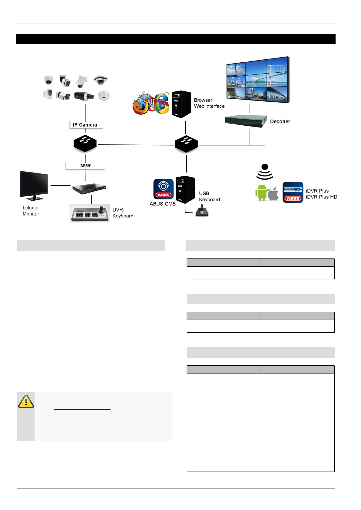
ABUS embedded recorders are compatible with a
variety of cameras and additional components. Check
the compatibility with your device and limitations to the
use of the components before use.
Some functions of this recorder (firmware) depend on
the connected devices (e.g. fisheye view of
hemispheric cameras or PTZ cameras).
Please keep in mind that older devices may not be
supported or may be only partially supported.
Note
Check http://www.abus.com to find any additional
information on compatibility with your
camera/recorder.
The following tables show the current versions at
the time of publication of this guide (Q1/2017).
Compatible recorders
NVR
NVR10010, NVR10020,
NVR10030, NVR10040
Compatible video walls/decoders
Video Wall Decoder
TVAC26100, TVAC26110,
TVAC26120, TVAC26130
Compatible IP cameras
IP Camera
TVIP11560, TVIP41500,
TVIP41560, TVIP52502,
TVIP61500, TVIP61550,
TVIP61560, TVIP70000,
TVIP72000, TVIP91100,
TVIP91300, TVIP91600,
TVIP91700, TVIP92100,
TVIP92300, TVIP92500,
TVIP92600, TVIP92610,
TVIP92700, IPCA33500,
IPCA53000, IPCA63500,
IPCA66500, IPCA73500,
IPCA76500, IPCB42500,
IPCB42550, IPCB71500,
IPCB72500, IPCS10020,
IPCS62520, IPCS72520
9
Page 10
Compatibility
Device type
Item number
Device type
Item number
Device type
Item number
IP camera PT/Z
IP camera Hemispheric
TVIP21560, TVIP41660,
TVIP81000, TVIP81100,
TVIP82000, TVIP82100,
IPCS82502, IPCS82500
TVIP82900, TVIP83900,
TVIP86900
ONVIF
RTSP
See http://www.abus.com
(recorder download area)
RTSP streaming profile
Compatible keyboards
PTZ/DVR control panel TVAC26000
USB keyboard
TVAC26010
(only in connection with
ABUS CMS)
Compatible software
ABUS CMS TVSW11000
iDVR Plus
(Smartphone)
iDVR Plus HD
(Tablet)
ABUS IP installer TVSW12000
APP12300 (iOS)
APP12500 (Android)
APP12400 (iOS)
APP12600 (Android)
Pre-play storage
Unlike flexible PC systems, embedded recorders have
a hardware configuration which is tailored to their
intended purpose. As a consequence, the desired
recording schedule cannot always be achieved in the
special case of pre-play recordings. The available
working memory is a crucial parameter for the pre-play
recording schedule. Depending on the model,
embedded recorders have between 512 MB–2 GB of
working memory to manage all the background
processes of all cameras. In order to create pre-play
recordings, the information for each individual camera,
depending on the resolution, bitstream settings and
pre-play schedule, must be permanently kept in the
memory. A pre-alarm memory of a few seconds is
already hard to achieve with the use of 1080p
cameras. The higher the resolution of the cameras and
the more cameras connected to the recorder, the lower
the chance of having enough memory ready for all
cameras. Due to the variety of models and
configuration settings, as well as the complexity of the
evaluation of current scenes, we cannot provide a
reliable value for the pre-alarm memory. As a result,
we recommend using continuous recording for critical
cameras and then using the Smart Search to easily
filter out events.
Image display
Supported camera functions
Smart Search
(possibly not all functions
depending on the model)
Virtual alarm inputs and
outputs
VCA
(restrictions in creating
the VCA event images
depending on the model)
IPCA33500, IPCA53000,
IPCA63500, IPCA66500,
IPCA73500, IPCA76500,
IPCS10020, IPCA62520,
IPCA72520, IPCA66500,
IPCA73500, IPCA76500,
IPCB42500, IPCB42550,
IPCB71500, IPCB72500,
IPCS10020, IPCS62520,
IPCS72520
IPCA33500, IPCA53000,
IPCA63500, IPCA66500,
IPCA73500, IPCA76500,
IPCS10020, IPCA62520,
IPCA72520, IPCA66500,
IPCA73500, IPCA76500,
IPCB42550, IPCB71500,
IPCB72500, IPCS10020,
IPCS62520, IPCS72520
IPCA33500, IPCA53000,
IPCA63500, IPCA66500,
IPCA73500, IPCA76500,
IPCA62520, IPCA72520,
IPCA66500, IPCA73500,
IPCA76500
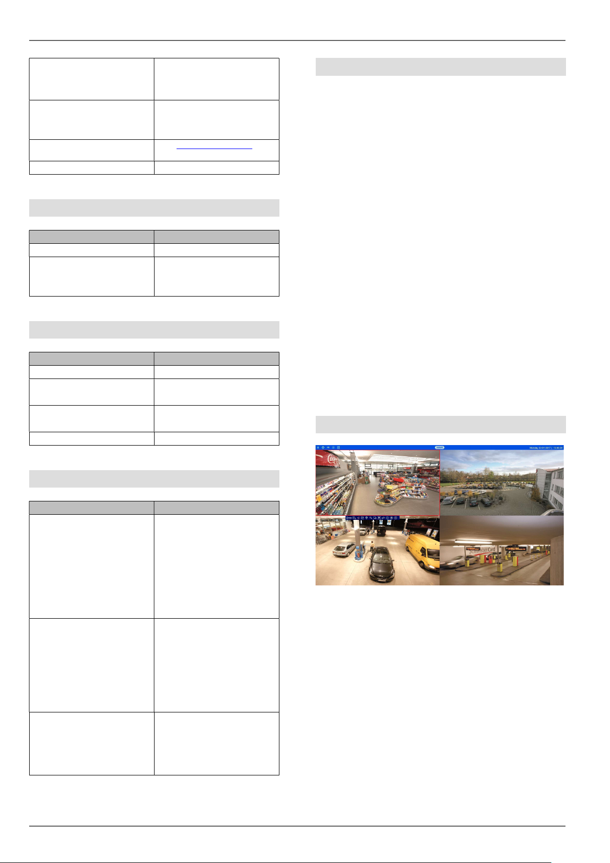
In order to display the IP camera video streams
(including live images and the playback of recordings)
via the local video output on the recorder
(VGA/HDMI/BNC), the digitally compressed data from
the recorder must be “decoded”. This process requires
processing power on the recorder sufficient for the
camera’s resolution. The higher the resolution and
bitrate of the camera stream, the higher the required
processing power on the recorder for the decoding
process.
10
Page 11
Resolution
Number of decodable cameras
720p
1080p
3 MPx
6 MPx
Compatibility
Warning
When problems/limitations in the local live image
view occur when the device is operating, bear this
information in mind.
If the number of camera streams to be displayed
exceeds the decoding performance of the recorder, the
following notification will appear on the monitor:
NO RESOURCE
For this reason, the substream of each camera will be
displayed automatically in the multi-view live views with
more than 4 channels (greater than 2x2). The
substream of a camera is therefore usually set to 720p
or lower.
In the playback view, the cameras will be played in
their respective recording quality (main stream).
Depending on the application and camera type, it is
possible that not all cameras will be able to be
displayed at once. As such, you should split up the
cameras into different views in order to avoid any
limitations.
Note
The NVR systems NVR10010, NVR10020,
NVR10030 and NVR10040 have a decoding
performance of 16 x 1080p.
The following stream configurations are possible for
local image output:
64 cameras
16 cameras
8 cameras
4 cameras
During remote playback by browser, CMS software or
app, the remote device undertakes the decoding
process (in order to display the images on the PC
monitor/smartphone) and therefore does not impact on
the processing power of the recorder.
11
Page 12
External I/O connections and wiring
Connection
Description
External I/O connections and wiring
General
The ABUS embedded recorders are equipped with
external interfaces for the control of alarm contacts, PTZ
cameras, keyboards and audio devices. The structure
level of the connections depends on the recorder model.
The larger the structure level of the recorder, the more
connections are normally present on the device.
Note
In your recorder’s quickstart manual or at
http://www.abus.com, you will find an exact listing
of the external interfaces in the technical data.
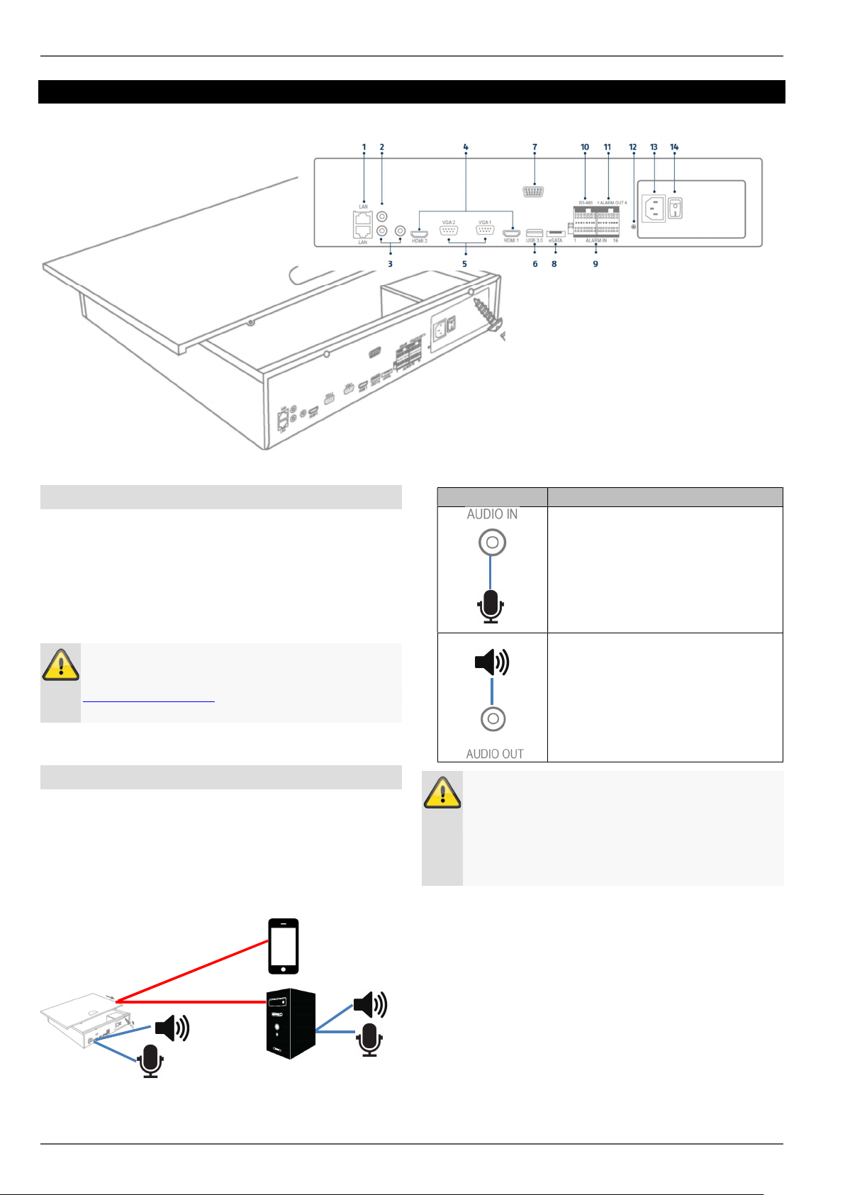
Audio connections/2-way audio
The audio connections on the recorder are only used for
remote 2-way audio communication via a network
connection. This can take place via the web interface on
the recorder, via the ABUS CMS software or via the iDVR
Plus app. The system configuration for this purpose is as
follows:
Network
Audio OUT
Mic IN
Audio IN
RCA audio input for the connection
of a separate microphone for 2way audio communication. If the
volume is too low, use an
additional preamplifier to raise the
signal levels of the microphone
input.
RCA audio output for the
Note
If the 2-way audio communication takes place via
a PC, you must ensure that a microphone and
loudspeaker are connected. In order to use the
web browser function, the ABUS recorder plug-in
must be installed.
Line OUT
connection of a separate
loudspeaker for 2-way audio
communication. Passive
loudspeakers must be connected
via a locked amplifier.
12
Page 13
normal state (NO/NC) and the event reaction must
Connection
Description
Co
nnection
Description
Connection
Description
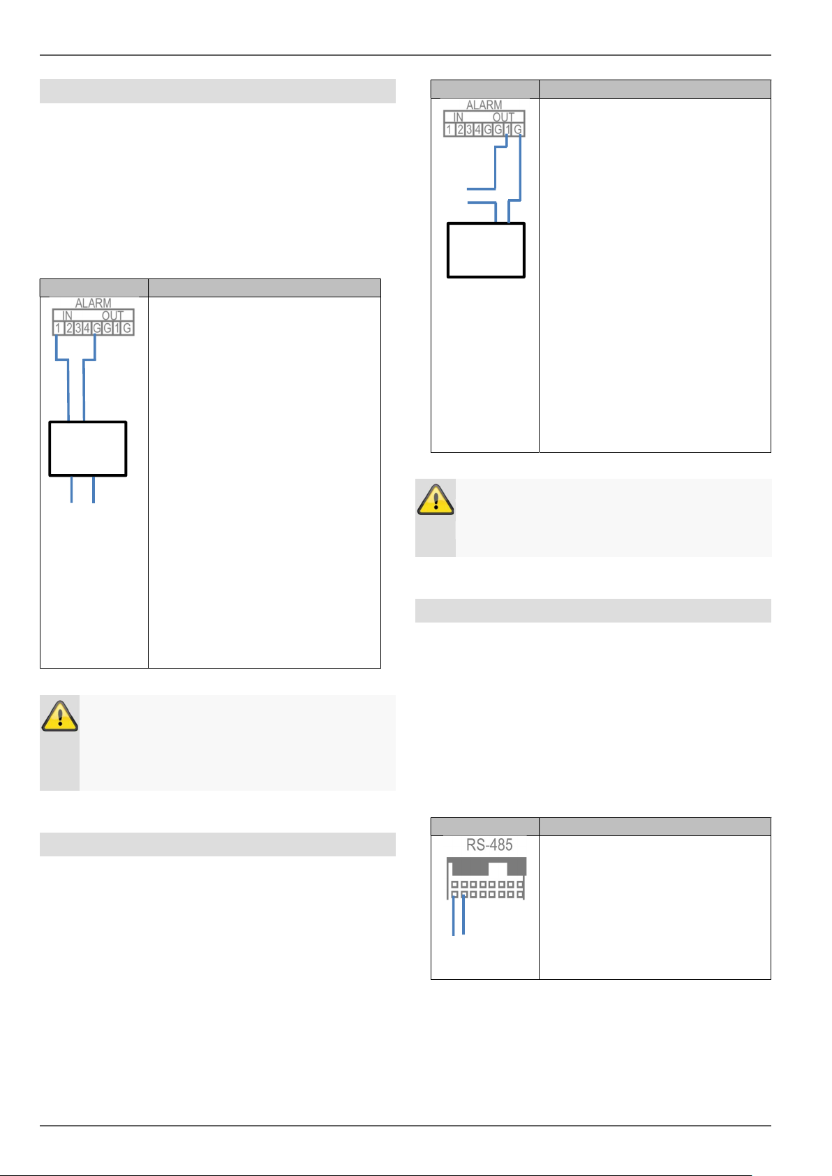
Alarm inputs
The alarm inputs on the recorder are used for event
control via externally wired detectors (door contacts,
motion detector, smoke detector, light barriers, etc.). On
the recorder side, the inputs can be used to activate a
recording, alert via CMS or send an alarm email, among
other things. The alarm inputs are purely switch contacts
(Normally Open/Normally Closed) which must not be
voltage controlled.
Depending on the recorder model,
1–16 inputs are available. First,
plug the detector contact in an
open input (IN1-16) and then
connect the grounding contact (G).
Connect more detectors in the
same way:
IN1 G
IN2 G
IN3 G
….
IN16 G
It does not matter whether you
connect all detectors to one
grounding contact or divide them
up among the available contacts.
Use terminal blocks in order to
connect multiple detectors to one
grounding contact.
Detector
s
_
Note
Following the connection of the detector to the
alarm input of the recorder, the behaviour in the
be programmed in the settings menu.
External I/O connections and wiring
Depending on the recorder model,
1–8 outputs are available. First,
_
Actuator
Note
After the actuator has been connected to the
alarm input of the recorder, the event reaction
must be programmed in the settings menu.
plug the actuator/device in an
open output (OUT1-8) and then
connect the grounding contact (G).
Connect further actuators in the
same way:
OUT1 G
OUT2 G
OUT3 G
….OUT8 G
It does not matter whether you
connect all actuators to one
grounding contact or divide them
up among the available contacts.
Use terminal blocks in order to
connect multiple actuators to one
grounding contact.
RS-485 output (NVR10030/NVR10040)
The RS-485 output on the recorder is used to control
analogue PTZ cameras.
IP cameras with an integrated PTZ function are fully
controlled via the network.
The use of the interface is intended as an alternative for
the use of IP cameras with external motor control.
Alarm outputs
The alarm outputs on the recorder are used for the action
control of externally wired devices/actuators (sirens,
lamps, door openers, etc.). The alarm output switching
takes place via integrated relays on the recorder. In order
to prevent damaging the relay/recorder, the device’s
maximum switching power must not exceed the specified
values of 12 V / 1 A.
13
Connect the PTZ control by using
the Transmit and Receive pins.
Only available on
NVR10030/NVR10040 !
-
Page 14

External I/O connections and wiring
Connection
Description
Keyboard output
The keyboard output on the recorder is used to control
the recorder using the optional keyboard (TVAC26000).
The local recorder functions can alternatively (instead of
using a mouse) be called up by using the external
keyboard.
Connect the keyboard using
connections D- and D+ on the
interfaces DVR-CON Ta and Tb.
14
Page 15
Introduction
General information
This handbook describes the commissioning and use of
the ABUS embedded recorder via the local user
interface.
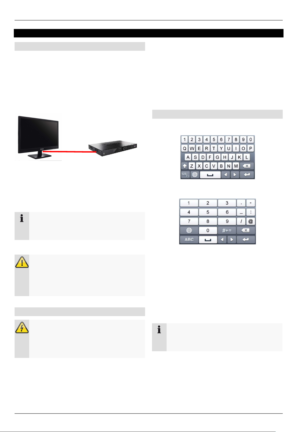
For this purpose, the recorder must be connected to a
monitor using the VGA/HDMI interface. During
operation, use the USB mouse which was included in
the scope of delivery.
We recommend that you complete the initial setup using
the local interface in order to set up basic settings like
the network address and the hard disc drive
configuration.
Introduction
1. During the start-up procedure, the device carries
out a self-test (blue LED will blink).
2. The start-up procedure is complete when the
blue LED is lit continuously.
3. Subsequently, the setup wizard (during the first
system start) or the live image display of the
cameras that have been set up will appear (after
the setup wizard has been completed
successfully).
On-screen keyboard
If you click with the mouse in a text input field, the onscreen keyboard appears:
For simple figure input, the following on-screen keyboard
appears:
Note
Before the initial commissioning, make sure that
both the recorder and the IP cameras are
connected using the same network.
Note
Make sure that the recorder is connected directly
to your CCTV network (Switch) via a network
cable. For the best possible performance, do not
use a Wi-Fi connection between the recorder and
the CCTV network.
Starting the device
Important:
The device may only be connected to a mains
voltage supply as specified on the type plate.
For security, use an uninterruptable power supply
UPS.
When the device is connected to the power supply, it
starts up automatically and the blue status LED blinks.
The keys have exactly the same function as a computer
keyboard.
To input a figure, click on it with the left mouse key.
To finish the entry, click on Enter.
To delete the figure in front of the cursor, click on .
To switch between upper and lower case text, click
on the framed a. The active setting is indicated above
the keyboard.
To cancel an entry, or to leave the field, click on ESC.
Note
Be aware that alterations to the recorder carried
out via the software must be accepted by clicking
“Apply”/“Confirm” before leaving the tab or menu.
15
Page 16
Introduction
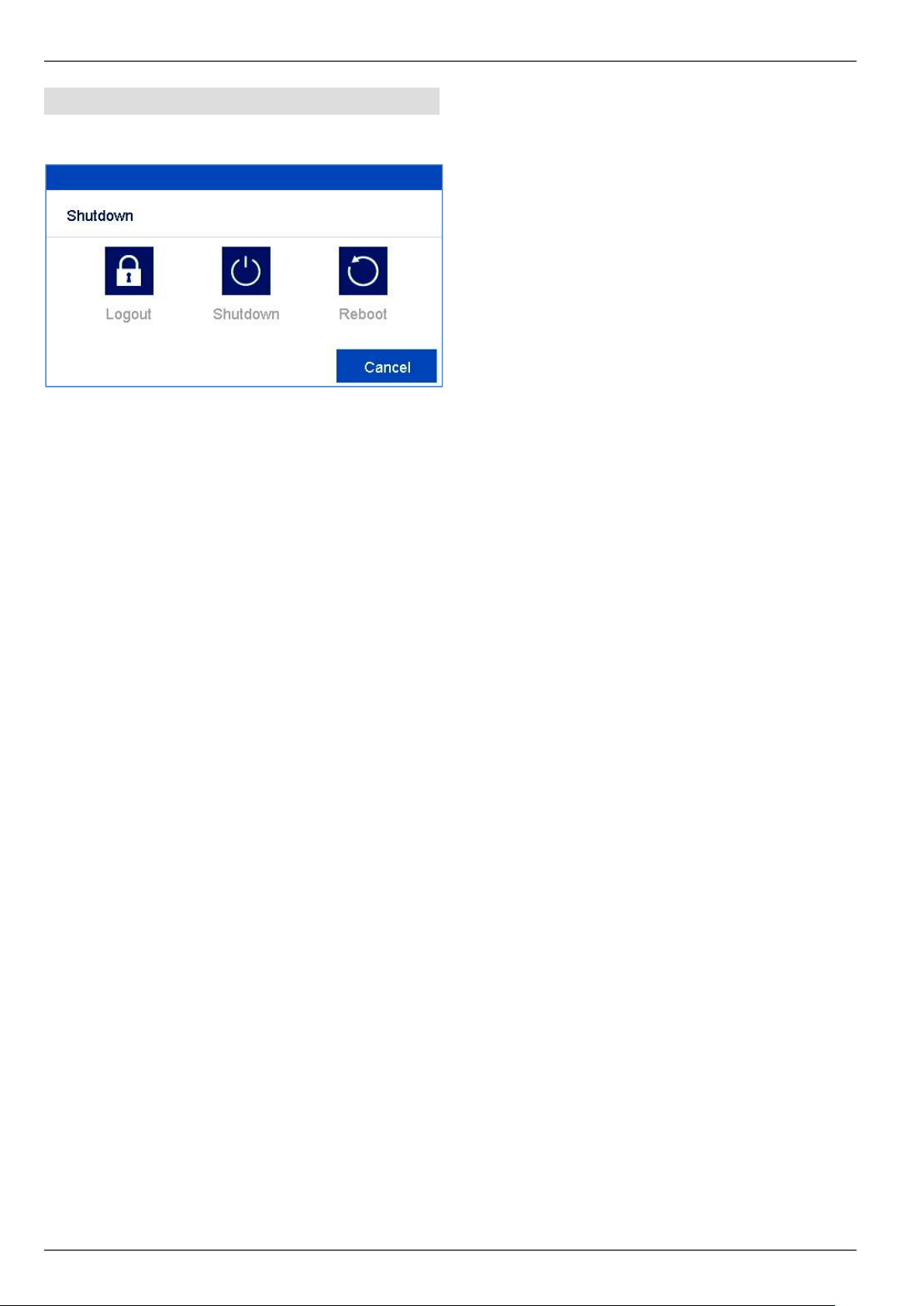
Switching off the device, locking, rebooting
In the main menu, click on Shutdown. The overview
appears.
To switch off, select the Shutdown option and
confirm the query with Yes. The device is switched
off.
Do not press any key during the switch off
procedure.
Now pull out the plug of the power supply unit.
3. To lock the system, select the left hand symbol
Logout. The user interface is locked. To reach the
menu, a password must be entered.
4. To reboot, select the right hand symbol Reboot. The
device carries out a reboot.
16
Page 17
Setup wizard
Setup wizard
Setting up the system
The setup wizard guides you through the required basic
settings for the system. The network video recorder will
then be ready for recording and monitoring.
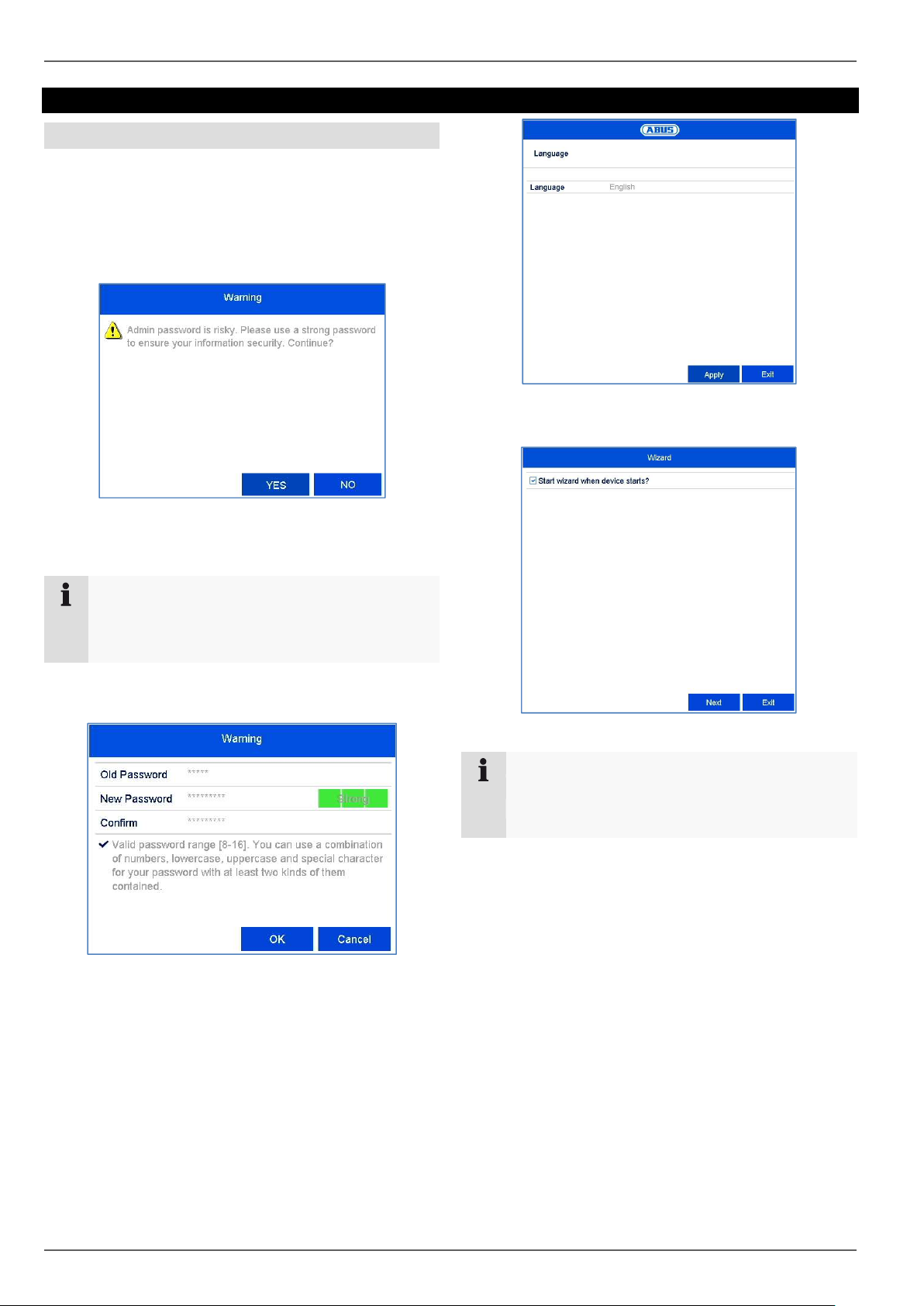
After turning on for the first time, the language selection
appears:
The recorder’s default password is “12345”. This
is a temporary password and must be changed
for security reasons.
Click on the input field and select your language
from the list.
Note
If the password is not changed, a warning notice
will appear until the password has been changed
in line with the security policy.
Change the password immediately by clicking on
“Yes”.
Old password: Enter the default password
New password: Enter a new password, bearing
the security policy in mind.
Confirm the password by entering it again and
clicking OK.
Click on Next to start the wizard.
Note
After the system has been set up the “checkbox”
can be deactivated: the box will be hidden and the
wizard no longer starts automatically.
17
Page 18
Setup wizard
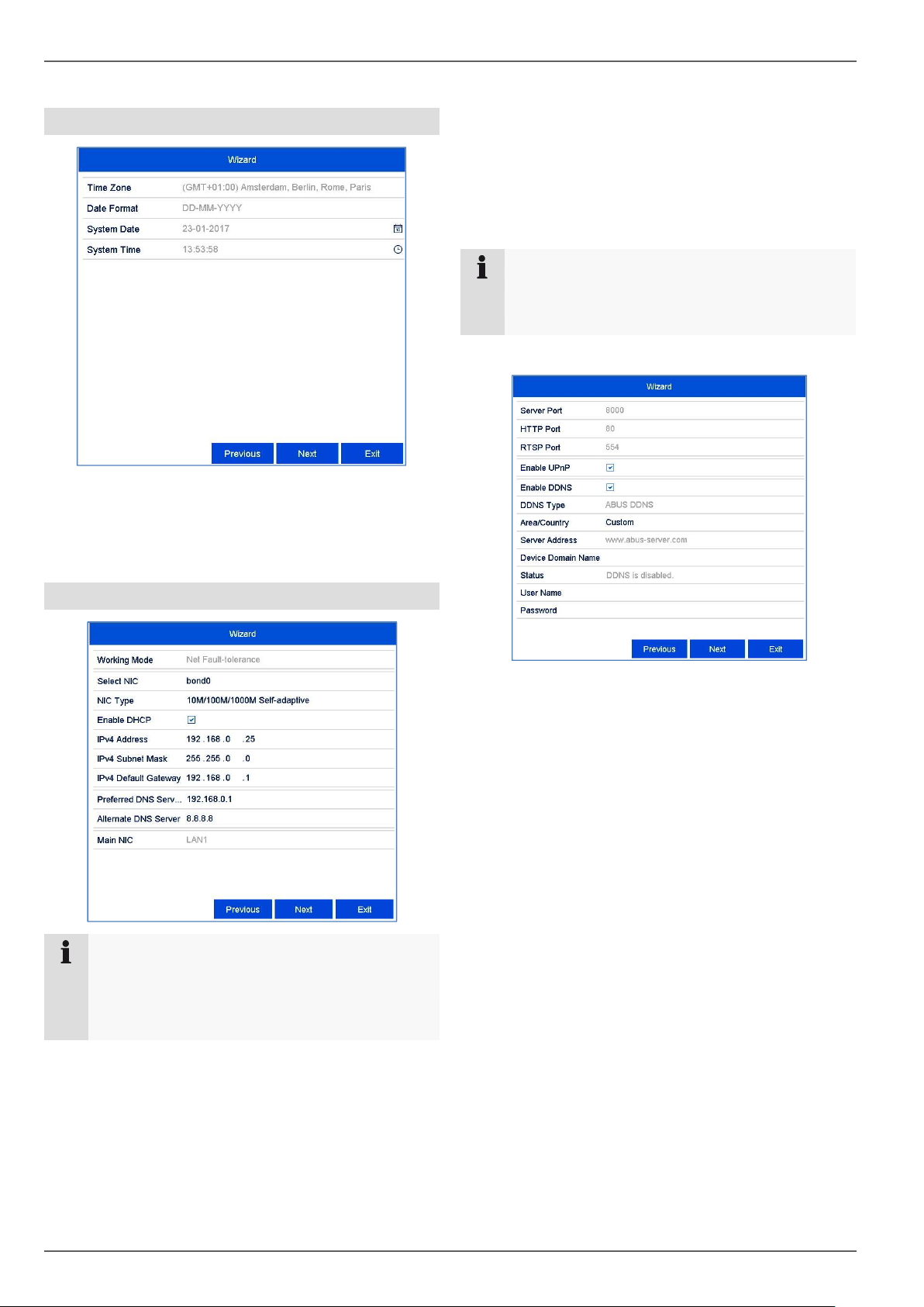
System time and date
Enter the system time consisting of date and
time.
Finish the setting by clicking
on Next.
Network settings
the router, DNS server). A typical address
assignment could appear as follows:
IPv4 address: 192.168.0.50
IPv4 subnet mask: 255.255.255.0
IPv4 default gateway: 192.168.0.1
Preferred DNS server: 192.168.0.1
Note
When the device is accessed remotely via the
internet, it should be given a fixed network
address.
Note
Ask the network administrator responsible
whether the DHCP can be selected or the IP
address and additional settings have to be done
manually.
DHCP active: if the DHCP has been set up in the
network router, enable the DHCP “checkbox”. All
network settings are then completed
automatically.
DHCP inactive: enter the data manually (IPv4
address, IPv4 subnet mask as well as the default
set up for the IPv4 Gateway = IPv4 address of
Adjust the network ports here.
To set up remote access through the internet,
activate DDNS using the “checkbox”.
Click on the input field and select the DDNS type.
When using public DDNS providers, save the
server address and the Device Domain Name,
user name and password.
When using the ABUS server as the DDNS
provider, no extra parameters are necessary.
Click on Next.
18
Page 19
Setup wizard
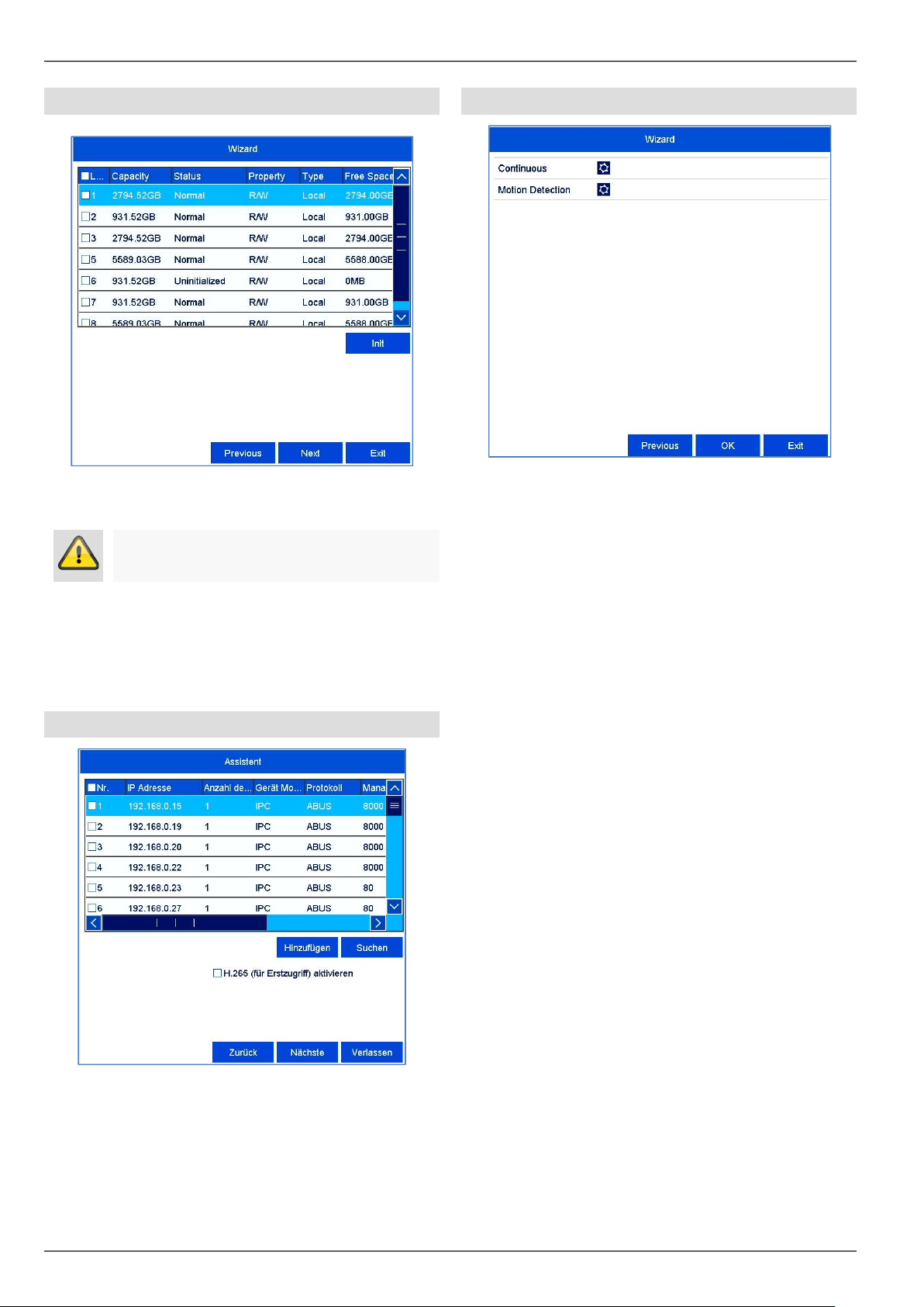
Hard disk drive management
To set up a hard disk drive, enable the “checkbox”
with a left click and then click on Init.
Warning
This will delete all data found on the disc.
Camera recording
Select the recording type. It is possible to select
between "Continuous" and "Movement detection".
Complete the setting and the setup wizard with OK.
Click on OK to acknowledge the security prompt. The
hard disk drive is set up for use. Progress is shown
on the status bar.
Finish the setting with OK and then click on Next.
Camera assistant
Click on Search to display the cameras on your
network.
To add network cameras, activate the desired
cameras and click on Add.
Click on Next to continue with the setup.
19
Page 20
Parameter
Description
Menu bar
Action bar
Right
-
click
Parameter
Description
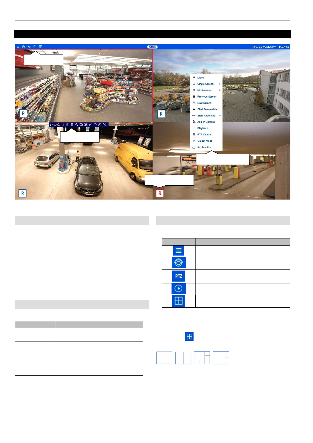
Live view
Menu bar
Live view
Action bar
Right-click menu
General information on live image
Live view starts automatically when the device is
switched on. The live image function provides the option
to display live images and execute camera commands
from all cameras connected to the recorder. Alongside
playback, this is one of the core functions of the recorder.
By double clicking with the left mouse button, you can
display the selected camera image in full screen or
switch back to the original view.
Live image function areas
The live view is divided into the following function areas:
Global display of the configuration
and operating menus.
Control of the camera commands
and actions for the selected
camera (red frame).
Extended operating menu for
menu
operating the live view.
Recording status
Menu bar operation
The following options are available:
Opens the configuration menu
Activates the live image view
(deactivated in the live image)
Switch to the PTZ control menu (only
with PTZ cameras)
Switch to the playback view
Opens multiview
Multiview control
Click on the symbol to open multiview.
Various layouts are available:
Select a suitable layout the live view will be adjusted
accordingly. The settings which define the camera
positions can be individually programmed for each layout
in the configuration menu.
20
Page 21
Live view
Parameter
Description
Camera
Configuration
Special
PTZ
Command
Pre
set
Speed
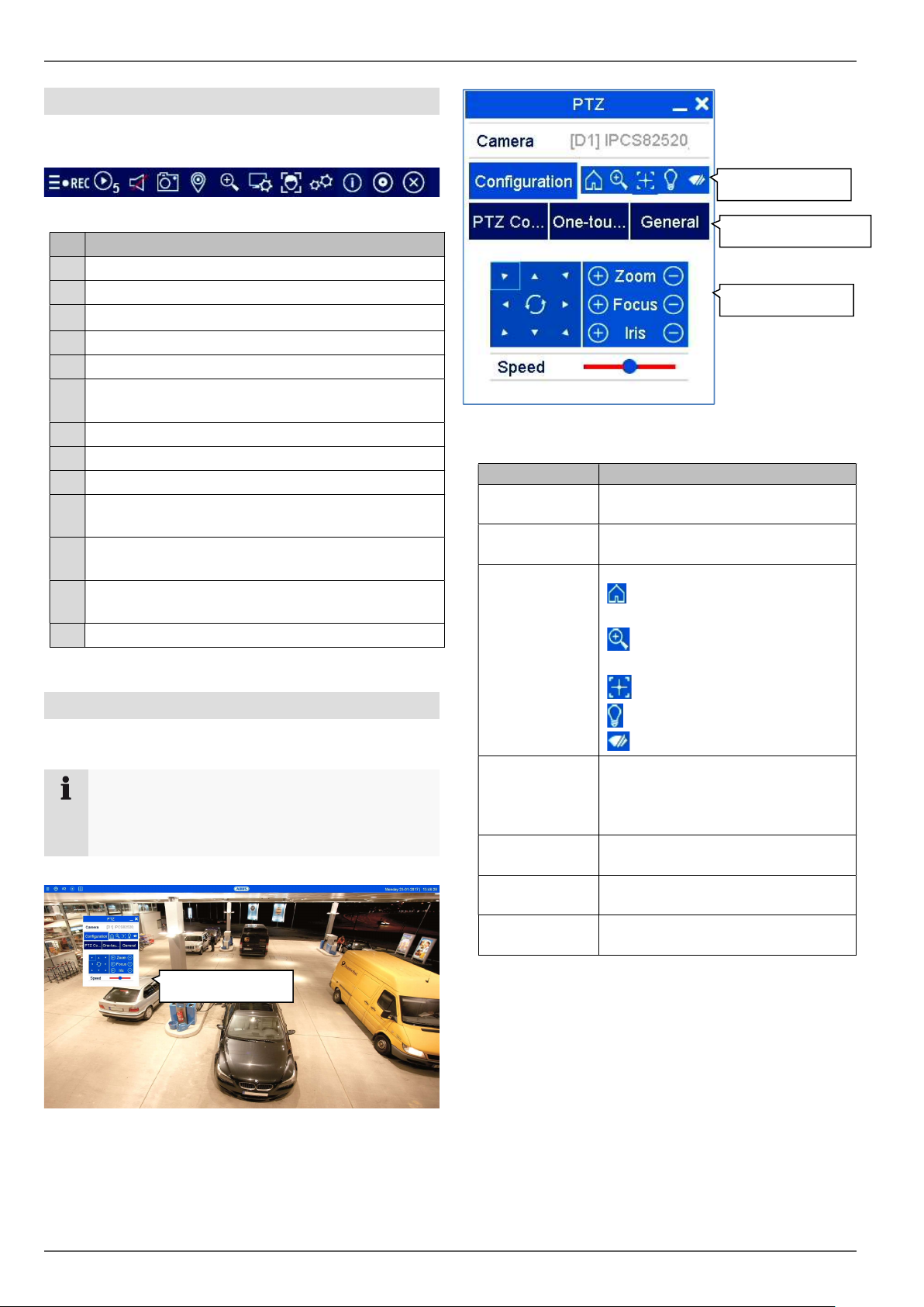
Action bar operation
In single or multi-screen, click on a camera image. A
selection bar will appear:
(0) (1) (2) (3) (4) (5) (6) (7) (8) (9) (10) (11) (12)
Meaning of the symbol
No.
Area for moving the action bar
(0)
Activate/deactivate manual recording
(1)
Instant playback of the last 5 minutes
(2)
Activate/deactivate the audio function
(3)
Create a snapshot from the current camera
(4)
Open the PTZ control menu (for PTZ cameras
(5)
only)
Digital zoom
(6)
Image display settings
(7)
Face detection
(8)
Live view strategy (frame rate control for the live
(9)
view)
Stream information
(10)
(current frame rate, bit rate, resolution)
Activate hemispheric mode (only for hemispheric
(11)
cameras)
Close the selection bar
(12)
The following options are available:
Select the camera for PTZ control
here.
Set the PTZ settings and preset
configuration.
commands
Open camera menu (if
available)
3D zoom (zoom in/out of the
selected mask)
Special
Preset control
PTZ controls
PTZ control menu
The PTZ control menu can be opened from the menu
bar, the action bar or the right-click menu.
Note
The menu can only be opened for PTZ cameras
or cameras with at least one PTZ feature (e.g.:
cameras with a motorised zoom lens).
PTZ control
Centring mode
Light on/off (if available)
Wiper on/off (if available)
PTZ control is displayed. Use the
buttons to turn the camera in the
desired direction and set the
manual zoom, focus and iris.
Execute special commands like
parking position or linear scan.
Execute preset positions, patrols
and patterns.
Speed at which positions will be
manually started.
21
Page 22
Live view
Parameter
Description
No symbol
Recording Status
In live image, the current recording status will always be
shown (below left) in the form of a colourful R (“record”).
Every video channel can have one of the following three
statuses:
No recording programmed
No HDD available
No event
Event recording enabled
(for motion, alarm input or VCA)
Continuous recording enabled
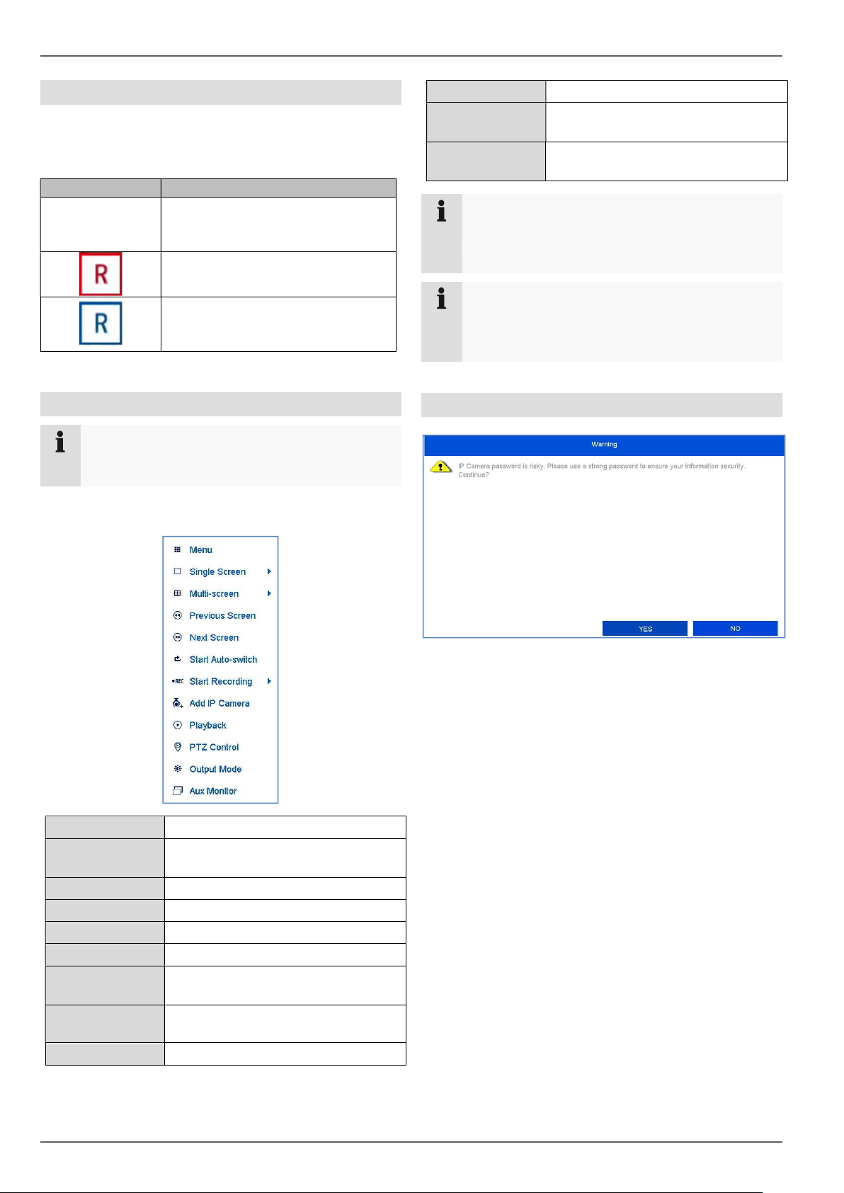
Right-click menu
Note
Right click when the mouse pointer is positioned
on a live image.
PTZ Opens the PTZ control
Monitor mode Sets the output mode for the screen
display
Aux Monitor Switches the mouse control to the
Note
AUX monitor
Start Auto-switch:
Specify the display sequence delay in the display
settings.
Note
Activation of “AUX monitor” without a connected
spot monitor:
Mouse pointer function is disabled.
Password note
The following settings can be made. The arrow pointing
to the right indicates that a sub-menu opens for selection:
Menu Opens the main menu
Full screen Full-screen view of the selected
camera.
Multi-screen Various camera layouts
Previous Screen Displays the previous screen
Next Screen Displays the next screen
Start Auto-switch Starts the camera sequence display
Start Recording Starts continuous recording or
motion detection
Add network
Adds additional network cameras
camera
Playback Switches to playback mode
After every reboot, the recorder displays a warning notice
about the use of weak passwords for network cameras.
This notice appears as long as at least one camera is
using a “weak” password (fewer than 8 characters, no
special characters, no mix of uppercase and lowercase
letters). Change the password of the administrator login
for the network camera according to the security policy:
Password length: 8–16 characters
Combination of lowercase and uppercase letters
Use of special characters
22
Page 23
Playback view
Action
Meaning of the symbol
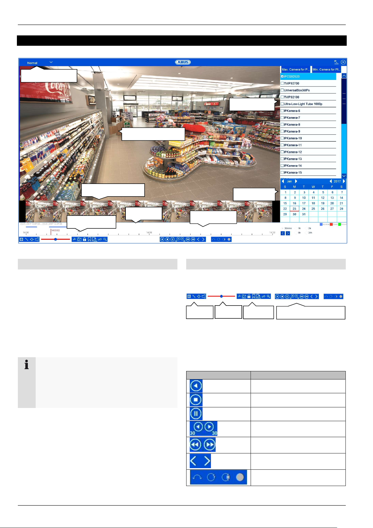
Playback view
Playback type
Camera list
Playback stream
Preview
Time bar
Action bar
General information on playback
There are three different options for playback:
Playback icon in the title bar
Context menu in the live image
Playback function in the overview menu
Playback allows recorded video data from cameras to be
played on the recorder. The data will be played in the
quality with which it was recorded according to the
settings of the network camera.
Note
Adjust the quality settings of the camera
accordingly in the menu under “Settings
Recording Parameters”. In general, the
camera’s “main stream” will be recorded on the
recorder.
The playback view is divided into several functional areas
(playback type) in order to enable a targeted data
analysis (e.g.: event playback, VCA analysis, multitimeshift, etc...). Depending on the selected “Playback
Type”, various operational elements are available in the
playback view.
Calendar
Time tracker
Action bar operation
The action bar is used to control running playback. The
symbols are split into the following categories:
Smart
Audio
Export
Playback
Playback control
The Playback Control is the core element of playback.
The basic functions for the playback of recorded data are
available here.
Reverse playback
Stop playback
Start/pause playback
Go back 30 seconds
Go forward 30 seconds
Slow forward (8x 1x)
Fast forward (1x 8x)
Previous day
Next day
Hemispheric function:
180°/360°/zoom/full screen
23
Page 24
Playback view
Action
Meaning of the symbol
Action
Meaning of the symbol
Action
Meaning of the symbol
Start/stop video clip
Save instant image
Lock data
Add tag
Add custom tag
Open export management
Enable digital zoom
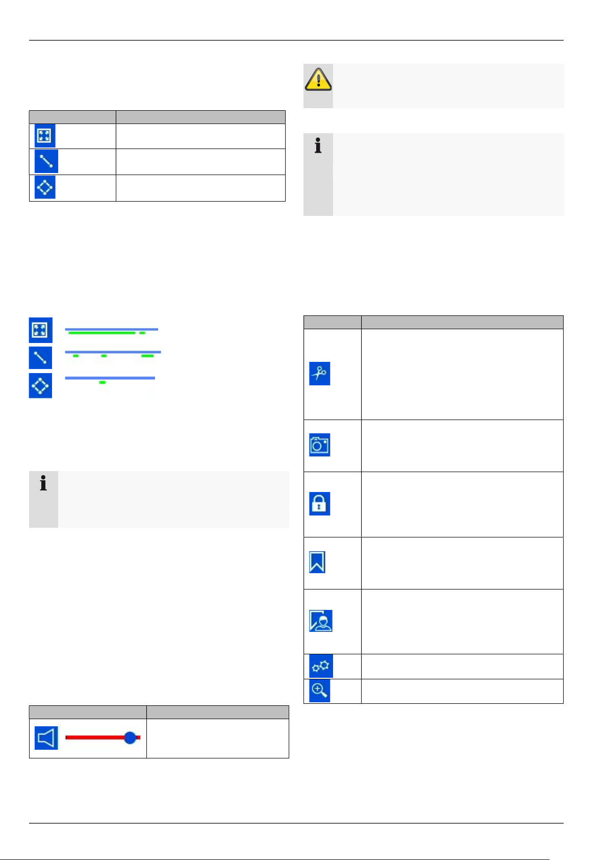
Smart Search
Smart Search makes a fast filter function for the analysis
of recorded data available.
Full screen movement analysis
Tripwire detection search
(set 2 points in the image)
Intrusion detection search
(set 4 points in the image)
Select the desired function and the green filter on the
playback time bar will change accordingly. The following
example offers an overview of the results of the Smart
Search.
Example: Smart Search, same camera, same time
period, different filters.
The motion detection displays many results.
If tripwire is set above the area, fewer events will be
marked already. If intrusion detection is used, only one
event is present in the time period.
Note
Smart Search is not supported by all cameras.
Check the compatibility list at the beginning of
these instructions.
Audio control
Adjust the audio output of the selected camera here. In
the case of multiple selection (2 or more cameras play
back simultaneously), the red tag (red frame around the
camera image) indicates which camera the audio
playback is from. Only one camera’s audio playback can
be played at a time.
Warning
When using audio recording, make sure to
consider the legal requirements for the premises.
Note
In order to enable the audio, the network camera
must be configured accordingly. The following
settings must be activated:
“Menu Recording Parameter Audio &
Video”
Export functions
The following functions describe the possible actions for
the data export from a running playback:
By activating this function, the recorder
notes the current time of the time
tracker.If the tracker is moved by clicking
the mouse and the clip icon is pressed
again, the time segment will be marked
for export.
Saves the currently displayed image
internally on the recorder’s hard disk
drive.
The recording data corresponding to the
current scene (position of the time tracker)
will be locked. A locked data file will not
be overwritten by ring memory.
Creates a tag depending on the position
of the time tracker.Tags can be retrieved
via the playback type “tag”.
Creates a tag with custom text, depending
on the position of the time tracker.Tags
can be retrieved via the playback type
“tag”.
Activates/deactivates the
audio output. Set the volume
using the regulator.
24
Page 25
Playback view
Export type
Description
Tag Meaning
Tag Meaning
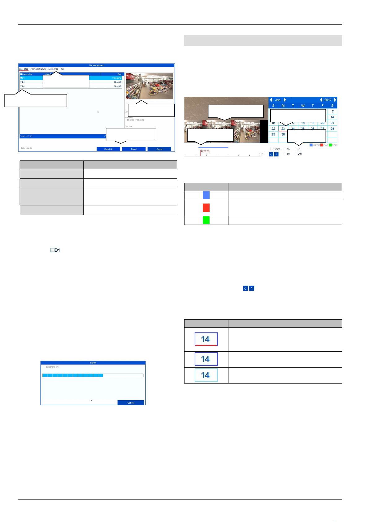
Export management
In export management, tagged playback data can be
exported and managed.
Export type
Export tag
Preview
Start export
Video Clips
Playback Capture
Locked file
Tag
Select an appropriated type from the tab bar. A list with
one or more entries of cameras with data for export (D1–
D32) will appear. Select the desired data by clicking on
the buttons . Select “Export All” to export all of the
displayed list entries, or “Export” to only export the
selected data.
In order to continue the data export, proceed as follows:
1. The data can be exported via USB or the eSATA
interface on the NVR
2. Connect a suitable storage device to the recorder
3. In the next step, select a directory on the storage
device
4. Define whether the video player or the video data
should be exported.
5. The export process is carried out:
Export prepared video clips
Export instant images
Export, manage and unlock
locked files
Tag management
Operation time bar and calendar
The most important operational element of the time bar is
the time tracker. This displays the current time of the
playback. First, move the mouse cursor along the time
bar in order to see a preview of the scene. Then, click on
the time bar to start the playback from the desired time.
Preview
Time tracker
Recordings are shown by coloured bars in the time bar.
The colour coding is as follows:
Continuous recording
Event recording (motion, alarm input,
VCA)
Smart Search (depending on the filter)
The standard setting of the display area on the time bar
is 30 minutes. This means that the last 30 minutes of
recording are displayed across the timeline. In the
Segment section, the timeline can show recordings from
the last hour, 2 hours, 6 hours or 24 hours of the selected
day. You can connect to the camera’s recordings over
the whole day in the increments defined in the segment
settings by using the button.
The days are selected by using the calendar. The colour
coding of the calendar days is as follows:
Currently selected day (red tag).
Current day has at least one recording
(dark blue tag).
Day is not selected, but has recordings
(dark blue tag).
Day is not selected and has no
recordings.
Recordings
Segments
25
Page 26
Playback view
Button
Meaning
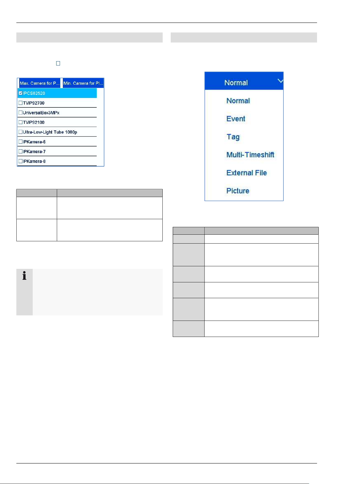
Camera list operation
The camera list enables the selection of the recorded
camera archive on the recorder. By clicking on the
selection fields in the list, any number of cameras can
be played back simultaneously.
The recorder
automatically
activates the
suitable view when
numerous cameras
are selected.
The playback of
cameras which have
been selected
multiple times is
always
synchronous. All
cameras will be played back from the same time (position
of the time tracker).
Max.
cameras for
playback
Min.
cameras for
playback
Note
The NVR manages the camera archives in the
background over the IDs D1–D32. If one camera
is replaced by another on the same channel ID,
the data recorded up to that point remains
unchanged on this channel.
All available camera archives will be
selected.
Only the first camera will be selected
for playback.
Selecting playback type
Selecting the playback type allows various types of
recording and events to be displayed and filtered in the
playback view.
The following menus are available:
Type Description
Duration
Event
Tag
MultiTimeshift
External
File
Image
Playback of recorded video data.
Search and playback of video data
recorded by means of motion detection,
VCA or alarm input.
Search and playback of video data which
has been provided with a tag.
Simultaneous playback of video data from
one camera at different times.
Search and playback of video data found
on a connected external data storage
device (USB).
Playback of saved snapshots with date
and camera filter.
26
Page 27
Playback view
Filters
Description
Filters
Description
Filters
Description
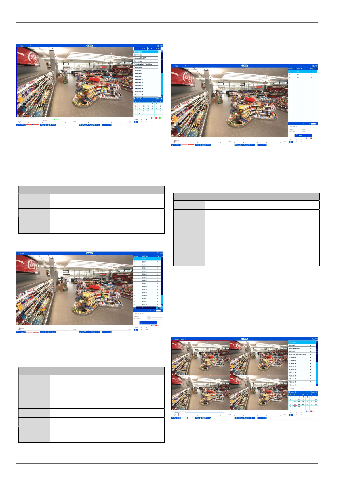
Playback: Normal
“Normal” playback is the default view always displayed
when the playback function is opened.
Using this view, all recorded data can be quickly
displayed and analysed. The time bar distinguishes
between continuous recording and event recording
(motion, alarm, VCA).
Camera
channels
Calendar
Time bar
Select one or more camera channels.
Select a date for playback.
Select a playback time on the timeline
using the mouse.
Playback: Event
Select an entry from the list of results and start playback
by clicking on the appropriate icon.
Playback: Tag
Using “Tag” playback, the recordings can be searched
using pre-defined tags. This requires tags to have been
created beforehand by the user.
There are other filters available for the search:
Cameras
Keyword
Start time
End time
Search
Select an entry from the list of results and start playback
by clicking on the appropriate icon.
Select one or more camera channels.
You have the option of entering a keyword
as a full text filter for the search. If no
keyword is specified, all tags are searched.
Select the start date and start time.
Select the end date and end time.
Start the tag search using the previously
defined filters.
Using “Event” playback, event recordings can be
searched in a targeted way. There are other filters
available for the search:
Filter1
Filter2
Cameras
Start time
End time
Search
27
Select an event type: motion, alarm, VCA
Select a VCA type: all, Tripwire, Intrusion
Detection, Face Detection.
Select one or more camera channels.
Select the start date and start time.
Select the end date and end time.
Start the event search using the previously
defined filters.
Playback: Multi-Timeshift
Using “Multi-Timeshift” playback, different points in time
from one single camera channel can be simultaneously
analysed in a targeted way. To do this, the channel is
Page 28
Playback view
Filters
Description
Filters
Description
Filters
Description
played back with a time delay of up to 16x, according to
the setting.
There are other filters available for the search:
Camera
Segments
Clicking on a segment displays the time range as the top
line within the timeline.
Select a camera channel.
Select the number of segments
for simultaneous playback. The
more segments selected, the
shorter the time interval from
one segment to the next during
playback. The division of the
segment is as follows:
Duration of recording per
day/number of segments = time
interval per segment.
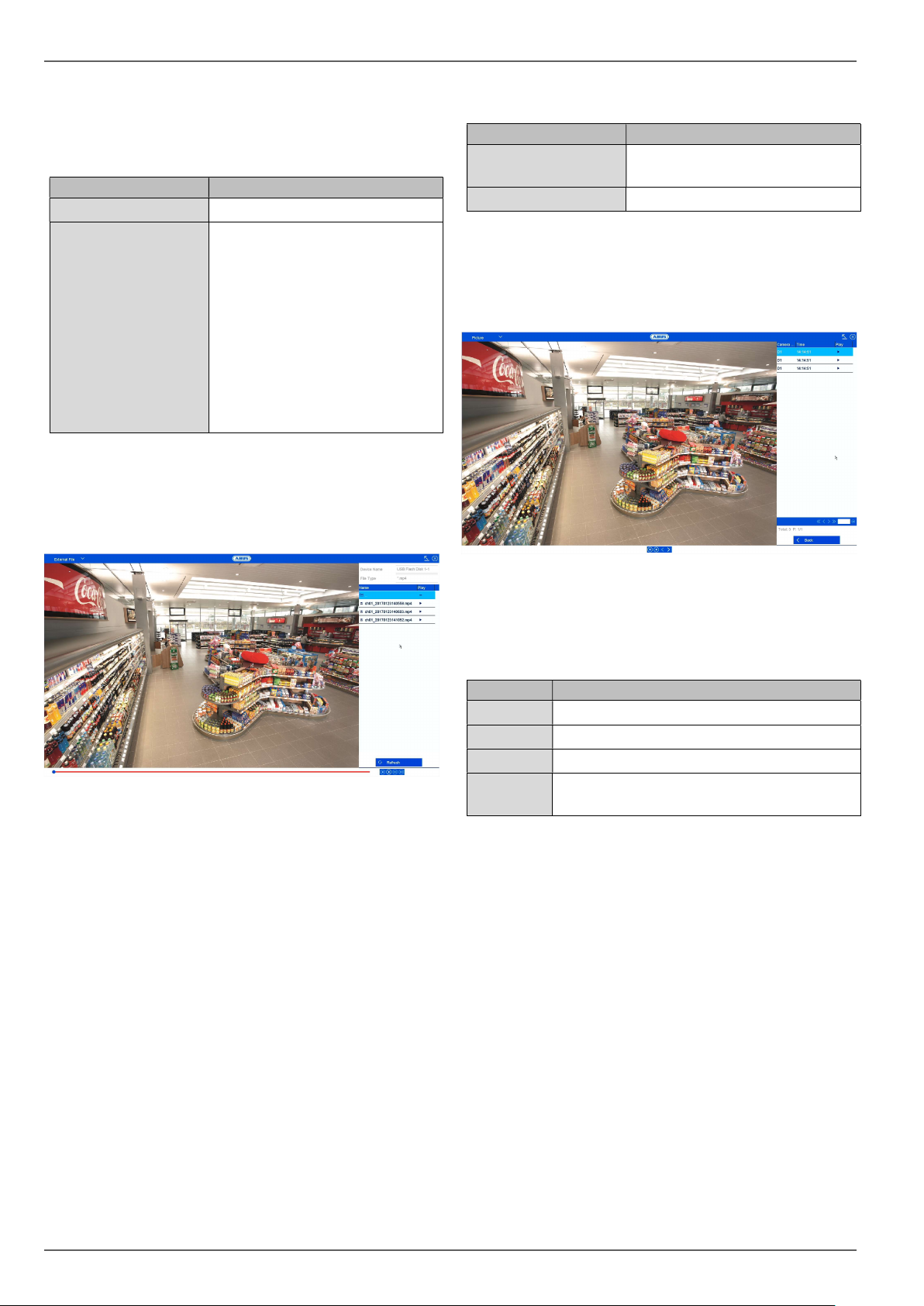
Playback: External File
There are other filters available for the search:
Device Name
File Type
Select an entry from the list of results and start playback
by clicking on the appropriate icon.
Select a USB data storage
device from the list.
Select a file type from the list.
Playback: Image
Using “Image” playback, images saved internally on the
NVR (saved via the snapshot function from the live view,
playback or via time schedule) can be played back.
There are other filters available for the search:
Using “External File” playback, previously exported video
clips and images from external data storage devices can
be played back.
Cameras
Start time
End time
Search
Select an entry from the list of results and start playback
by clicking on the appropriate icon.
Select one or more camera channels.
Select the start date and start time.
Select the end date and end time.
Start the tag search using the previously
defined filters.
28
Page 29
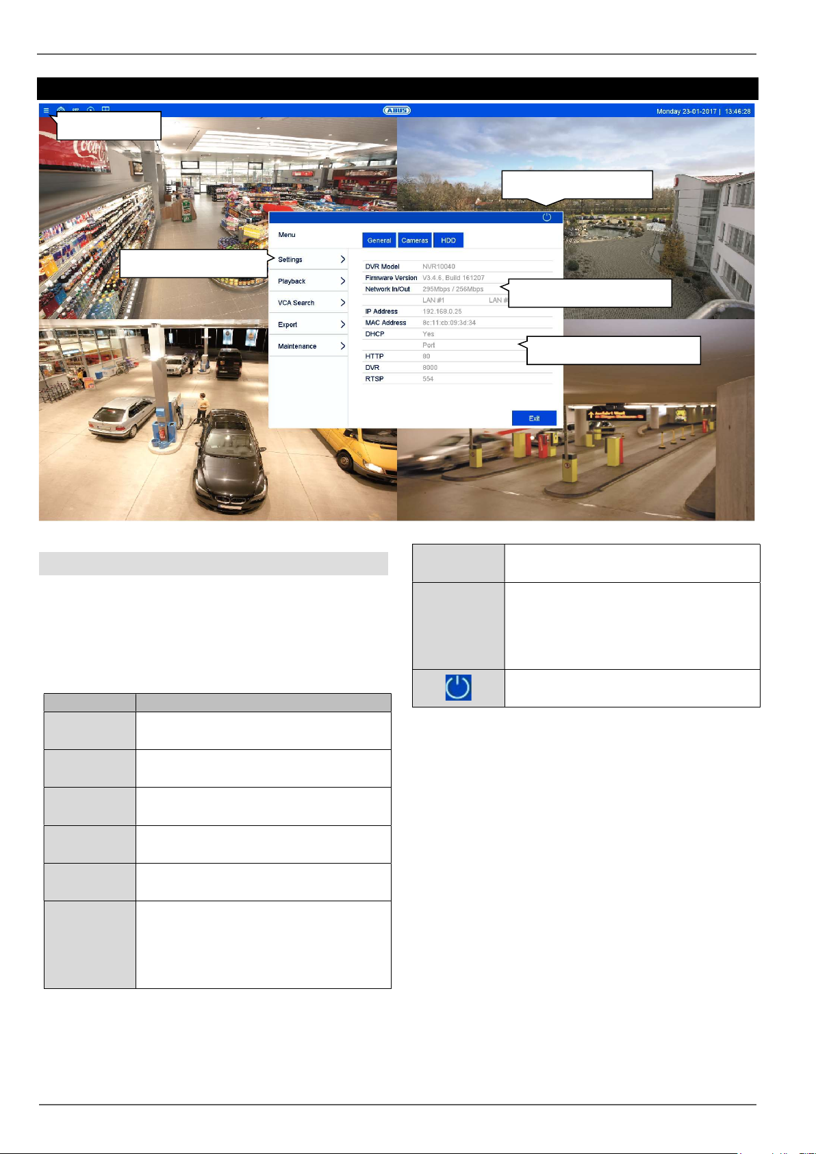
Info menu
Menu
Description
Info menu
Open menu
Logout/switch off
System
Available bandwidth
Network information
General information menu
The info menu is an upstream status menu which
provides a quick overview of the important system
parameters and settings. From here, further actions can
be carried out and the system configuration can be
performed. The following options are available:
General
Cameras
HDD
Settings
Playback
VCA search
Status overview of network capacity and
network configuration.
Status overview of cameras and
recording.
Status overview of hard disk drives and
memory capacity.
Leads to the Configuration, Camera,
Recording, HDD and Manual menus.
Opens the playback view (see
“Playback view” section).
Parameter-controlled search for video
and image recordings triggered by
events such as tripwire detection, as
well as analysis of face search and
people counting.
Export
Maintenance
Click on “Exit” to close the info menu.
The following chapter describes the following sections:
Export of video and image recordings to
external data storage devices.
System information, searching logs,
importing/exporting configurations,
device maintenance such as upgrading
to new firmware, loading defaults,
displaying traffic.
User logout, system shutdown or
system reboot.
Settings
VCA search
Export
Maintenance
29
Page 30
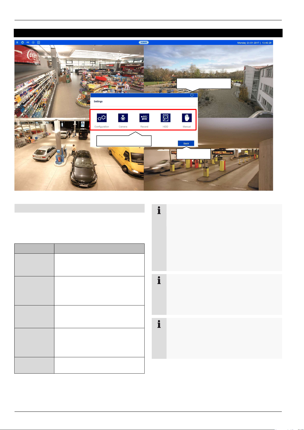
Settings
Settings
Logout/switch off
System
Info menu
General information on settings
System configuration of the recorder can be carried out in
the “Settings” menu. The settings dialogues are split into
the following categories:
Menu Description
Configuration Used to manage all device settings
(General, Network, Live View,
Warning and User).
Camera Menu for setting camera parameters
(OSD configuration, image mode,
motion detection, private zone,
tamper monitoring and video loss).
Recording Menu for setting recording
parameters (schedule, camera
resolution, holiday etc.)
HDD Used to initialise and manage a built-
in hard disk drive (assign read/write
functionality, cameras, manage
network drive etc.)
Panic
Recording
Menu for setting manual recordings.
Note
Depending on your recorder model, all of the
functions described in the guide may not be
available for your model (e.g.: RAID).
Later firmware updates may add new functions or
expand settings to include further parameters.
The valid firmware version number to which this
guide makes reference can be found on the cover
page of the guide.
Note
The system configuration can also be performed
via remote applications (e.g.: web interface or
CMS software). Normally, the same functions are
available there. If not described further, then this
guide may be used as a reference.
Note
Camera-specific functions are only explained as
examples within the scope of recorder-relevant
setting options. Further details on these functions
can be found in the camera user guide (e.g.:
operating tripwire detection).
30
Page 31

Setting: Configuration
Live
Submenu “tab”
Setting: Configuration
General information on configuration
The configuration menu is used to manage all basic
device settings. During the initial commissioning,
complete the settings in this section first.
Warning
Ensure that the date and time are set correctly.
IMPORTANT: Subsequent alterations may lead to
loss of data.Ensure data is backed up beforehand.
The configuration menu is divided into the following
sections:
Menu Setting
General Language, video, time, date,
mouse, password, daylight saving
time and other settings.
Network Required network settings (manual
IP, DHCP, PPPOE, DDNS etc.) and
overview of network status.
Save
Exceptions Response of the device in
exceptional cases (hard disk drive
full, network disconnected etc.)
User Adding and changing users and
assigning access rights.
Hot spare Setting up the back-up function in
the event of device failure.
Every menu item has further submenus (e.g.: DST
settings) which are hereinafter referred to as “tabs”.
Confirm changes to settings in the detail settings of the
tabs by pressing the “Apply” button.
Use the icon to switch directly to the live view in order
to review settings which have a direct effect on the live
image functions.
RS-232 Settings for the serial interface (for
servicing purposes only).
Alarm Settings for the alarm I/Os for the IP
cameras.
Live view Display settings and assignment of
the event output.
31
Page 32

Setting: Configuration
General
The general display configuration settings and date
settings can be found here.
General tab
General Setting
Language On-screen display language
VGA Resolution Monitor resolution of the VGA
output
HDMI Resolution Monitor resolution of the HDMI
output
Time Zone GMT (Greenwich Mean Time).
Date Format MM-DD-YYYY, DD-MM-YYYY,
YYYY-MM-DD
Date Set date
Time Set time
Mouse Pointer
Speed
Enable Wizard Box ticked:
Enable Password Box not ticked:
Slider (left = low speed,
right = high speed)
The wizard will appear when the
system is started up.
A password does not need to be
entered into the recorder itself.
However, the password does need
to be entered if accessing via the
network.
Box ticked:
The password needs to be
entered in order to use the menu.
DST Settings tab
DST settings Setting
Auto DST
Adjustment
Enable DST If the box is ticked, a specific start/end
From/to Start/end date for daylight saving time
DST Bias Daylight Saving Time bias: correction
If the box is ticked, the device
switches automatically to daylight
saving time.
date can be selected.
of daylight saving time to reference
time
More Settings tab
More settings Settings
Device Name Name of recorder
No. Used for unique identification when
using CMS software.
Auto Logout Never/1–30 minutes: controls how
long the menu is displayed before it is
hidden again
Menu Output
Mode
Use to specify the monitor output for
the menu display. If set to auto, the
recorder will detect the output.
32
Page 33

spensable for connecting network cameras and
In certain modes some of these settings cannot be
Setting: Configuration
Network
The complete network configuration of the recorder can
be carried out in the “Network” menu. The recorder must
be physically connected to the network via at least a
CAT5 cable. To allow for smooth network operation, we
suggest using continuous gigabit cabling between the
recorder, camera and switch.
Note
Having the correct network settings is
indi
accessing the recorder via remote software
(browser, CMS, app).
Warning
When using a router, the network clients, and
therefore the recorder, are “connected” to the
internet and vice versa.
You should make sure that you take protective
measures, such as using a firewall, changing your
password and changing the port, to prevent
unauthorised external access.
General Setting
NIC type Set the transmission speed of the
integrated network card here.
Select “Self-adaptive” so that the
recorder can automatically determine
the best possible speed.
DHCP Tick the box if the IP addresses on the
network are assigned dynamically via
DHCP.
DHCP enabled: subsequent entry fields
are set to disabled because parameters
are obtained via DHCP.
Note:
If the IP addresses are assigned
manually, ensure that DCHP is not
enabled (do not tick the box).
IPv4 address Address of the network device on the
network when assigned manually
IPv4
Usually 255.255.255.0.
Subnet Mask
IPv4 Default
Gateway address for internet access
Gateway
IPv6 Address 1 Local (link local) IPv6 address
General tab
Settings for the local network and selecting the network
mode are defined here.
IPv6 Address 2 Global (global unicast) IPv6 address
IPv6
Standard
IPv6 gateway address for internet
access
Gateway
MAC
address
Hardware address of the integrated
network card
MTU(Bytes) Describes the maximum protocol packet
size.
Preferred
DNS server
Alternative
DNS server
Address of the domain name server,
usually the IP address of the gateway.
IP address of the alternative DNS
server
Note
selected.
33
Page 34

Setting: Configuration
DDNS tab
The DDNS function is used to update host names and
DNS entries.
DDNS Setting
Enable
DDNS
DDNS type Select the DDNS service provider.
Region/count
ry
Server
address
Device
domain
name
Status Display of the DDNS status
User name Enter the user name of your DDNS
Password Enter the password for your DDNS
If you want to use the ABUS server for remote access,
proceed as follows:
1. To be able to use the ABUS DDNS function, you first
need to set up an account at www.abus-server.com.
Please read the FAQs on this topic on the website.
2. Tick the “Enable DDNS” box. Then select “ABUS
DDNS” as the DDNS type and enter the www.abus-
server.com host name in the “Server Address” field.
3. Apply the data by clicking on Apply. The IP address
of your internet connection is now updated with the
server.
Activates the DDNS synchronisation.
If necessary, select a region/country.
Enter the IP address or host name of
the DDNS provider.
If necessary, enter the sub domain of
the device.
account.
account.
NTP tab
The Network Time Protocol automatically synchronises
the time via the network.
NTP Setting
Enable NTP Activates the NTP function on the
recorder
Interval
(min.)
NTP server NTP server address
NPT port NPT port
Note
The recorder can synchronise the time with an
external server. Several server addresses are
available on the internet for this purpose.
1. Tick the “Enable NTP” box and enter the interval
after which synchronisation should be repeated.
Enter the IP address of the NTP server and the NTP
port.
2. Apply the data by clicking on Apply.
Determines the interval for
synchronisation.
Email tab
In the event of an alarm, the device can send a message
by email. Enter the email configuration here.
34
Page 35

Setting: Configuration
Email Setting
Enable Server
Authentication
User name Email account with the provider
Password Password used to protect the email
SMTP Server SMTP server address of the provider
SMTP Port Enter the SMTP port
Enable SSL Tick the box to enable email
Sender Name of the sender
Sender’s
address
Select
Receivers
Receiver Enter the name of the recipient here
Receiver's
address
Enable attached
picture
Interval Select a trigger time of between two
1. Enter the parameters of the email notification.
2. Then click on Test to send a test email.
3. If you have entered everything correctly and have
received a confirmation email, click on Apply.
Tick the box when logged onto the
internet provider’s server
account
(default: 25)
encryption
The email address linked to the
email account
Select three potential recipients for
the email
Enter the email address of the
recipient
Tick the box if camera recordings
should also be sent with the email as
photo files
and five seconds. The pictures will
only be sent if motion is detected
during the time frame defined.
SNMP tab
SNMP is a protocol for displaying the network status via
corresponding SNMP software.
SNMP Setting
Enable SNMP Select the checkbox to create a
connection to SNMP software
SNMP Version The version of the SNMP system
SNMP Port
Read Community Enter the “Key” according to the
Write Community Enter the “Key” according to the
Trap Address Enter the IP address for the SNMP
Trap Port Enter the trap port (default: 162)
Enter the SNMP port
(default: 161)
settings of your SNMP software.
settings of your SNMP software.
manager
Note
SNMP is used for monitoring the device status.
For this you need suitable SNMP software.
35
Note
The device will send an email to the specified
recipients.
If no email is received, check the settings and
correct them where necessary. If necessary,
check the junk mail settings of your email client.
Note
You can obtain the access data and settings for
sending SMTP from your email provider. Some
email providers only provide SSL encryption for
sending emails. This recorder has been tested for
SSL compatibility with the following providers:
GMX, Web.de and Gmail.
NAT TAB
Network Address Translation is for the separation of
internal and external networks.
Page 36

Setting: Configuration
NAT Setting
Enable UPnP™ Tick the box to enable visibility on an
IP network. When this function is
enabled, port forwarding is
automatically entered in the router for
all network ports (provided that UPnP
is enabled in the router).
If UPnP is enabled, the network ports
configured by UPnP are transferred
to the ABUS server (provided that
ABUS DDNS is enabled).
Mapping Type For “manual” settings, the network
ports can be manually defined using
the “Edit” button.
For “auto” settings, the recorder
checks for free network ports on the
router and defines the port numbers
in a random pattern.
More Settings tab
Note
Server port 8000 is used for remote
communication
via iDVR Plus/iDVR Plus HD and ABUS CMS.
HTTP port 80 and RTSP port 554 are used for
remote access to the web interface.
Used to configure the IP address of the PC where a
notification should be displayed in the event of an alarm.
More settings Setting
Alarm Host IP Network address of the CMS station
Alarm host port Port for your CMS station
(default: 7200)
Server port Port for data communication
(default: 8000)
HTTP port Port for the web server
(default: 80)
Multicast IP You can enter the multicast IP here
too in order to minimise traffic. The IP
address must correspond to the one
in the video surveillance software.
RTSP port Enter the RTSP port
(default: 554)
36
Page 37

Setting: Configuration
Alarm
Configure the behaviour of the recorder’s physical and
virtual alarm inputs and outputs in the alarm menu.
Alarm Status tab
Here you can see a list of all the alarm inputs and outputs
and their current status.
Alarm input Setting
Localxx Shows the status of alarm input “xx”.
The numbering “xx” corresponds to
the numbering of the physical alarm
inputs (1–16).
192.168.1.5:80
00 xx
Alarm name Name (if assigned) of the alarm input.
Alarm type N.O.: normally open circuit
Alarm output Setting
Local xx Shows the status of alarm output “xx”.
192.168.1.5:80
00 xx
Alarm name Name (if assigned) of the alarm
Dwell Time States how long (in seconds) the
Shows the status of the alarm input
for IP address 192.168.1.5 “xx”. The
numbering “xx” corresponds to the
numbering of the camera’s physical
alarm inputs (1–8).
N.C.: normally closed circuit
The numbering “xx” corresponds to
the numbering of the physical alarm
outputs (1–8).
Shows the status of the alarm output
for IP address 192.168.1.5 “xx”. The
numbering “xx” corresponds to the
numbering of the camera’s physical
alarm outputs (1–4).
output.
relay is closed when activated.
Alarm Input tab
Linkage action
Copy
Configuration of individual alarm inputs
Parameter Setting
Alarm input Select the alarm input to adjust the
Alarm Name Enter a clear description, e.g.
Type N.O.: normally open circuit
Arming Activates/deactivates the selected
Settings Define the linkage action.
Activate the alarm input by ticking the “Activate” box.
Define the response of the recorder in the event of an
alarm under "Settings".
Click on Copy to apply these settings to other alarm
inputs.
Confirm the settings by clicking on Apply and exit the
menu by clicking on Back.
Further settings for the programming of an action/time
schedule for alarm inputs and outputs are described in
the “Linkage Action” section.
settings. You can select the alarm
input for an IP camera using the
network address data.
warehouse door contact.
N.C.: normally closed circuit
alarm input.
Alarm output tab
37
Configuration of individual alarm outputs
Page 38

Setting: Configuration
Parameter Setting
Alarm output Select the alarm output to adjust the
settings. You can select the alarm
output for a network camera using
the network address data.
Alarm name Enter a clear description, e.g.
warehouse door contact
Dwell Time Select the dwell time for switching
the alarm output.
Settings Define the linkage action.
Activate the alarm output by ticking the "Settings"
box.
Define the schedule for the recorder alarm output in
the event of an alarm under "Settings".
Linkage action
The “Linkage action” menu is the recorder’s central event
control function. From here, event-based recording, time
schedules, emails, acoustic warnings, CMS notifications
and PTZ actions can be programmed.
Linkage actions are available in various menus on the
recorder (e.g.: alarm, motion detection, VCA).
Note
If not further defined, use this section as a
reference for the configuration of Linkage Action
and as a substitution for all relevant menus in the
recorder.
Trigger channel tab
Tick the corresponding box to select which camera
channel is triggered in the event of an alarm.
Parameter Setting
Trigger
channel
Arming
schedule
Select which camera should be
triggered in case of an alarm/incident.
A trigger signal normally causes an
alarm recording.
If you wish, you can decide whether
the schedule of a camera should be
activated in the event of an incident.
This setting is only practical if the time
schedule of a camera was explicitly
deactivated beforehand (see
“Recordings” menu). Normally, the
time schedule of a camera is always
enabled.
Arming Schedule tab
Set the time at which the responses selected on the
“Linkage Action” tab are activated when there is an
alarm.
Click on “Copy” to apply these settings to other days
of the week or the entire week.
38
Page 39

Setting: Configuration
Linkage action tab
Select the Linkage action tab.Here. you can configure the
response of the recorder in the event of an alarm by ticking
the corresponding box. All actions can be enabled
simultaneously.
Parameter Notifications
Full Screen Monitoring The camera is displayed in
full screen in live view.
Audible Warning The recorder emits a
repeated signal tone.
Notify CMS A notification will be sent by
network command to the
CMS software.
Send email An email is sent to a
specified email address.
Trigger alarm output The selected alarm output is
triggered in the event of an
alarm.
Parameter Notifications
PTZ Select the camera to be
controlled using a PTZ
command in the event of an
alarm.
Call preset Select the preset number.
Start patrol Select the patrol number.
Start pattern Select the pattern number.
Confirm the settings by clicking on Apply and exit
the menu by clicking on OK.
RS-232
The “RS-232” menu is only used by ABUS SecurityCenter for service purposes.
Live view
In the live view menu, define the behaviour of the local
image output on the recorder. This includes the basic
settings for the menu display and the configuration of the
cameras' image distribution in multi-view.
General tab
PTZ linking tab
Here you can control specific PTZ presets, patrols or
patterns for a taught-in camera.
39
The following settings are available in the General tab:
Video Output
Interface
Live View
Mode
Dwell Time Switching time between the
Enable Audio
Output
VGA/HDMI
Select the connection where the
settings are changed.
Various camera layouts
1x1, 2x2, 1+5, 1+7, 3x3, etc.
individual cameras during autoswitch.
Activates the audio output for the
live view.
VGA: if this option is selected, the
audio output takes place via the
cinch sockets on the back of the
recorder
Page 40

Setting: Configuration
displayed
Connect the VGA cable and restart the recorder to
HDMI: if this option is selected, the
audio output takes place via the
HDMI interface.
Display
Activate/deactivate the status bar.
status bar
Volume Adjust volume
Event
output
Full Screen
Monitoring Dwell
Time
Post-Event
Display Time
Allocate monitor for the output of
events.
The number of seconds for which
the event will be displayed on the
allocated monitor.
The number of seconds for which
the pop-up window should be
displayed in the event of an alarm.
Note
VGA monitor connected:
If a VGA monitor is connected, it will be
recognised automatically when the device is
started up. The main video signal will be
on the monitor.
No HDMI monitor connected:
If no HDMI cable is connected to the monitor
when the device is started up, the main video
signal will be emitted at the VGA connection.
perform automatic detection.
View tab
1. Click on the View tab
2. Select a view mode from
3. Use the navigation keys to allocate the required
camera signal to the corresponding screen
section.
4. Click on Apply to apply the setting.
Symbol Meaning
Select
multi-view:
1x1, 2x2, 5+1, 7+1, 3x3,..
Assign all available
cameras to the current view
in sequence (D1, D2, ...).
Remove all cameras from
the current view.
Next/previous page. If more
cameras are assigned than
the amount of available
spaces in the view, an
additional page will be
created.
The mouse scroll wheel can
be used to move between
pages in the live view.
Exceptions
You can display up to 36 cameras simultaneously in live
view.
Note
Watch out for possible limitations in the live view
with regards to the local decoding power of the
recorder.
Set the response of the recorder for warning messages
and system events here. To do this, activate the “Enable
event hint” setting.
You can trigger a warning for the following error types:
HDD Full
HDD Error
Network Disconnected
IP Conflicted
Illegal Login
Exception Error
40
Page 41

Setting: Configuration
The event hints are either acoustic or sent by email and
are additionally displayed in the live image view.
Parameter Notifications
Audible Warning The device emits a repeated
signal tone.
Notify CMS A notification is sent to the
CMS software event log.
Send email An email is sent to a
specified email address.
Trigger alarm output The selected alarm output is
switched in the event of a
fault.
Event display
In the menu item “Event hint settings”, enable the events
for display in the live image view. In the default settings,
all events are displayed in the live image view.
User
To add a new user, select
Add. To edit an existing user, select the pen icon.
Parameter Setting
User name Unique identification
Password Access code for the device, for the
purpose of device management
Note: change your passwords
regularly, using a combination of
letters and numbers etc. and note
them down to be stored in a safe
place.
Confirm Enter the access code again for
security
Level Select the user’s authorisation level.
IMPORTANT:
More rights can be set on the
Operator level than on the Guest
level.
User's MAC
Address
MAC address of the network adapter
of the PC used by the corresponding
user
Note:
This limits access to the PC, for which
the MAC address has been entered
here.
In user management, you can add new users, delete
users, and amend existing settings.
Warning
Change the default password during the initial
commissioning to ensure secure operation.
41
Control the access permission of the user by clicking on
the “Permission” icon. Only the access data of users
added manually can be changed.
Page 42

Setting: Configuration
Local configuration tab
The permissions in the “Local configuration” tab are
related exclusively to configuration settings which are
accessible via the local user interface (access via local
monitor).
Remote configuration tab
Camera configuration tab
The permissions in the “Camera configuration” tab are
related exclusively to cameras. Here, the access and
operation of cameras (live/playback/export) are controlled
remotely and locally.
Hot spare
The permissions in the “Remote Configuration” tab are
related exclusively to configuration settings which are
made accessible/blocked via remote applications
(browser, app, CMS software). If a permission is
withdrawn, this generates a corresponding error
notification in the remote application (e.g.: changes to
camera settings via CMS).
Hot spare mode offers an additional safeguard against
the failure of your recording system. At least one
additional recorder is needed for this.
Note
When hot spare mode is enabled, the usability of
the recorder is limited. Only basic configurations
are available in the Settings menu.
The primary recorder performs the “master” function for
recording, camera configuration and live image display. If
the primary recorder stops working (power failure,
network failure), the hot spare recorder automatically
takes over (live display and recording).
Once the primary recorder is back in operation, the hot
spare recorder transfers all the data back to the primary
recorder and goes into standby mode.
42
Page 43

Setting: Configuration
Note
The hot spare recorder permanently synchronises
its camera and recording settings with the primary
recorder in order to operate with identical settings
in the event that the primary recorder stops
working.
Please ensure that both devices are connected to your
network. If this is not the case, please set them up as
described in the chapter “Network Configuration”.
Setting up hot spare mode
1. First, set up the second device on the network and
configure all basic functions (date, memory drives
etc.).
2. In the “Hot spare” menu, select the hot spare mode
for this device. You will need to restart the recorder in
order to do this. Follow the instructions.
3. Make a note of the IP address for the hot spare
device.
4. Switch to the “Hot spare” menu in your primary
recorder as well, select the “Normal mode” option
and enable the function.
5. Enter the IP address and password for the hot spare
device.
6. A permanent connection is now established between
the primary device and the hot spare device.
7. Setup is now complete.
To apply the settings, confirm your selections by clicking
on Apply.
43
Page 44
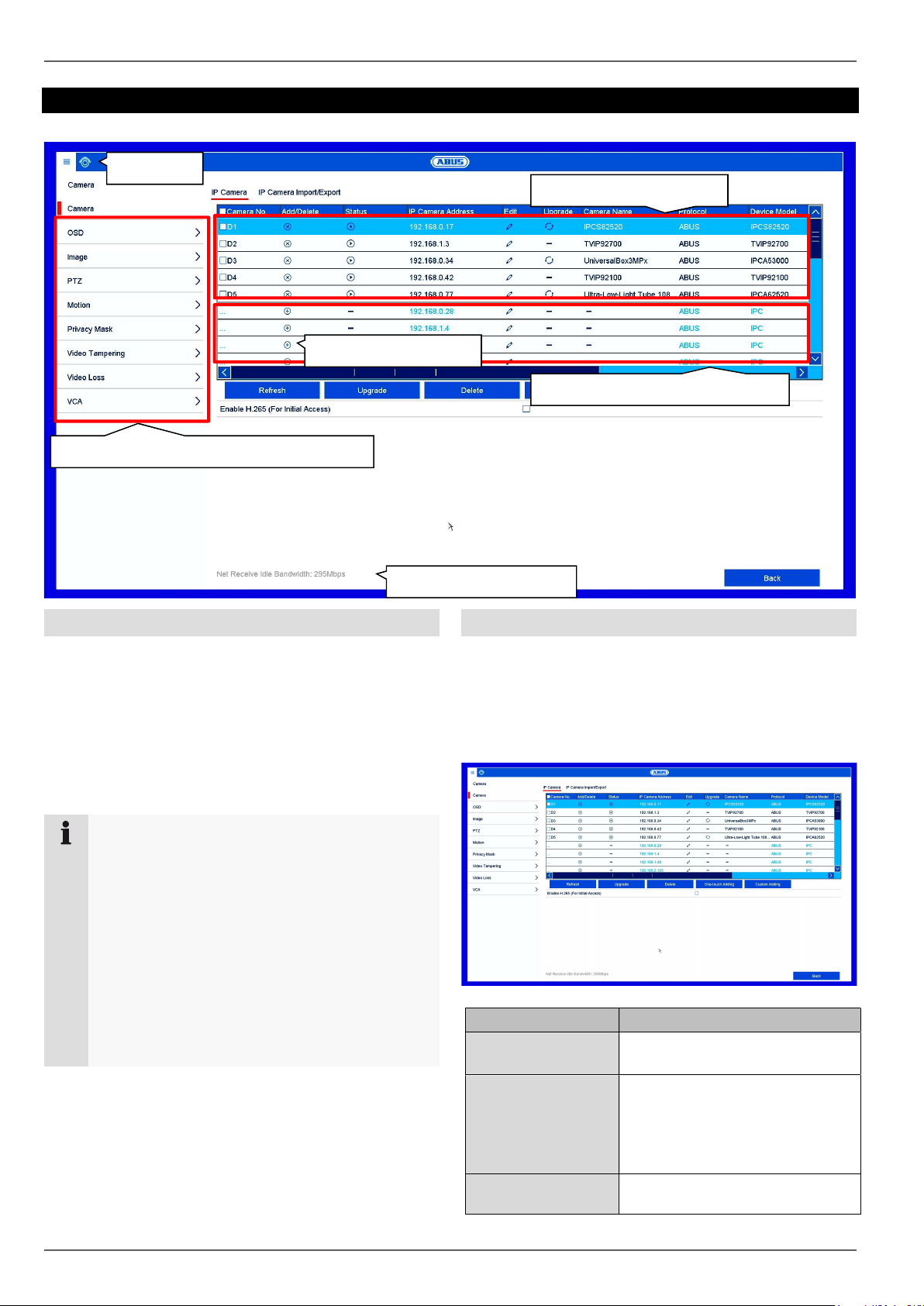
Setting: Camera
Setting: Camera
Live
Configured cameras
Add cameras
Available cameras in the network
Camera configuration (deep integration)
Available bandwidth
General information on managing cameras
The menu contains an overview of all cameras currently
found on the network and a status display of cameras
already integrated.
From here, new cameras can be added, the network
configuration can be adjusted and advanced settings
(deep integration) for the camera functions like motion
detection, image settings and VCA can be set.
Note
Please note the possible limitations of some
camera models in the “Compatibility” section at
the beginning of the guide.
If the desired parameter (e.g.: setting the motion
screen) is not adjustable via the recorder,
complete this adjustment using your camera’s
web interface.
Even if a camera function cannot be configured
via the recorder, the trigger signal of all
compatible cameras is always supported.
Camera
Add new cameras or edit the network configuration of
already programmed cameras here.
IP Camera tab
Parameter Setting
Camera No. Channel port starting with
D1…D32.
Add/Delete
Status
X: manually delete the camera
+: quickly add the camera. To do
this, the camera must be set to
the standard user and port
settings.
>: camera is online, click to view
a preview
44
Page 45

Setting: Camera
!: there is a camera fault or the
camera is offline.
IP Camera Address Displays the IP address.
Edit Manually change the settings for
the IP address, protocol, port
and user name.
Update Updates the network camera
firmware via USB.
Name Displays the camera name (see
OSD menu item).
Protocol Displays the manufacturer
device protocol.
Device Model Displays the camera model
number.
Management Port Saved management port
Firmware IP camera firmware version
Advanced
Settings
If available: Access to the
advanced settings
Click on Refresh to display the cameras on your
network.
Note
The update function via USB is not available for all
cameras. Alternatively, you can use the ABUS IP
Installer for the IP camera firmware update.
Click on Delete to delete the cameras you have already
added.
Click on Add All to add all the cameras displayed.
Select Custom Adding to manually add a camera.
Custom Adding
Here you can manually add network cameras by entering
the IP address and protocol and specifying the port and
user ID.
You can also use this menu to add network cameras
from other manufacturers, ONVIF-compatible cameras
and RTSP profiles.
Click on Search to refresh the device list.
Select a camera from the list and add to/change the
corresponding parameters when necessary:
Parameter Setting
Address IP address of the network camera.
Protocol Manufacturer communication protocol.
Check the compatibility list for this for
third-party manufacturers at
www.abus.com.
Port Communication port of the network
camera (usually port 80 or 8000)
User name User name for the admin account of the
network camera
Admin
password
Password for the admin account of the
network camera.
Note
If you are using a third-party manufacturer's
camera, please check in advance that it is on the
compatibility list at www.abus.com. The camera
functionality supported by the recorder may be
restricted if using certain models of cameras or
cameras from certain manufacturers.
Click on Add to transfer all manual settings for adding a
camera to the recorder.
Click on Protocol to create a custom RSTP profile for the
selected camera.
Note
If your camera model is not included in the
compatibility list, you also have the option of
setting up the camera on the recorder using an
RTSP streaming profile. To do this, you will need
the RTSP URL for the camera live stream, which
you can find in the user guide for your camera or
request from the manufacturer.
45
Protocol
Here you can create a custom RTSP profile, which can
then be assigned to a camera in the “Custom Adding”
menu.
Note
If you integrate a camera using RTSP, only the
video image from the camera will be available on
the recorder. Camera control functions (e.g. PTZ)
and motion detection are not supported.
Page 46

Setting: Camera
Parameter Setting
User
Protocol
Select a value between 1 and 16. The
settings will be saved here.
Protocol
Select any name.
Name
Stream Type All values below “Main Stream” will be
used for the main stream
(live+recording).
All values below “Substream” will be
used for the substream (multi view live).
Substream Enables the substream.
Type RTSP
Transfer
Protocol
Use the auto setting, provided that there
are no special requirements.
Port RTSP port entered
Path Specifies the RTSP streaming path on
the network camera.
Note
You can usually find information on the RTSP
streaming path in the camera manual or on the
manufacturer's website. Ask the manufacturer
directly when required if there is not enough
information on the path.
IP camera import/export tab
You can export or import all camera settings and
programmed camera lists to/from an external data
storage device here.
Click on Import to import a camera list from a data
storage device.
Click on Export to export a list of all saved cameras to an
external data storage device.
OSD
Typical layout of an RTSP streaming path:
rtsp://192.168.0.1:554/video.h264
Parameter Setting
Rtsp:// The protocol followed by “//”
192.168.0.1 IP address of the camera, separated by
dots
:554 Colon followed by the RTSP port for the
network camera
/video.h264 “/” followed by the path and streaming
parameter
Note
If your camera supports several streams, we
recommend using the high-quality stream for the
“Main Stream” setting and an alternative stream of
a lower quality for the “Substream” setting.
Set the On-Screen Display (OSD) of the camera here.
The “Name” parameter is an important setting that has
various implications:
Embedding of the text string in the camera’s live
image (OSD)
The camera’s archive name will be managed
using this identifier (playback)
Selection of the camera name in live image
(local/remote)
Selection of the camera in the system
configuration (local/remote)
Note
Even if the OSD function of the camera is not fully
supported, the “Name” setting is always available
and should be set so that it has an unambiguous
name for the camera selection in live image and
playback.
46
Page 47
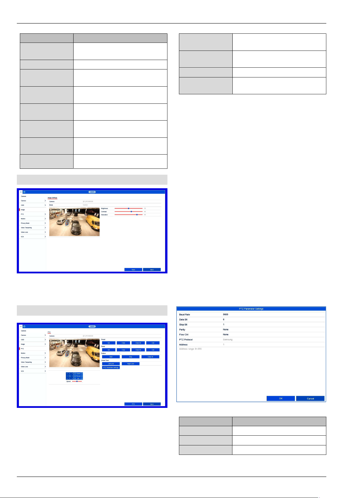
Setting: Camera
Parameter Setting
Camera
Selection of the camera channel
to be processed
Name
Display Name
Allocation of camera name
Activate/deactivate display of
camera name in the live view
Display Date
Activate/deactivate display of
date in the live view
Display Week
Display the calendar week for the
playback search
Date Format
Select the display format for the
date of the playback search
Time Format
Select the display format for the
time of the playback search
Display Mode
Settings for displaying the
camera name and date
Image
Select the camera channel to be processed under
“Camera” and adjust the image settings based on the
lighting conditions.
PTZ
Presets
Save and retrieve individual
preset positions.
Pattern
Save and retrieve a motion
pattern.
Patrol
Linear scan.
Save and retrieve patrols.
Horizontal panning of the camera
within the set limits.
Saving and retrieving presets
1. Use the arrow keys to navigate the camera to the
desired image section.
2. Save the preset position by assigning a code
(e.g. 1, 2...10) and then selecting the “Set”
button.
3. To retrieve the preset, enter your code and click
on “Retrieve”.
Saving and retrieving a pattern
1. Click on “Start” to start recording
2. Use the arrow keys to navigate the camera to the
desired image sections and positions.
3. Click on “Stop” to save the recording
Setting up and calling up patrols
1. Create several presets to use for the patrol
2. Click on “Set” to select a preset and set the dwell
time and speed
3. Add more presets to set up the required patrol
4. Click on “Retrieve” to start the patrol.
PTZ Settings
Select the camera channel to be processed under
“Camera”. To use these settings, the camera must have
a PTZ feature.
47
Parameter Setting
Baud Rate
Data Bit
Stop Bit
Define the transmission rate
Standard 8
Default 1
Page 48

Setting: Camera
Parity
Flow Ctrl
PTZ Protocol
Address
Note
These settings are only relevant for cameras with
external PTZ control.
Motion
No standard
No standard
Select the PTZ protocol
Select the camera ID
6. If you wish to record based on motion detection,
switch to the “Record” menu item and select the
relevant cameras under “Schedule”. Here you
can configure the schedule using the “Motion”
event in order to set up motion-detection-based
recording.
7. Click on Apply to save the settings.
Note
To record with the aid of motion detection, you
must set up the schedule under Record.
Note
For help in programming a Linkage Action via
the Settings button, see the “Linkage action”
section.
Private Zone
Motion detection is controlled solely using the motion
information on the recorder, which has been detected by
the camera.
If a live image from the camera is displayed in this
dialogue, you can configure the camera's motion screens
directly.
Note
The displayed settings for motion detection are
basic settings. In the camera's web interface,
detailed settings may be available.
If no live image from the camera is displayed in this
dialogue, all settings for motion screens and sensitivity
must be set directly in the camera's web interface. To set
up motion detection, proceed as follows:
1. Select the camera channel to be processed
under “Camera”.
2. Tick the “Enable Motion Detection” box and
define any other optional parameters under
“Settings”.
3. On a PC, open the web interface for the camera
you have selected and adjust the advanced
settings for the motion mask, threshold and
sensitivity.
4. Repeat the process for any additional cameras.
5. Click on Apply to save the settings.
Select the camera channel to be processed under
“Camera” and select the checkbox “Enable privacy
mask”.
Use the mouse pointer to drag the desired privacy masks
across the preview.
Note
You can set a maximum of four privacy masks.
To delete them, select either “Clear all” or the
desired mask on the right-hand side next to the
preview.
48
Page 49

Setting: Camera
Tamper Surveillance
The tamper surveillance function monitors the brightness
in the selected image area for darkening. If the lens is
covered, the tamper trigger will be set off.
Parameter Setting
Camera
Enable tamper
Select a camera.
Activate/deactivate the function.
surveillance
Sensitivity
Define the sensitivity level. The
further to the right the slider is
shifted, the more sensitive the
detection is.
Live image
Draw a screen in the displayed
live image using the mouse.
Delete
Settings
Deletes the current screen.
Set a linkage action.
Video Loss
The Video Loss function monitors the selected camera
channel for image loss.
Select the camera channel to be processed under
“Camera”.
Tick the Enable Video Loss Alarm box and define any
Linkage Actions under Settings as required.
VCA
The Video Content Analysis (VCA) function enables
event control through video analysis.
Then, if your camera model supports the functions, you
can configure one of the following VCA (video content
analysis) functions.
Note
Further information on the descriptions and uses
of the VCA functions can be found in the camera
user guide.
Some VCA functions may not be available,
depending on the camera model used. You can
find an overview in the “Compatibility” section.
VCA Role
Face detection Face detection
Tripwire detection Triggers recording when a
drawn line is crossed
Intrusion detection Triggers recording when an
object is present in a drawn
area for longer than a
certain amount of time
Defocus detection Triggers recording in the
event of defocus detection
Scene change detection Triggers recording in the
event of tampering through
scene changes
PIR Alarm Triggers recording when a
PIR sensor is detected
The VCA functions can be used in a similar way to
motion detection or alarm inputs as triggers for further
actions in the NVR (e.g.: recording, email, alarm outputs
etc...)
49
Page 50

Setting: Camera
Select the required VCA function to start configuration.
Different settings options are available for different VCA
functions. Here is a summary of the parameters:
Option Description
Arming Enables the VCA function in
the camera.
Settings Define settings for
responses in the event that
an alarm is triggered (email,
notification of Surveillance
Centre etc.)
Rule Select the number of rules.
Depending on the function,
several rules can be
configured simultaneously.
Rule Settings Select the sensitivity
settings for the function
(e.g.: object size, direction,
dwell time).
Draw Line Draw line for tripwire. The
line is created by positioning
two points on the live
image.
Draw Quadrilateral Draw area (quadrilateral) for
intrusion detection. The
area is created by
positioning four points.
Clear All Deletes all lines/areas of the
currently selected rule.
To fully enable the VCA function, confirm all settings by
clicking on “Apply”.
Note
Not all VCA functions have freely configurable
“rules” (lines, areas).
After all the VCA functions have been set, this
data is transferred to the IP camera. Analysis of
the VCA data takes place in the camera only. The
camera then transfers the VCA results only as
“meta-data” to the NVR.
50
Page 51

Setting: Recording
Setting: Recording
Set image quality
Schedul
General information on recording
In the Recordings menu, establish the basic settings for
the recording of the camera stream.
Along with the individual weekday settings, the camera’s
resolution settings, which are crucial in determining the
quality of the recorded image materials, can be set in the
“Parameter” submenu.
Schedule
Recording type
Copy schedule
Note
Both types of recording can be configured in
parallel for each camera.
Recording/instant image tab
There are two types of configuration and data recording
available:
Recording
Instant image
Configuration of video stream
recording from connected
network cameras. Continuous
data streams are saved on the
recorder.
Configuration of the single frame
recording from connected
network cameras. Only single
images are saved on the
recorder.
The schedule is used to specify the recording times and
triggers (recording type) for the cameras.
Note
As there is no difference between the settings for
the Record and Capture tabs, they are only listed
once.
51
Page 52

Setting: Recording
In the schedule, the hours for each day are listed from
left to right, and the days are listed from top to bottom.
On the right of the display, the colour key can be seen
meaning that in the time schedule set up, the recording
periods are displayed in the schedule in a different colour
depending on the ‘trigger’ (recording type) in question.
Coloured icon
Key
Continuous recording:
uninterrupted recording
Event: a recording is made
whenever any type of event
(motion, alarm input or VCA)
occurs.
Recording takes place only upon
motion detection.
Recording takes place only upon
alarm input (local/remote).
Recording takes place upon
motion detection or alarm input
(local/remote).
Recording takes place upon
None
simultaneous motion detection and
alarm input.
No recording takes place.
Select the camera and tick the Enable Schedule
box.
Click on a trigger and use your mouse to highlight
the time period within the schedule.
Alternatively, click on Edit to configure the type and
duration of the schedule down to the minute.
1. In the drop-down menu for “Schedule”, select the day
to be set.
2. Activate/deactivate “All Day”. If “All Day” is activated,
you cannot enter specific times as the setting now
applies to the whole day.
3. If you wish to enter specific time settings, deactivate
“All Day”.
4. Specify the recording type in the drop-down menu for
“Type”:
Duration
Event
Motion
Alarm
Motion or alarm
Motion and alarm
Event
5. If you are entering time-dependent settings, you can
define up to eight time slots, between 00:00 and 00:00
in each case, but the individual time slots must not
overlap.
Click on Copy to apply these settings to other days or
the entire week.
Finalise your settings on the record screen by clicking on
Apply and then OK.
Parameter
“Parameters” is where the quality settings for the
individual video streams are set up on the recorder.
There are three types of configuration available:
Recording
Quality settings for continuous and
event-based recording
Substream
Quality settings for the substream,
which is used mainly for the live
image display.
Instant image
Quality settings for capturing single
images
Note
If it is not possible to change the advanced
settings for resolution and bit-rate, this means that
the current recorder firmware does not support
this function.
52
Page 53

Setting: Recording
Record tab
The following setting options are available in this
submenu:
Parameter Setting
Camera
Encoding
Parameters
Stream Type
Resolution
Bit rate
Video Quality
Frame rate
Max. Bitrate
Mode
Max.
Bitrate(Kbps)
Max. Bitrate
Range
Recommended
Camera to be set
Stream to be set
Predefined video stream
Resolution of the camera
Select a variable or constant
bitrate
There are various quality levels:
+++: medium quality
++++++: high quality
Settings for the stream frame
rate
Select the mode for setting the
bitrate
Custom (32–3072)
Settings for the maximum bitrate
Recommended bit rate
depending on the set resolution,
frame rate etc.
Parameter Setting
Pre-play
Enables the pre-play storage for
individual stills. An attempt will
be made to save a time of up to
10 seconds.
Post-play
Enables the post-play storage for
individual stills.
Expired time
Specify how long data should be
held available for the respective
camera archive (overwriting will
be blocked).
Recording/instant
image
redundancy
Enables storage for the HDD
group “redundant” (not available
when the HDD group mode is
activated).
Record Audio
Enables the audio recording
(provided that the camera
delivers a signal).
Video stream
Select the stream source for the
recording.
Substream tab
The following parameters can be set:
Confirm the settings by clicking on Apply and exit the
menu by clicking on Back.
More settings:
The following detailed settings can be set individually for
each camera:
53
Parameter Setting
Camera
Stream Type
Resolution
Camera to be set
Predefined video stream
Auto, 4CIF(704x576),
CIF(352x288), QCIF(176x144)
Bitrate Type
Select a variable or constant
bitrate
Video Quality
There are various quality levels:
+++: medium quality
++++++: high quality
Frame rate
Settings for the stream frame
rate
Max. Bitrate
Mode
General,
custom (32–3072)
Page 54

Setting: Recording
Max.
Bitrate(Kbps)
Max. Bitrate
Range
Recommended
Confirm the settings by clicking on Apply and exit the
menu by clicking on Back.
Display of the maximum bitrate
192~320 (Kbps)
Instant image tab
The following parameters can be set:
Advanced settings
Overwrite Specify whether older recordings
should be overwritten when the
hard disk drive is full.
Parameter Setting
Camera
Parameter type
Resolution
Picture Quality
Interval
Confirm the settings by clicking on Apply and exit the
menu by clicking on Back.
Camera to be set
Individual settings for continuous
and event recording
Auto, 4CIF(704x576),
CIF(352x288), QCIF(176x144)
There are various quality levels:
+++: medium quality
++++++: high quality
Period after which single images
are saved (between 1 second
and
24 hours)
54
Page 55

Holiday
Setting: Recording
In this submenu, there are 32 different recording settings
for holidays or bank holidays.
The holiday schedule has a higher priority than the
normal recording schedule and, when enabled, overrides
it.
Name
Manually enter the name of the
holiday or bank holiday
Armed
Model
Start time
End time
Enable or disable the holiday set
By Date/By Week/By Month
Select the start date/start time
Select the end date/end time
Confirm your settings by clicking on Apply and then OK.
If the holiday mode setting is enabled, a “Holiday” entry
for the configuration of the recording schedule for the
holiday period will appear in the “Schedule” menu.
Click on the “Edit” icon to apply these settings.
55
Page 56

Setting: HDD
disk drives have to be initialised
Setting: HDD
Total storage
General information on HDD
Manage local and external memory drives in the HDD
section. Depending on the recorder model, 2–8 internal
hard disk drives can be managed. In addition, the
memory can be flexibly expanded by using network hard
disk drives.
Note
The installed hard
before the device can be used for recording. It is
only then that the device will recognise the hard
disk drive.
Warning
All data will be deleted from the hard disk drive
during initialisation.
Ensure data is backed up beforehand.
Add NAS
General
Set the configuration of the individual hard disk drives
and initialise new hard disk drives here.
HDD Information Description
Label Shows the internal connection
number
Capacity Hard disk drive capacity (in GB).
Status Shows the current status of the
hard disk drives:
Not initialised
Normal
Error
Standby
Attributes
Read-only: write protection
R/W: read and write
56
Page 57

When using NetHDDs, ensure that your network is
Setting: HDD
Type Local: Hard disk drive
NAS: Network hard disc drive
IP SAN: iSCSI volume
Free Space Shows the approximate amount of
free memory for recordings
Group Group ID
Edit HDD Settings
Delete Remove the hard disk drive
Initialising the hard disk drive
1. Select the hard disk drive by ticking the box.
2. Click on Init to start the process.
3. The status bar will show the progress of the
initialisation.
4. Once the process has finished, the hard disk drive
will appear.
Add NetHDD
Additional data storage devices can be added to enable
storage across the network.
Warning
Parameter
NetHDD
Type
Description
Choose from eight NetHDDs.
NAS: For this setting, your
network storage must support the
NFS file system.
IP SAN:For this setting, your
network storage must support the
iSCSI protocol.
IP address
Enter the network storage IP
address.
NetHDD Directory
Enter the storage path or iSCSI
target.
Note
Generally, a NFS path is indicated as follows:
“/volume1/ABUS-Recorder”.
Generally, an iSCSI path is indicated as follows:
“iqn.2010-10.Synology-iSCSI:VirtualDisk.01”
Always pay attention to upper and lowercase
letters when using a path description for network
storage.
of a sufficient size.
Note
The playback of recorded data may be slower if
you use NetHDDs than if you are using the
internal hard disk drives.
Click on Add to add a NetHDD.
Click on Search to identify the network storage and then
click on OK to add the NetHDD.
The NetHDD must be initialised before use.
Advanced settings
Here you can define the settings for the storage mode of
individual cameras and hard disk drives.
Disk mode tab
By clicking on the “Enable RAID” button, the integrated
RAID function will be enabled.
You will need to restart the recorder for this procedure.
Note
The “RAID” option is only available for select
recorder models. Please check the technical data
of the recorder.
57
Page 58

Setting: HDD
Storage mode tab
Set the recorder’s storage mode in this menu. Two
different storage modes are available in order to either
divide video data among all the hard disk drives or to
allow for targeted write operations for individual storage
devices.
Mode: Quota
Enable HDD
Sleeping
1. Use Copy to specify if the setting is to be applied to
all cameras.
2. Confirm the settings by clicking on Apply and exit the
menu by clicking on OK.
3. Click on Apply and confirm the reboot in the next
window by clicking on OK.
Mode: Group
When this function is activated,
idle hard disk drives go into
standby mode.
In this mode, video data is divided between the total
number of data storage devices connected and written
onto them.
Camera
Used Video
Capacity
Used Picture
Capacity
HDD Capacity
(GB)
Max. Record
Capacity (GB)
Selection of the camera channel
to be processed
Video storage space currently in
use on the linked data storage
devices.
Picture storage space currently
in use on the linked data storage
devices.
Total available hard disk drive
capacity (in GB).
Specify the maximum video
recording size on the linked data
storage devices for each camera.
In this mode, video data can be specifically (and also
redundantly) stored on selected data storage devices.
Here, the storage devices are organised into “groups”. A
group must include at least one HDD.
Parameter
Record on HDD
Group
Network Camera
Enable HDD
Sleeping
The HDD groups are configured in the General menu. To
do this, click on to open the HDD group settings.
Setting
Select HDD group
Select which cameras should be
stored in the group currently
selected.
When this function is activated,
idle hard disk drives go into
standby mode.
Max. Picture
Capacity (GB)
Specify the maximum picture
recording size on the linked data
storage devices for each camera.
58
Page 59
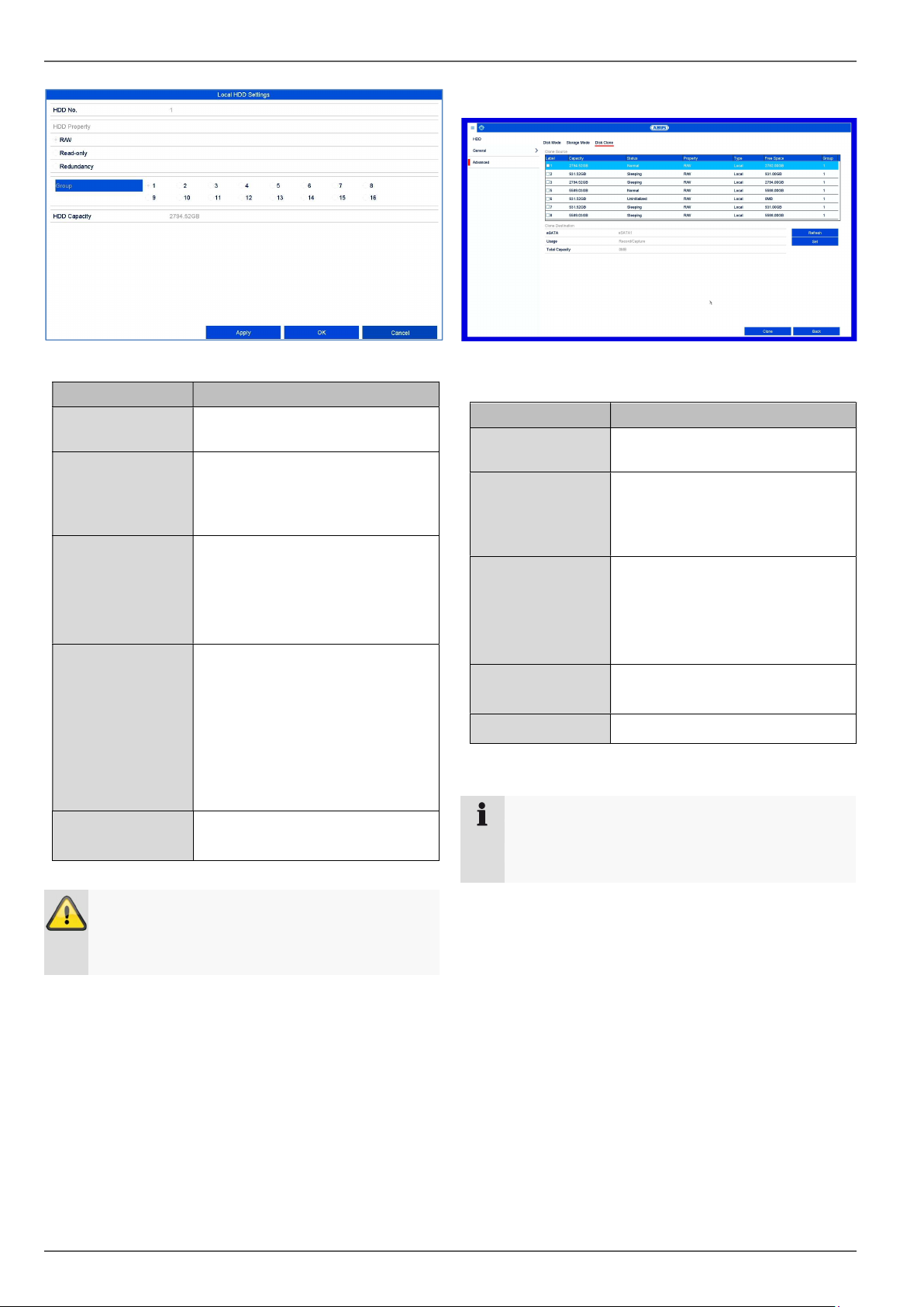
Setting: HDD
Clone drive tab
Parameter
HDD No.
R/W
Read-only
Redundancy
Group
Description
Internal hard disk drive number
for the recorder.
In this mode, video data is
written onto the data storage
device and can also be read
(default setting).
In this mode, no video data is
written onto the data storage
device. This setting is useful if
you want to stop data from being
overwritten after an event.
In this mode, video data will be
redundantly stored on all data
storage devices with the
"Redundancy" setting. For this
purpose, the “Redundancy”
button in the “Recording
Parameter More Settings”
menu must be pressed.
Allocate the data storage device
to an HDD group.
Hard disk drives can be cloned onto eSATA storage
devices via the submenu in the case of an impending
HDD failure or a critical incident.
Clone
eSATA
Use
Total capacity
Set
Cloning
Note
The “Cloning” option is only available on select
recorder models with an eSATA interface. Please
check the technical data of the recorder.
Setting
Here you can select the eSATA
interface
Current intended use of the
eSATA interface. The setting
must be on Export for the clone
procedure.
Capacity of the eSATA storage
device. In a clone procedure, the
eSATA storage device must at
least be as large as the storage
device that will be cloned.
Configure the intended use of
the eSATA interface.
Starting the cloning procedure
Important:
If only one hard disk drive is installed and this is
set to "Read-only", the device cannot be used for
recording.
59
Page 60

Setting: HDD
RAID is a software RAID function. This means that
RAID
In this menu you can create a RAID array for recording
video data on the recorder.
Important:
RAID data is managed via the recorder's
integrated CPU. If the function is enabled, the
INPUT bitrate of the NVR is reduced by around
40%.
Hot spare
Array tab
Free data storage devices which
are not assigned to a RAID array
can be defined as “hot spares”.
These data storage devices are
not used by the system initially. If
there is an error in a disk which
is part of a RAID array, the hot
spare data storage device is
immediately activated for use.
Note
If you would like to learn more about using RAID,
we advise you to consult specialist literature on
the subject.
Physical disk tab
This view shows a list of all the data storage devices
connected to the NVR. The following options are
available for further configuration:
Parameter
One-touch
configuration
Create
Setting
Automatically creates a RAID
array from all the free data
storage devices.
Create a RAID array manually.
The following RAID types can be
used: RAID0, RAID1, RAID5,
RAID10.
This view shows the current status of the RAID array.
The following actions can be performed:
Parameter
Rebuild
Delete
Setting
Carry out a manual rebuild of the
array. This rebuilds the data
structure of the RAID array.
Delete the RAID array. This
renders the data storage devices
“free” again, such that they can
be used for RAID configurations
again.
Firmware tab
Displays the firmware features of the RAID controller.
60
Page 61
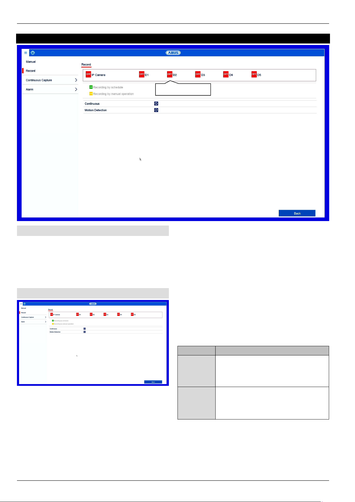
Panic recording
Panic recording
Snapshots
General information on panic recording
The Panic recording menu enables instant actions to be
triggered for recordings and switching outputs on the
recorder. All actions in the Panic recording menu have a
higher priority than the configured schedules in order to
be able to trigger a fast reaction.
Recording
Press the REC button in the live image or navigate to
“Continuous recording” or “Motion Recording” under
Panic Recording in the main menu to start manual
picture/video recording. The settings are identical for
snapshots and so they will only be described once.
Select the settings for all cameras. Click on “Off” or “On”
to change the settings.
“On (green)” “Off (red)”
Manually stop recording
“Off (red)” “On (yellow)”
Manual continuous recording
“On (yellow)” “Off (red)”
Manual continuous recording is stopped and if a
schedule has been configured for the camera, it will be
activated automatically (green).
Parameter Description
Continuous
recording
Motion
detection
Click on the icon to activate continuous
recording for all channels for the whole
day.
Click on “Yes” to confirm your selection.
Click on the icon to activate motion
detection for all channels for the whole
day.
Click on “Yes” to confirm your selection.
If a recording is started manually, it also has to be
stopped manually. All manual recordings will be
deactivated and the schedule activated when the
recorder is rebooted.
61
Page 62

Panic recording
Continuous Capture
Click on the camera channel to activate the function.
ON green = snapshots according to time schedule
ON yellow = snapshots captured by manual operation
Alarm
Here you can select the alarm output which should be
switched in the event of manual management.
You can switch several alarm outputs in the event of a
manual response.
Select Trigger to activate the selected alarm output.
Click on Trigger All to activate all of the alarm outputs.
Click on Clear All to remove the settings.
62
Page 63

VCA search
VCA event list
VCA search
Event playback
General information on VCA search
In the info menu, select the “VCA Search” item to analyse
video data recorded using VCA functions.
VCA events can also be analysed via the playback view
of individual cameras. The VCA Search menu, however,
allows you to search through the VCA events of all
connected cameras and to perform a data export directly.
Note
In the “Compatibility” section, check whether VCA
is supported by the selected camera.
Data export
Behaviour Search
In the menu item Behaviour Search, all “Tripwire” and
“Intrusion Detection” recordings can be analysed in a
targeted way. The following parameters can be set for
the search:
Parameter Description
IP Camera Select one or more recorded camera
channels.
Start time Select the start time.
End time Select the end time.
Type Select the recording type.
The search result is displayed in a new window.
Select from a table or a list view.
63
Page 64

VCA search
Behaviour Search: Table view
Face Search
Behaviour Search: List view
The following options are available in the results search:
Parameter Description
Playback Select a line by clicking on the Play icon
. The recording is shown in the preview
window. Using the playback controls
displayed below the image, the recording
can be played back.
Browse When several pages of results have
been found, navigate through the search
results using the icons
<< < > >>.
Select Select one or more recordings by clicking
on the checkboxes in the results list.
Export Export all selected data to an external
data storage device using the button
“Export”/”Export All”.
In the Face Search menu item, “Face Detection”
recordings can be analysed in a targeted way. The
following parameters can be set for the search:
Parameter Description
IP Camera Select one or more recorded camera
channels.
Start time Select the start time.
End time Select the end time.
The search result is displayed in a new window.
Select from a table or a list view.
Face Search: Table view
Face Search: List view
64
Page 65

VCA search
People Counting
In the “People Counting” menu item, people counting
statistics can be analysed by IP cameras using “Object
Counting”.
Note
Make sure that “Object Counting” recording inside
the IP camera has been set up beforehand.
Recording in the IP camera requires an SD card.
The following parameters can be set for the search:
Parameter Description
Camera Select a camera with the “Object
Counting” function enabled.
Report Type Select the report type here. The following
filters can be set: daily report, weekly
report, monthly report or annual report.
The arrangement of the X and Y axes on
the graph changes according to the
selection.
Statistics
Time
Counting Using the button, the counter data from
Export Export the counter data to an external
In the results graph, the counters for “People Entered”
and “People Exited” are displayed in accordance with
the pre-set parameters.
Select the point in time at which counting
should begin.
the camera is read and the results
displayed.
data storage device.
Parameter Description
People
Entered
Number of objects which have crossed
the counter line in the direction of the
entrance.
People
Exited
Number of objects which have crossed
the counter line in the direction of the
exit.
65
Page 66

Video Export
Video Export
General information on video export
To open the video export menu, select the “Export” item
in the info menu. From here, data can be exported to
external storage devices from all cameras at once.
Note
The export function is used to store important
recordings on connected external media, such as:
USB media
USB hard disk drives
DVD writers
Selection
Duration
Event
Image
Explanation
Export video data which was
recorded with continuous record.
Export video data which was
recorded with event record.
Export snapshots.
Duration/Event/Image
Start the export of the recorder’s video data from here.
Parameter Description
IP Camera Select one or more recorded camera
channels.
Recording
Type
Filters Select the event type.
Image Type Select the event type.
File Type Select whether all data or only
Start time Set the start time.
End time Set the end time.
Select the recording type.
locked/unlocked data should be
exported.
66
Page 67

Note
The “Duration”, “Event” and “Picture” sub-menus
are similar in structure and will therefore not be
described separately.
1. Enter the parameters.
2. Click on Search to start the search and the events
screen will appear.
Select the view using the available tabs “Table” or
“List”
The file size of each of the recordings and the total
size of all recordings found are displayed.
Video Export
4. Select the connected medium to be used for storage
from the drop-down menu.
5. If the medium is not displayed in the list, click on
Refresh.
If the medium is still not displayed in the list,
disconnect it from the device and then reconnect it.
See also the manufacturer's specifications.
6. Click on Export to start exporting. The progress of
the storage process will then be displayed.
Click on to view the corresponding recording.
Click on to lock and unlock a file. Locked files
can no longer be overwritten by the system.
3. Click on Export to go to the Export screen.
Note
Once the storage process is completed, you can
select the data on the medium and play it back on
the player (which has to be exported separately).
This way you can check that the export was
successful.
67
Page 68

Maintenance
Maintenance
General information on maintenance
Select the “Maintenance” item in the overview menu to
carry out system maintenance if problems arise.
Note
This menu is used for device maintenance and
should only be used by experienced users.
In this menu you can check important status information
such as network capacity, you can import and export
configuration data and also reset the recorder to the
default settings.
Menu Setting
System Info Device information (Serial No.,
Firmware Status etc.)
Log information In Log Information (=log file), you
can search for recordings or
information (S.M.A.R.T. hard disk
drive status) by certain criteria,
such as alarm, exception,
operation or information.
Import/Export Import and export settings
Update Performs a firmware upgrade
Default Resets the system
Net Detect Displays the transmission and
reception rate of the recorder
HDD Detect Checks the hard disk drive for
errors
68
Page 69

Maintenance
System Info
The information menu shows the technical data for the
device and information on the various settings of the
cameras, recording, alarm, network and HDD. This can
be useful for support queries, for example.
Log search
IP Conflicted
Network Disconnected
Exception Recording
Video input/output signals
not equal
Recording Buffer
Operation
All
Power On
Local: Unscheduled
Shutdown
Local: Shutdown, Reboot,
Login, Logout
Local: Change Settings
Local: Update
Local: Start Recording
Information
All
HDD Information
HDD S.M.A.R.T.
Start Recording
Stop Recording
Delete Expired Record
1. Select the event you wish to search for in the log and
then select a sub-parameter.
2. Enter the date and time under Start Time and End
Time, then click on Search.
3. The results will then be displayed in a pop-up
window:
Note
You can search for “events” according to the
following main types/events/parameters:
All
Alarm
Warning
Operation
Information
Filter1 Filter2
All Alarm
Exception
All
Motion detection
Start/stop
Start/stop video tampering
surveillance
All
Video Signal Loss
Illegal Login
HDD Full
HDD Error
You can change the page using the navigation bar:
(1) (2)(3) (4) (5) (6)
69
Page 70

Maintenance
enter it in field (5)
are carried out in the same way
Note
To scroll forwards or backwards press (3) or (2).
To jump to the first or last page press (4) or (1).
To go to a specific page number
and confirm by clicking on (6).
Click on the “Details” icon for more information.
Click on the “Play” icon to start the recording for the
event as required.
Click on Export to save the log file on a USB
medium.
Import/Export
Insert the USB stick into one of the device's
USB ports.
1. Select the USB port, clicking on Refresh, if
necessary.
2. Select the update file and click on Update.
3. Wait until the device reboots.
4. If necessary, check the firmware status under
Information in the Maintenance menu. Performing a
system reset
Note
Upgrades via FTP
as detailed above.
The PC must be on the same local network.
Set up a PC as an FTP server.
Enter the IP address of the FTP server .
Default
Note
The configuration data contains all of the settings
for the device that have been adjusted since it
was started up. This data can be saved on a USB
medium and then used to configure another
device in exactly the same way, for example.
Update
Note
A device can be upgraded from a USB medium or
via the network
via FTP.
Copy the upgrade file with the *.mav file
extension onto the main directory of a USB
stick.
Note
This process involves the device being reset to
the default factory settings.
Warning
All settings adjusted since the device was started
up will be deleted (cameras, recording settings,
PTZ, alarms etc.)
Avoid loss of data by saving the settings
beforehand. It can be re-imported once the
system has been reset.
70
Page 71

Maintenance
Net Detect
Information regarding the network traffic and network
interfaces is shown here.
Traffic tab
The network graphs can be used to measure continuous
traffic on the recorder. The amount of data sent and
received is shown in graph form.
Depending on the network settings, the status and
information for one or two network connections is shown
in the field underneath the graph.
Note
This view allows for the analysis of network and
performance problems with the recorder.
Network Detection tab
Under “Network Delay, Packet Loss Test”, you can check
the connection to another device, such as a computer
(‘pinging’). Enter the network address of the device to be
checked (e.g. 192.168.0.25) and click on Test.
Information on two parameters will appear:
Parameter Setting
Average
delay
Packet loss
rate:
The time the pinged device needs to
reply.
Displays the percentage of packets
that were not transmitted.
Sending
Receiving
Shows the amount of data (in
Mbit/s) currently being sent out
by the recorder. The value
increases as more users access
video streams from the recorder
over the network (web, app, PC
application and network storage).
Once the recorder limit value has
been reached or exceeded, it will
no longer be possible for all
requested streams to be
displayed.
Shows the amount of data (in
Mbit/s) currently being received
by the recorder. The value
increases as more IP cameras
are added and as the bitrate of
the camera stream is set to be
higher.
Once the recorder limit value has
been reached or exceeded, the
recorder will switch off camera
channels.
Note
If the packet loss rate is high, we recommend that
the “Network Delay, Packet Loss Test” is
repeated.
Note
If the packet loss rate is still high, you should
check that the network cables are correct and not
damaged.
The higher the packet loss rate, the poorer the
connection between the pinged device and the
recorder.
Under “Network Packet Export”, you can export the
settings of the individual connections or, depending on
the setting,
the connection.
1. For “Device Name”, select a storage medium to save
the settings to.
2. Click on Export.
71
Page 72
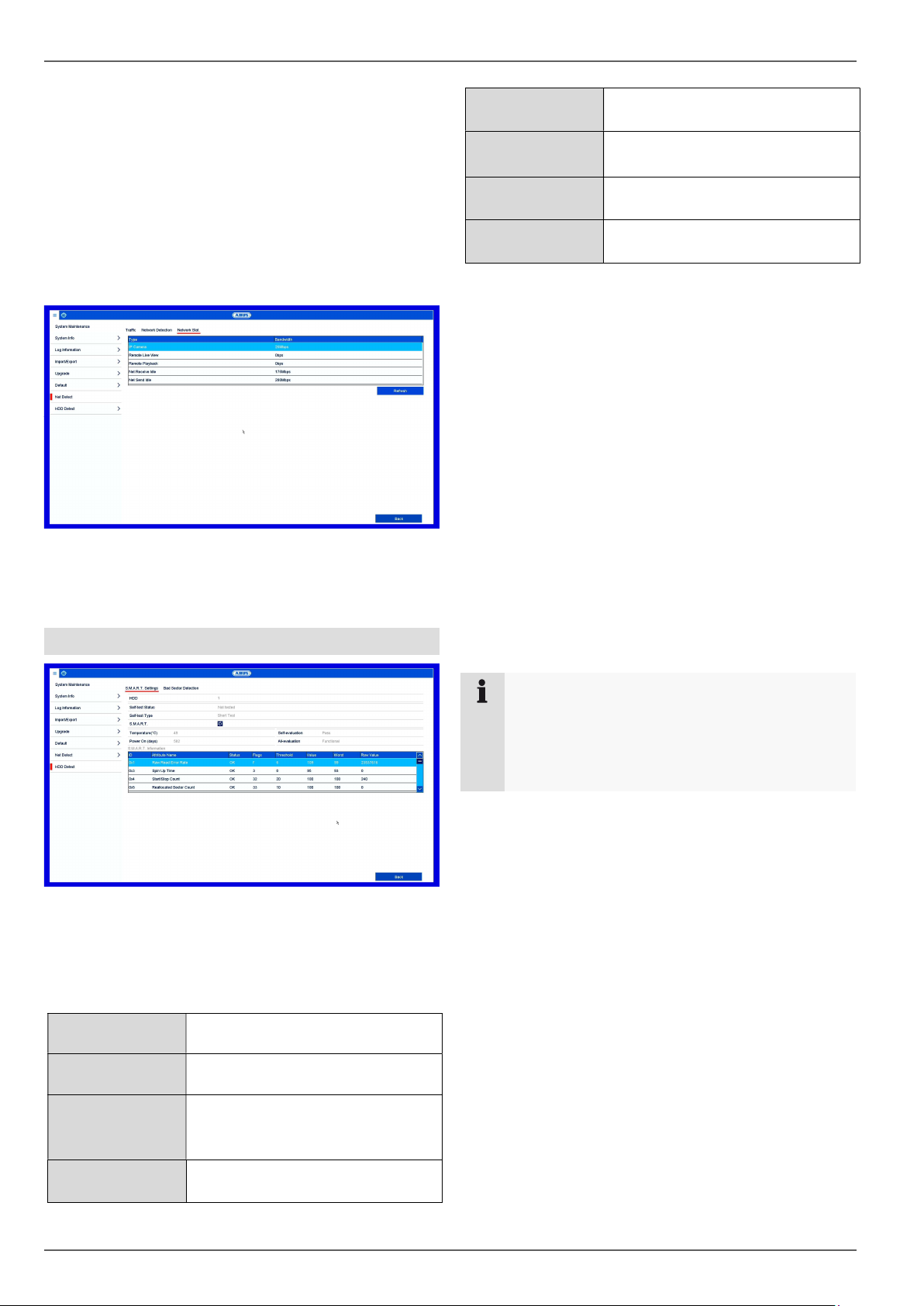
Maintenance
After the progress display finishes and initialisation is
successful, an information window will appear. Close
it by clicking on OK.
Click on Status to display the status of the LAN
connections (connected/not connected).
Click on Net Detect to change your network settings.
Network Stat. tab
The bandwidth used by the device is displayed under this
tab.
You can refresh the data by clicking on Refresh.
HDD Detect
Temperature (°C) Shows the hard disk drive
temperature
Power On
(days)
Shows the operating days of the
hard disk drive
Self-evaluation Shows the status of the self-
evaluation
Complete
Shows the status of the evaluation
evaluation
Confirm the settings by clicking on Apply and exit the
menu by clicking on OK.
Checking the hard disk drive status
You can check the status of each hard disk drive in the
“System Maintenance” menu. The S.M.A.R.T (SelfMonitoring, Analysis and Reporting Technology)
information is stored in the log data.
Open the log file and search by
information/S.M.A.R.T. Hard disk drive. Setting up the
hard disk drive alarms
You can specify which alarms will inform you of hard
disk drive errors.
To do this, open “Exception” in the “Settings” menu.
Click on the “S.M.A.R.T” submenu.
This submenu gives you the option to check the hard disk
drive for errors.
HDD Selection of the hard disk drive to
be processed
Self-test Status Shows the status of the current self-
test
Self-test Type Select the type of self-test
Short Test/Expanded
Test/Conveyance Test
S.M.A.R.T Click on the icon to start the self-
test
Note
Select Lock to lock the operating menu.
Select Shutdown to switch the device off.
Select Reboot to reboot the system (switch off
and back on).
72
Page 73

Fault rectification
Video cable is not connected properly
Audio cable is not connected properly
Check the power supply and power switch of
Audio connecting cable is damaged
WEEE (Waste Electrical
for waste equipment can be
Fault rectification
Before contacting the Service department, read the following information to determine the possible cause of any fault.
Fault Cause Solution
No power Power cable not connected Connect the power cable properly to the
socket
Power switch at OFF Set power switch to ON
No power supplied from socket If necessary, use another device at the
socket
No picture The screen is not set to receive Set correct video input mode, until an image
is received from the recorder
Connect the video cable properly
The connected monitor is switched off Switch on monitor
No sound
Devices connected via audio cable are not
switched on
Hard disk drive not functioning Connection cable is not connected properly Connect the cable properly
Hard disk drive faulty or incompatible with the
system
USB connection not functioning Device is not supported Connect correct USB medium, USB 2.0
USB Hub was used Connect USB medium directly
Network access not possible Network cable connection loose Insert network cable.
Network settings (DCHP, IP address etc.)
incorrect
Recording is not possible No HDD, or HDD not initialised Install and initialise hard disk drive
Sudden switch-off The internal temperature of the device is too
high
Connect the audio cable properly
the connected audio device
Replace cable
Replace the hard disk drive with a
recommended hard disk drive
Check and if necessary correct network
configuration, see page 27.
Clean the device and/or remove any objects
impeding the ventilation
Disposal
Notes on EC directives for waste electrical
and electronic equipment
For the protection of the environment, at the end of its
useful lifespan, the device may not be disposed of in
household waste. Disposal can be carried out at suitable
national collection points. Obey local regulations when
disposing of material.
Dispose of the device in accordance with EU
Directive 2011/65/EU and Electronic Equipment). If you have any
questions, please contact the municipal
authority responsible for disposal. Information
on collection points
obtained from the local or district authorities,
local waste disposal companies or the dealer.
Notes on RoHS EU Directive
The device complies with the RoHS directive.
Compliance with the RoHS directive means that the
product or component contains none of the following
substances in higher concentrations than the highest
concentrations in homogeneous materials, unless the
substance is part of an application that is excluded from
the RoHS Directive:
a) 0.1 % lead (by weight)
b) Mercury
c) Hexavalent chromium
d) Polybrominated biphenyl (PBB) and polybrominated
diphenyl ether
e) 0.01 % cadmium (by weight).
73
Page 74

ABUS
Embedded NVR Recorder
Local user interface user guide
Manufacturer
ABUS Security-Center GmbH & Co. KG
Linker Kreuthweg 5
86444 Affing (Germany)
Page 75
ABUS embedded NVR
Web interface user manual
Date: 16.01.2017
Firmware: 3.4.6
Page 76

This user manual contains important information on
starting operation and using the device.
Make sure that this user manual is handed over when the
product is given to other persons.
Keep this user manual to consult later.
You will find a list of contents with the corresponding
page numbers in the contents.
Page 77

Contents
3
Important safety information .......................................................................................................................................... 5
Explanation of symbols .................................................................................................................................................... 5
Intended use .................................................................................................................................................................... 5
General ............................................................................................................................................................................ 5
Power supply ................................................................................................................................................................... 5
Installation ........................................................................................................................................................................ 6
Children ............................................................................................................................................................................ 6
EU Directives ................................................................................................................................................................... 6
Compatibility .................................................................................................................................................................... 7
General ............................................................................................................................................................................ 7
Compatible recorders ....................................................................................................................................................... 7
Compatible browsers ....................................................................................................................................................... 7
Image display performance.............................................................................................................................................. 8
System requirements ....................................................................................................................................................... 8
Performance table ............................................................................................................................................................ 9
Introduction .................................................................................................................................................................... 10
General information ....................................................................................................................................................... 10
Internal access (LAN) .................................................................................................................................................... 10
Local interface ............................................................................................................................................................... 10
ABUS IP installer ........................................................................................................................................................... 10
Windows UPnP search .................................................................................................................................................. 10
External access (internet) .............................................................................................................................................. 11
Using IPv6 ..................................................................................................................................................................... 11
Dual-Stack and Dual-Stack Lite (DS Lite) ..................................................................................................................... 11
Setting up port forwarding (IPv4)................................................................................................................................... 11
Setting up the ABUS server (IPv4) ................................................................................................................................ 12
DDNS for IPv6 (IPv6) .................................................................................................................................................... 12
Access to DS Lite connections (IPv6) ........................................................................................................................... 12
Logging in for the first time............................................................................................................................................. 13
Live cast .......................................................................................................................................................................... 14
General information on live image ................................................................................................................................. 14
Live image function areas .............................................................................................................................................. 14
Using the menu bar ........................................................................................................................................................ 14
Using the camera list ..................................................................................................................................................... 14
Using the action bar ....................................................................................................................................................... 15
Using the view bar ......................................................................................................................................................... 15
PTZ control menu .......................................................................................................................................................... 16
Playback view ................................................................................................................................................................. 17
General information on playback ................................................................................................................................... 17
Playback function areas ................................................................................................................................................. 17
Using the archive list ...................................................................................................................................................... 18
Using the view bar ......................................................................................................................................................... 18
Using the playback controls ........................................................................................................................................... 18
Using the action bar ....................................................................................................................................................... 18
Export functions ............................................................................................................................................................. 19
Download ....................................................................................................................................................................... 19
Using the timeline and calendar .................................................................................................................................... 19
Image export ................................................................................................................................................................... 20
Image export .................................................................................................................................................................. 20
Settings ........................................................................................................................................................................... 21
General settings ............................................................................................................................................................. 21
Page 78

Contents
4
Setting: Local ................................................................................................................................................................. 22
General information on local settings ............................................................................................................................ 22
Live cast parameters ..................................................................................................................................................... 22
Record file settings ........................................................................................................................................................ 22
Image/clip settings ......................................................................................................................................................... 23
Setting: System .............................................................................................................................................................. 24
General information on system ...................................................................................................................................... 24
System settings .............................................................................................................................................................. 24
Overview ........................................................................................................................................................................ 24
Time settings ................................................................................................................................................................. 24
Output menu .................................................................................................................................................................. 25
Maintenance .................................................................................................................................................................. 25
Upgrade and maintenance ............................................................................................................................................ 25
Protocol ......................................................................................................................................................................... 25
Camera management .................................................................................................................................................... 25
Add manually ................................................................................................................................................................. 25
Quick add ...................................................................................................................................................................... 26
Custom protocol ............................................................................................................................................................ 26
Managing users ............................................................................................................................................................. 27
Fault rectification ........................................................................................................................................................... 28
Disposal .......................................................................................................................................................................... 28
Notes on EC directives for waste electrical and electronic equipment .......................................................................... 28
Notes on RoHS EU Directive ......................................................................................................................................... 28
Page 79

Important safety information
5
Important safety information
Explanation of symbols
The following symbols are used in this manual and on the
device:
Symbol
Signal
word
Meaning
Warning
Indicates a risk of injury or health
hazards.
Warning
Indicates a risk of injury or health
hazards caused by electrical
voltage.
Important
Indicates possible damage to the
device/accessories.
Note
Indicates important information.
The following annotations are used in the text:
Meaning
1. …
2. …
Required action to be carried out in a set order
…
…
List without a set order, given either in the text
or warning notice
Intended use
Only use the recorder for the purpose for which it was
built and designed. Any other use is considered
unintended!
This device may only be used for the following
purpose(s):
This recorder is used in combination with video signal
sources (network cameras) and video output devices
(TFT monitors) for property surveillance.
Note
Data storage is subject to national data privacy
guidelines.
When carrying out the installation advise your
customers of the existence of these guidelines.
General
Before using this recorder for the first time, please read
the following instructions carefully and observe all
warning information, even if you are familiar with the use
of such recorders.
Warning
All guarantee claims are invalid in the event of
damage caused by non-compliance with this user
manual.
We cannot be held liable for resulting damage.
Warning
In the event of personal or material damage
caused by improper operation or non-compliance
with the safety information, we cannot be held
liable.
All guarantee claims are void in such cases.
Retain this manual for future reference.
If you sell or pass on the recorder to third parties, you
must include these instructions with the device.
Power supply
Warning
Prevent data loss:
The recorder should only ever be used with a
device that is constantly connected to an
uninterruptible power supply (UPS) with surge
protection.
Warning
Modifications to the device invalidate the
guarantee.
Page 80

Important safety information
6
Installation
Observe all safety and operating instructions before
installing the device for the first time.
Only open the housing to install the hard disk drive.
Only install the software on devices that are
expressly suitable for the intended purpose.
Otherwise, damage to the device can occur.
Note
Compatible devices:
- NVR10010
- NVR10020
- NVR10030
- NVR10040
Warning
If in doubt, have the device installed by a
specialist technician rather than carrying it out
yourself.
Children
Keep electrical devices out of reach of children.
Never allow children to use electrical devices
unsupervised. Children may not always properly
identify possible hazards. Small parts may be fatal if
swallowed.
Keep packaging film away from children. There is a
risk of suffocation.
This device is not intended for children. If used
incorrectly, parts under spring tension may fly out and
cause injury to children (e.g. to eyes).
EU Directives
This device complies with the requirements of the EU
Low Voltage Directive (2014/35/EU), the EMC
Directive (2014/30/EU) and the RoHS Directive
(2011/65/EU). The declaration of conformity can be
obtained from:
ABUS Security-Center GmbH & Co. KG
Linker Kreuthweg 5
86444 Affing
GERMANY
To ensure this condition is maintained and that safe
operation is guaranteed, it is your obligation to observe
this user manual.
Please read the entire user manual carefully before
putting the product into operation, and pay attention to all
operating instructions and safety information.
All company names and product descriptions are
trademarks of the corresponding owner. All rights
reserved.
If you have any questions, please contact your specialist
installation contractor or specialist dealer.
Disclaimer
This user manual has been produced with the
greatest of care. Should you identify any
omissions or inaccuracies, please contact us at
the address shown on the back of the manual.
ABUS Security-Center GmbH does not accept any
liability for technical and typographical errors, and
reserves the right to make changes to the product
and user manuals at any time and without prior
warning. ABUS Security-Center GmbH is not
liable or responsible for direct or indirect damage
resulting from the equipment, performance and
use of this product. No guarantee is made for the
contents of this document.
Keep electrical devices out of reach of children. Never
allow children to use electrical devices unsupervised.
Page 81

Compatibility
7
Compatibility
General
This manual describes the use of the ABUS embedded
recorder via the integrated web server. Information on
compatible cameras and other components can be
found either in the basic manual (local interface) or on
the ABUS website.
When you first try to access the server on your
browser (on Windows), you will be prompted to install
a plug-in in order to use the web server. You will need
administrator rights on your PC to do this. Access to
the live images and recordings is only possible with the
plug-in installed.
Compatible recorders
Device type
Item number
NVR
NVR10010, NVR10020,
NVR10030, NVR10040
Compatible browsers
OS
Browser
Version
Windows
Internet Explorer
11 or higher
Windows
Firefox
49 or higher
MacOS
Safari
10 or higher
Due to strict guidelines, the following browsers do not
support the plug-in and are therefore not compatible:
Chrome (Google)
Edge (Microsoft)
Note
If you access the recorder web server using Safari
on MacOS, you will need to obtain the required
plug-in from the ABUS homepage
(http://www.abus.com). Search for the recorder
item number on the homepage and download the
plug-in from the item card in the "Downloads"
area.
Page 82

Compatibility
8
Image display performance
To display network camera video streams (both live
images and playback of recordings)
on your PC via the browser, the digitally compressed
data must be transmitted from the recorder to your PC
and then "decrypted". This process will take up a
different amount of processing power on your PC
depending on the camera resolution. The higher the
resolution and bit rate of the individual camera stream,
the greater the required processing power for the
decryption process.
If the number of camera streams to be displayed
exceeds the decoding power of the PC, the CPU
usage will reach 100% and operation will be slow.
Should this occur, reduce the number of cameras to be
displayed at the same time in live cast or playback
view.
The recorder web interface provides the option of
displaying a sub-stream (generally 720p or smaller) for
individual cameras in the live image to facilitate this.
This approach reduces the bandwidth and requires
less processing power for decryption on the PC.
In playback view, the cameras are played back in the
corresponding quality of the recording (main stream).
Depending on the application and camera type, this
may mean that not all cameras can be displayed at
once. Split the cameras into different views to work
around this limitation.
System requirements
Use up-to-date PC hardware (no older than two years)
in order to ensure the smooth operation of the software
in combination with cameras and the recorder. The
requirements for your PC system increase with the
number of camera channels, as well as with the related
video resolution and bit rate of the cameras. The
camera display (resolution, bit rate and number of
channels) strongly depends on the software functions
used (live image display, playback, time of analysis).
The following table provides a starting point and
reference for the PC configuration actually required:
Minimum requirement:
Operating
system
(32-bit/64-bit)
Windows 7, Windows 8, Windows 8.1,
Windows 10
CPU
Intel Pentium 4 3 Ghz or higher
RAM
1 GB or higher
VGA
256 MB or higher
Note
Use a 64-bit operating system with 4 GB or
higher, if possible, in order to achieve optimal
performance. The following table provides the
performance data for using and selecting a
suitable CPU.
Warning
Check your PC's CPU usage when displaying live
streams or playing back recorded data using the
Task Manager (on Windows).
CPU usage < 100%
Select sub-stream
Page 83

Compatibility
9
Performance table
CPU
i74470k
3.5 Ghz
E31230
3.3 Ghz
I54590
3.0 Ghz
FX8350
4.0 Ghz
I32100
3.1 Ghz
OS
Win7
Win7
Win7
Win7
Win8
CIF@512Kbit
64
64
64
64
47
VGA@1.25MBit
51
44
30
27
18
4CIF@1.5Mbit
59
55
37
33
23
WD1@2Mbit
41
33
24
20
16
720p@2Mbit
28
24
17
15
11
1080p@2Mbit
13
10 8 7
5
QXGA@4Mbit
11 8 7 6 4
The figures indicate the maximum amount of live
camera images which can be displayed simultaneously
in the web browser. The live images are transmitted
via the network as video streams. For this reason,
ensure that your network is sufficiently equipped to
handle this.
Note
The values given here were calculated under
optimal conditions (no background processes,
virus scans, etc.) Performance on your PC system
may vary depending on additional software
installed and background applications.
Page 84

Introduction
10
Introduction
General information
This manual describes the use of the ABUS embedded
recorder via the web interface using a web browser on a
remote PC on the network.
For this purpose the recorder must already by integrated
in your network in order to facilitate access via a PC. In
simple cases, both the PC and the recorder are located
on the same local network.
Note
Ensure that the recorder is connected directly to
your CCTV network (switch) via a network cable.
For optimal performance do not use a Wi-Fi
connection between the recorder and the CCTV
network.
Internal access (LAN)
The recorder is accessed by typing the IP address in the
navigation bar of the browser.
The following describes several different options for how
to determine the current IP address of your recorder in
order to access it via the local network.
Local interface
Open the overview menu on the recorder's local interface
and note the IP address.
ABUS IP installer
Install the ABUS IP installer (Windows) on your PC and
start the program. The program searches your local
network for ABUS network products.
Use the full-text search to filter result lists with lots of
entries by specific item numbers. Then double-click on
the list entry for your product to directly open the recorder
web interface.
Windows UPnP search
Open the network search using the "network" icon in the
Windows File Explorer. All devices on your network that
were detected via UPnP are displayed here. Since the
recorder supports this network service, you can open the
web interface directly by double-clicking on the icon with
the item number in the label field (e.g. NVR10040).
192.168.0.5
192.168.0.4
IP address
Double-click on search result
Full-text search
Network
Double-click on
recorder icon
Page 85

Introduction
11
External access (internet)
The recorder can also be accessed externally by typing
the IP address in the browser’s navigation bar. Since the
recorder is generally not accessible directly from the
internet, you must set up port forwarding on your router.
Accordingly, the router IP address must be entered as
the IP address in the navigation bar when accessing the
recorder via the internet (IPv4). Additional settings are
required for IPv6, which are described in detail below.
The network services on the recorder do not have to be
adapted for access to the web interface on the local
network. For external access, you may have to adjust
the default settings of the ports in order to enable
access.
The following points are important for remote access:
Notes on using IPv6
Setting up port forwarding on your router
Required ports for remote access to the web
interface: HTTP(S) and RTSP
Free DDNS service from ABUS: ABUS server
Access to DS Lite connections
Using IPv6
Modern internet providers switch what is known as "DualStack" internet access to the customer's landline
connection. This means that the router provides access
to the internet via both the IPv4 protocol and IPv6. The
ABUS embedded recorder supports both protocols as
standard. Since IP communication for remote
connections takes place between two end points, both
subscribers (recorder and receiving point) must use the
same communication protocol in order to successfully
establish a connection. The IPv6 protocol is not currently
widely available, so pure IPv6 communication is not
practical for the moment, especially if the receiving point
(e.g. the web browser on a laptop) is mobile and may
switch between IPv4 and IPv6 networks.
Note
As of 2016/2017: IPv6 is currently undergoing
global "roll-out". This means that increasingly
more providers are allowing for IPv6 access to the
internet. Check your internet connection, both on
the recorder and on the intended receiving points,
to take potential limitations and instructions for the
operation of the recorder into account ahead of
time.
We provide the following tips and instructions for setting
up external access to the ABUS embedded recorder,
which take both protocols into account.
Dual-Stack and Dual-Stack Lite (DS Lite)
As part of the global roll-out of IPv6, the IANA stipulated
that internet providers which use IPv6 must also allow
their customers to access the internet via IPv4, in order
to be able to access internet servers/services that are
only available on the IPv4 network. Since the global IPv4
address pool has already been used up, internet
providers that do not have enough ipV4 addresses use
an alternative technology known as "Dual-Stack Lite".
Note
Internet connections with "Dual-Stack Lite" have
significant limitations when using IPv4. If possible,
use a provider that employs actual Dual-Stack
technology or ask your provider whether your
Dual-Stack Lite access can be changed to a real
Dual-Stack connection.
Based on the fact that IPv6 is not available everywhere,
we recommend establishing your remote connection via
IPv4 (even with Dual-Stack connections). This
particularly applies to mobile networks, which are still in
the process of completely switching to IPv6 on end
devices, with a few exceptions (as of 2016/2017).
Setting up port forwarding (IPv4)
In order for the recorder (web interface) to be accessible
via the internet, the network service ports of the recorder
must be able to be accessed externally using port
forwarding on the router. Set up 1:1 port forwarding on
the router, which opens the HTTP(S) port of the recorder
as well as the RTSP port on the WAN connection of the
router.
Setup differs depending on your router's model. Refer to
the router manufacturer's instructions to find out how to
set up port forwarding on your router.
The rule should be structured according to the
following scheme (example):
External HTTP port (on the router): 80
External HTTPS port (on the router): 443
External RTSP port (on the router): 554
Forward to target address:
192.168.0.5 (local IP address of your recorder)
Page 86

Introduction
12
Internal HTTP port (on the recorder): 80
Internal HTTPS port (on the recorder): 443
Internal RTSP port (on the recorder): 554
Your router's IP address, which is displayed on the WAN
interface, is used as the external IP address.
To open the recorder's web interface via remote
connection, enter the following URL in the navigation bar
of the browser:
http://external-router-IP:80
https://external-router-IP:443
The externally forwarded RTSP port is automatically
used by the web interface and does not have to be
specified again.
Note
We recommend changing the default ports for port
forwarding in order to avoid an overlap with other
services (for example, port 443 is likely to be the
same port used by the web interface of the router
for external access). This also makes it easier to
set up forwarding for other devices later.
Setting up the ABUS server (IPv4)
Internet providers generally disconnect the internet
connection of the router for a few seconds every day.
During this process, the router is assigned a new IP
address. This means that for remote access to the web
interface of the recorder, the new valid IP address of the
router (WAN interface) has to be used.
In order to avoid having to check this address on a daily
basis, ABUS offers a free DDNS service: the ABUS
server. With this service, the router's external IP address
is assigned a host name on the server, which is matched
with the current IP and port information on a regular
basis.
Access to the recorder web interface then takes place
via the ABUS server host name:
http://meinrekorder.u21783.abus-server.com:1500
Go to https://www.abus-server.com to register for free
and set up your recorder.
The ABUS server only supports IPv4 addresses.
Instructions on how to set up your recorder for the ABUS
server are stored in the downloads area for the recorder
on http://www.abus.com.
DDNS for IPv6 (IPv6)
The supported DDNS providers for the ABUS embedded
recorder currently only allow for IPv4 DDNS
synchronisation. Another service is currently required to
run DDNS synchronisation for IPv6. Because, unlike with
IPv4, every device (recorder) with IPv6 receives a unique
global IP address, the current IPv6 address of the
recorder must be transmitted to the DDNS provider when
using DDNS for IPv6.
You can do this via your router, for example, if your
router supports this type of service.
AVM/Fritzbox/MyFritz recommendation:
The "MyFritz" service can detect all global IPv6
addresses of connected devices and provide them via
the MyFritz service as a DDNS host name.
Note
Network service ports (HTTP(S) and RTSP) must
be opened to use the web interface on the
recorder with IPv6 as well.
Access to DS Lite connections (IPv6)
Many internet providers use DS Lite to switch their
customers' connections to IPv6 access. With DS Lite
your router does not have full IPv4 access to the internet.
The IPv4 address that is assigned to the router is
segmented by what is known as a "CGN" (Carrier Grate
NAT). This means that an additional NAT is directly
connected by the provider for IPv4. As a result, NAT
configuration (port forwarding) for IPv4 is no longer
possible on the local router and therefore incoming IPv4
queries are discarded directly at the provider end (CGN).
It is then no longer possible to access your local devices
externally via IPv4.
Its is highly likely, however, that remote access to your
recorder's web interface will take place on an IPv4
network (receiving point). Additional services must be
used to allow external access in such cases.
Page 87

Introduction
13
Static-Access.NET/Portmapper/FIP-Box
recommendation:
The "Static-Access.NET" service makes it possible to
convert IPv4 data packets from an IPv4 network
(receiving point) into IPv6 packets. These IPv6 packets
can then be provided to the recorder via normal port
transfers on the router. Further details on this can be
found at http://www.static-access.net/.
Logging in for the first time
Once access to the recorder web interface has been
established, you will see the login screen on the
browser. Log in for the first time by entering your user
name and password and indicating your desired system
language.
If a notification for the plug-in download appears, this
means that the recorder plug-in is not yet installed on
your PC and must first be downloaded and installed
before you can proceed.
Note
You must have local administrator rights on your
PC to install the plug-in. Ensure that you have
these before starting the installation.
Open file "ABUS Rekorder Web-Plugin.exe" to start the
installation. Once the plug-in is installed, the web
interface and all of its functions can be used.
Note
The plug-in contains the video decryption software
for displaying live streams on your web browser.
Subsequent firmware updates may mean that the
plug-in also needs to be updated on your PC in
future. The web interface may then prompt you to
re-install the plug-in.
Plug-in download
Plug-in installation
Page 88

Live cast
14
Live cast
General information on live image
Live cast starts automatically once you have logged into
the web interface. The live image function provides the
option of displaying live images and executing camera
commands for all cameras connected to the recorder.
This is the core function of the recorder, in addition to
playback.
Double-clicking an image displays the selected camera
image in full screen or switches back to the original view.
Live image function areas
The live cast view is divided into the following function
areas:
Using the menu bar
The following options are available:
Using the camera list
The camera list contains all cameras connected to the
recorder. Double-clicking a camera name displays the
corresponding camera in the live image.
Parameter
Description
Menu bar
Global display of the configuration
and control menus
Camera list
Select from the connected
cameras for live cast
Action bar
Control camera commands and
carry out actions for the selected
camera (red frame)
View bar
Configure multi-view and
streaming options
PTZ control
Control menu for PT(Z) cameras
Parameter
Description
Activates the live image view (live
cast)
Changes to playback view
Changes to snapshot view
Changes to system settings
Action bar
Menu bar
PTZ control
View bar
Camera list
Logout
Page 89

Live cast
15
To display the camera at a specific position in the live
image (multi-view), proceed as follows:
1. Select the position in the live cast (red frame).
2. Double-click the desired camera in the camera
list.
3. The camera is displayed at the desired position.
The following functions/status displays are available in
the camera list:
The default setting for manual stream selection is "1".
This means that the high-resolution "main stream" of the
camera is displayed. This is the best option in most
cases. It is only practical to adjust the manual stream
selection if there is a risk of a performance bottleneck
during transmission:
If you wish to display lots of cameras at the same
time (nine or more), the processing power of your
PC may not be sufficient to decode all video
streams. Change the setting to sub-stream "2".
If you are accessing the web interface via the
internet and wish to display multiple cameras at
the same time, the upload of the receiving point
must be of a sufficient size. At the same time, the
download on the receiver side must also provide
sufficient bandwidth. Change the setting to sub-
stream "2" if one of the two sides does not have
enough bandwidth.
If you are intentionally accessing the recorder via
the internet with very low bandwidth, you can
activate transcoded stream "3" to request an
image transfer with very low resolution and bit
rate (e.g. QCIF/64 Kbit). The selected video
stream is then scaled down by the recorder.
Using the action bar
(1) (2) (3) (4) (5) (6) (7) (8)
No.
Meaning of the symbol
(1)
Stop all active camera live streams. Start all
camera live streams at the same time.
(2)
Create a snapshot of the selected camera (red
frame)
(3)
Create a manual data export (video clip)
(4)
Activate the e-PTZ function (depends on camera)
(5)
Previous live cast view (function depends on
selected view 1x1, 2x2, 3x3, etc.)
(6)
Next live cast view (function depends on selected
view 1x1, 2x2, 3x3, etc.)
(7)
Activate audio for selected camera (red frame)
and adjust the volume
(8)
Activate full-screen mode (exit with ESC)
Using the view bar
(1) (2) (3)
No.
Meaning of the symbol
(1)
Configure the live cast panel distribution (number
of cameras which can displayed at the same
time).
(2)
Select the live cast stream type to be used for all
cameras simultaneously.
Parameter
Description
Displays the recorder name
Live cast display for camera is
active (blue) or deactivated (grey)
Create a manual data export
(video clip)
Manually select the video stream
of the desired camera. Hover the
mouse cursor over the symbol to
select the desired stream. The
configuration for
main/sub/transcoded streams can
be adjusted in the settings under
"Audio & video" in the "Stream
type" section.
Page 90

16
(3)
Select the audio output of the recorder for two-way
audio control via the web interface.
This function is only available if a microphone and
speaker are connected to your PC while you have
the live cast open.
1 = RCA audio output 1
2 = RCA audio output 2
PTZ control menu
The actions of all buttons in the PTZ control menu, plus
presets/patrols, are always applied to the camera
currently selected (red frame). Depending on the camera
model, not all functions may be available.
Parameter
Description
PTZ
control
Move the camera in the desired
direction using the buttons. Manually
adjust the zoom , focus
and iris . The
button activates the horizontal scan.
Special
commands
Open the camera menu (if
available)
3D zoom (zoom in/out to a drawn
screen)
Centring mode
Speed
Speed at which the cameras are
manually moved to positions
Preset
Navigate to tab to carry out preset
positions. Up to 256 present positions
can be accessed/stored from here
(depending on the camera model).
a) Move the camera to the desired
position.
b) Select a list entry and press .
The current camera position is
assigned to the selected preset.
c) Press to access a stored
preset. The camera then moves to the
previously stored position.
Patrol
Navigate to tab to carry out
patrols. Up to four patrols can be
accessed/stored from here.
a) Start a patrol with . The patrol
remains active until another PTZ
command is sent to the camera or the
patrol is stopped manually with .
b) Program a patrol with . Enter the
preset positions, speed and hold time.
c) Delete the content of a patrol with
Special
PTZ control
Presets
Patrols
Page 91

Playback view
17
Playback view
General information on playback
Playback allows recorded video data from cameras on
the recorder to be played. The data is played in the
quality at which it was recorded as configured in the
network camera settings.
Note
Adjust the camera quality settings in the menu
under "Settings Audio & video" accordingly.
Generally the "main stream" of the camera on the
recorder is recorded.
Double-clicking an image displays the selected camera
image in full screen or switches back to the original view.
Playback function areas
The playback view is divided into the following function
areas:
Parameter
Description
Menu bar
Global display of the configuration
and control menus
Archive list
Select from the recorded cameras
for playback on the web interface
View bar
Configure multi-view options
Timeline
Display the recorded data in the
time stream and select the
playback time (time tracker)
Playback
controls
Control playback for the selected
camera archive
Action bar
Control camera commands and
carry out actions for the selected
camera (red frame)
Calendar
Select the playback date
Playback stream
View bar
Timeline
Action bar
Calenda
Archive list
Time tracker
Logout
Menu bar
Playback controls
Page 92

Playback view
18
Using the archive list
The archive list contains the recordings of all cameras
connected to the recorder. Double-clicking an archive
name displays the corresponding camera archive in the
playback view and plays it directly.
To display the camera archive at a specific position on
the screen (multi-view), proceed as follows:
1. Select the position in the playback view (red
frame).
2. Double-click the desired camera archive in the
archive list.
3. The image is displayed at the desired position.
Using the view bar
Configure the playback panel distribution (number of
camera archives which can displayed at the same time).
Note
The more camera archives playing at the same
time, the more data that is transferred via the
network. Since the data is generally always
recorded in the best possible quality, this may
result in a large upload for a remote connection.
Using the playback controls
The playback controls are the core element of playback.
The basic functions for playing recorded data are
provided here.
Using the action bar
(1) (2) (3) (4) (5) (6) (7)
No.
Meaning of the symbol
(1)
Stop all active playback
(2)
Create a snapshot of the selected camera (red
frame)
(3)
Create a manual data export (video clip)
First, click the symbol to set the start time for the
export. Click again to set the end time. A video clip
file is then exported to your PC. The length of the
clip is based on the duration of the played data.
Actio
n
Meaning of the symbol
Reverse play
Forward play
Stop
Go forward in slow-motion (8x 1x)
Fast forward (1x 8x)
Pause
Single frame play
Activate transcoded playback.
Set the resolution, bit rate and frame rate
here.
When this function is activated, the recorder
scales down the recorded video material in
real time to suit a lower resolution/bit
rate/frame rate. Click the icon again to stop
transcoded playback for the selected camera.
Page 93

Playback view
19
(4)
Activate the e-PTZ function (depends on camera)
(5)
Activate audio for selected camera (red frame)
and adjust the volume
(6)
Download the recorded data from the recorder
(7)
Activate full-screen mode for the active camera
(red frame – exit with ESC)
Export functions
If snapshots or video clips are created from running
playback, this data is stored in the user-specified
directory on your PC. You can manually change this path
in the web interface settings.
The default path for exported files is:
C:\Users\[USERNAME]\Web\
[USERNAME] is the name of the Windows user under
which the web interface is run.
Note
You can freely change the settings for the export
path under "Settings Local".
Download
A new window opens when the download function is
activated on the action bar. You can download the stored
video data from the recorder hard disk drive directly to
your PC from here. Select one or more files and click the
"Download" button to start the data transfer.
Under the default setting, continuous recordings are
stored in 1 GB blocks on the recorder. If the scene you
wish to access is in one of these blocks, the entire file
must be downloaded. Event recordings are stored in
smaller blocks (corresponding to the duration of the event
in question).
Using the timeline and calendar
The most important control element on the timeline is the
time tracker. The time tracker indicates the current time
of playback. Move the timeline with the mouse using the
drag and drop function to change the playback time.
The recordings are displayed as coloured bars on the
timeline. The colour coding is explained below:
The default setting for the timeline display is 24 hours.
This means that recordings for the entire day are
displayed. The timeline can be made smaller or larger
using the button, in order to play back targeted time
ranges in the current day.
The days are selected using the calendar. The colour
coding for calendar days is explained below:
Colour
Meaning
Continuous recording
Event recording (motion, alarm input,
VCA)
Command (not currently in use)
Manual recording
Colour
Meaning
Currently selected day (blue text). The
current day has at least one recording
(red corner).
Day is not selected (black text), but
does have at least one recording (red
corner).
Day is not selected and has no
recordings.
Time tracker
Zoom
Recordings
Select data
Define filters
Start download
Calendar
Page 94
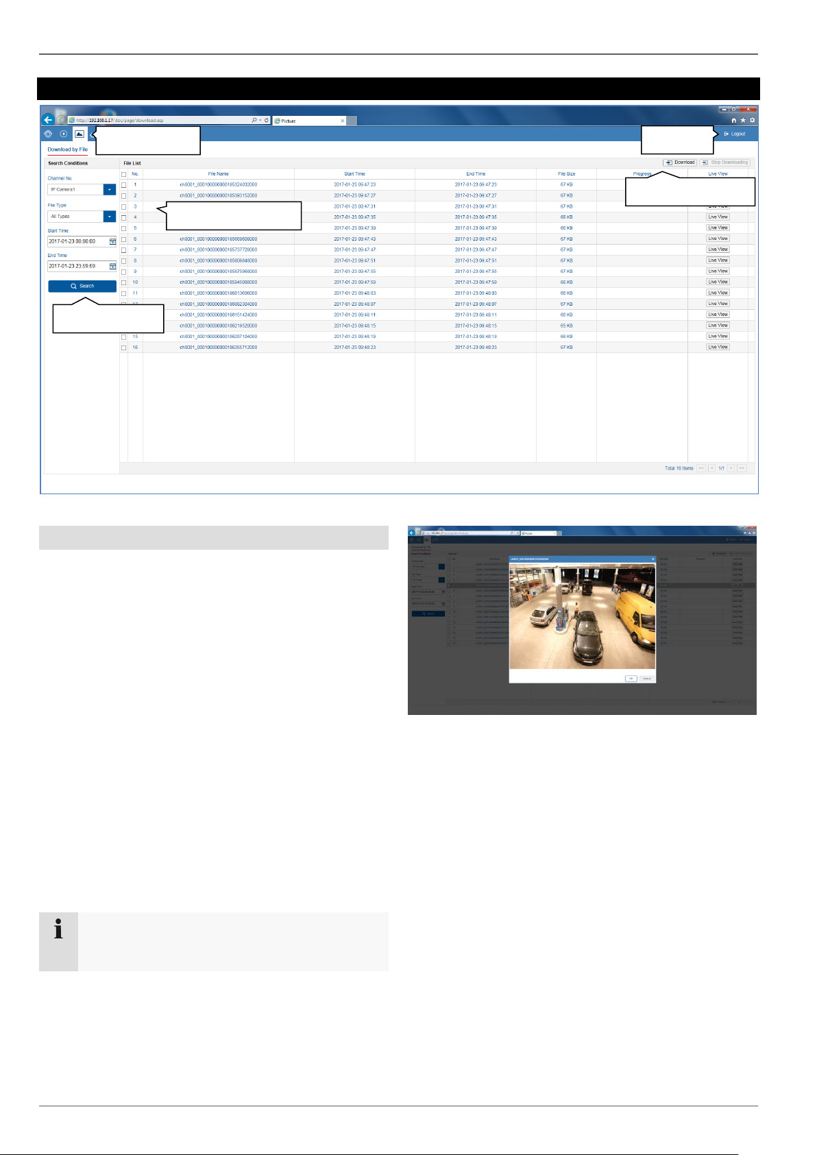
Image export
20
Image export
Image export
You can download the stored snapshot data from the
recorder hard disk drive directly to your PC from here.
Select one or more files and click the "Download" button
to start the data transfer.
There are several filter options available to narrow down
the result list of image files:
Channel number (camera selection)
File type (event selection)
Start time
End time
The default path for exported files is:
C:\Users\[USERNAME]\Web\
[USERNAME] is the name of the Windows user under
which the web interface is run.
Note
You can freely change the settings for the export
path under "Settings Local".
Click on the "Live cast" button to display a preview of the
snapshot file.
Start download
Menu bar
Logout
Define filters
Select data
Page 95
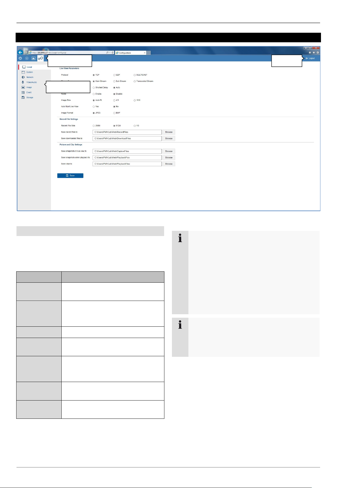
Settings
21
Settings
General settings
The recorder system is configured in the "Settings" menu.
The settings dialogues are divided into the following
areas:
Menu
Description
Local
Configure local (PC-linked) browser
settings
System
Display system information, firmware
update, camera and user
management
Network
Configure TCP/IP and email settings
Audio & video
Configure camera stream for
resolution, bit rate and audio
Image
Menu for configuring OSD
parameters and basic image settings
(brightness etc.)
Event
Configure camera event settings
(motion, VCA, I/O, etc.)
Storage
Menu for configuring recording
parameters (time schedules)
Note
Some of the functions described in this manual
may not be available for your recorder (e.g.
monitor outputs), depending on the model.
New functions may be added or additional
parameters may be added to settings through
subsequent firmware updates.
You can find the valid firmware version number to
which these instructions refer on the cover sheet
of the manual.
Note
The settings for network, audio & video, image,
event and storage are already described in the
basic manual (for the local interface) and are
therefore not explained here.
Menu bar
Logout
Configuration
Page 96

Setting: Local
22
Setting: Local
General information on local settings
You can configure the local settings for the browser plugin on your PC in this menu.
Note
The settings provided under "Local" are defined
separately for each PC user. If you access the
web interface from multiple PC systems, the
settings must be defined here for each PC user.
Live cast parameters
Parameter
Description
Protocol
Select the transfer protocol. TCP
offers the fastest transfer.
Stream type
Define the preset for live stream
configuration here. The preset is
always used as the default setting for
live image display.
Play
performance
Define the play performance. Auto is
the recommended setting.
Rules
Activates/deactivates the display of
visual VCA rules in the live image and
playback.
Image size
The setting can force a specific image
format for the live cast. Fixed formats
(4:3/16:9) may generate horizontal or
vertical edges in the image depending
on the signal source and on how the
live cast display is split (2x2, 3x3, etc.)
Remember live
cast
When existing live cast, the current
display (image panel distribution and
positioning of the cameras) is saved.
When live cast is opened again, the
saved display is restored.
Image format
Export format for snapshots
Record file settings
Parameter
Description
File size
Maximum file size for recordings
Action:
Save recordings
to
Path for storing recordings
Action:
Save
downloaded files
to
Path for storing file downloads
Action:
Page 97

Setting: Local
23
Image/clip settings
Parameter
Description
Save snapshots
in live cast to
Path for storing snapshots from live
cast
Action:
Save snapshots
during playback
to
Path for storing recordings
Action:
Save clips to
Path for storing file downloads
Action:
Page 98

Setting: System
24
Setting: System
General information on system
General system information can be displayed in this
menu, and firmware updates can be carried out. The
system management also contains the camera and user
management.
System settings
Overview
Parameter
Description
Device name
Change the device name here.
No. Change the device ID here. This ID
is used for control via the
TVAC26000 keypad.
Further
information
Display the model IDs and firmware
versions.
Time settings
Parameter
Description
Time zone
Select the time zone in which the
recorder is installed here. The time is
changed by the GMT zone based on
your selection.
NTP
Time synchronisation via the network
using the NTP server.
Important: The NTP time does not
recognise time zones, so the time
zone must be adjusted every time.
Server address
URL/host name of the NTP server
NTP port
Service port of the NTP server
Interval
Update interval for time
synchronisation.
Manual time
synchronisation
Manual time setting
Device time
Current time set on the recorder
Set time
Enter the desired time manually
here.
Synchronisation
with computer
time
Synchronise the time with your PC
time (set time of the operation
system).
DST
Activate DST (Daylight Saving
Time). DST is required for
programming the summer/winter
time setting. The setting is the same
for all regions within Europe.
Page 99

Setting: System
25
Start time
Enter the start time.
Europe: last Sunday of March at
02:00
End time
Enter the end time.
Europe: last Sunday of October at
03:00
DST bias
Relative deviation between the start
and end time. Europe: 60 minutes
Output menu
Parameter
Description
VGA/HDMI
resolution
Configure the resolution of the local
video VGA/HDMI 1 output on the
recorder here.
VGA2/HDMI2
resolution
Configure the resolution of the local
video VGA/HDMI 2 output on the
recorder here.
Maintenance
Upgrade and maintenance
Parameter
Description
Reboot
Carry out a manual restart.
Default
Reset the recorder back to its default
factory settings.
Export
Export the device configuration and
network camera lists (programmed
cameras).
Import
Import the device configuration and
network camera lists (programmed
cameras).
Update
Perform a firmware update.
Protocol
Parameter
Description
Filter1
Select "All" or choose a targeted
filter type. Different parameters for
Filter2 are available depending on
the selection.
Filter2
Detailed filter depending on the
Filter1 selection
Start time
Set the start time
End time
Set the end time
Export
Export event report
Use the report function to get more information about the
system if problems occur.
Camera management
New network cameras can be added to the recorder in
camera management, and the network configuration of
existing cameras can be edited.
Add manually
Press the "Add" button to add a camera manually. You
must know the required network parameters of the
camera you wish to add.
Note
Use the ABUS IP installer to search for cameras
on your network. You can determine the
necessary parameters with this tool.
Describe the required parameters to successfully
program a camera on the recorder.
Add
manually
Add with
network
Page 100

Setting: System
26
Parameter
Description
Address
Enter the IP address of the network
camera here.
Example: 192.168.0.5
Management
protocol
Select the device-specific camera
protocol used to establish
communication between the recorder
and the camera. Here, you can
select the software interface (API),
which may differ depending on the
manufacturer. For ABUS cameras,
choose "ABUS".
Port
Specify the management port which
is used to establish the connection
between the camera and recorder.
For ABUS cameras, use port 8000 or
80.
User name
Enter the user name for the
administrator account for the
camera.
Password
Enter the password for the
administrator account for the camera.
Confirm
Re-enter the password.
Transfer
protocol
Select the transfer protocol.
Quick add
The "quick add" function prompts the recorder to first
attempt to detect all available cameras on the network,
before automatically adding them.
Select one or more cameras in the "Quick add" dialogue
using the button in the first column. When you confirm
with "OK", the recorder attempts to add these cameras as
described above.
Custom protocol
You can create a custom RTSP profile here, which can
then be assigned to a camera in the "Edit" menu.
Note
In order to add cameras with the "quick add"
function, the selected cameras must use the
factory settings for the network port and user
name/password. If these parameters have already
been changed on the camera, the camera can still
be added, but the changed settings must be
adapted later in the "Camera management" menu
using the "Edit" button.
 Loading...