

Page 1
myPCLab
ABUS TECHNOLOGIES INC.
Data Logger
User Manual
Page 2

WARNING
This manual should be passed on to the end user.
The contents of this manual are subject to change without prior notice.
All rights reserved.
ABUS gives no warranty of any kind with regard to this manual, including, but not limited to, fitness
for a particular purpose.
If any question arises or errors are found, or if any information is missing from this manual, please
myPClab
inform your supplier or inform at info@abustek.com
.
The specifications mentioned in this manual are limited to those for the standard type under the
specified model number break-down and do not necessarily apply for customized instruments.
Please note that changes in the specifications, construction, or component parts of the instrument
may not immediately be reflected in this manual at the time of change.
If the customer or any third party is harmed by the use of this product, ABUS assumes no
responsibility for any such harm owing to any defects in the product which were not predictable, or
for any indirect damages.
Although Warning hazards are related to personal injury, and Caution hazards are associated
with equipment or property damage, it must be understood that operation of damaged equipment could,
under certain operational conditions, result in degraded process system performance leading to
personal injury or death. Therefore, comply fully with all Warning and Caution notices.
Information in this manual is intended only to assist our customers in the efficient operation of
our equipment. Use of this manual for any other purpose is specifically prohibited and its contents are
not to be reproduced in full or part without prior approval of Technical Communications Department,
ABUS Technologies
HEALTH AND SAFETY
To ensure that our products are safe and without risk to health, the following points must be
noted:
1. The relevant sections of these instructions must be read carefully before proceeding.
2. Warning labels on containers and packages must be observed.
3. Installation, operation, maintenance and servicing must only be carried out by suitably trained
personnel and in accordance with the information given. Any deviation from these instructions will
transfer the complete liability to the user.
4. Normal safety precautions must be taken to avoid the possibility of an accident occurring when
operating in conditions of high pressure and/or temperature.
5. Chemicals must be stored away from heat, protected from temperature extremes and powders kept
dry. Normal safe handling procedures must be used.
6. When disposing of chemicals ensure that no two chemicals are mixed.
Safety advice concerning the use of the equipment described in this manual or any relevant hazard data
sheets (where applicable) may be obtained from the Company address on the back cover, together with
servicing and spares information.
ABUS TECHNOLOGIES INC.
2
Page 3

myPClab
.
CATALOGUE
Contents Page No.
1. Introduction 4
2. Presentation
Technical Parameters
4
4
3. Dimensions 5
4. Connections
1.
Pt-100 Wiring
Thermocouple Wiring
2.
3. 4 ~ 20 mA Wiring
4.
0 ~ 50 mV Wiring
0 ~ 10 V Wiring
5.
6.
Dry Contact Wiring
Voltage Digital Input Wiring
7.
5. Installation
1. Recommendation
2. Input Signal
3. USB Driver Installation
4.
Software Installation
6. Configuration
Serial Port Assignment
6
6
6
7
7
7
7
8
8
8
8
9
10
11
11
7. Safety Precautions 12
8. Warranty 12
ABUS TECHNOLOGIES INC.
3
Page 4

1. INTRODUCTION
myPCLab is a very compact Data Acquisition tool that connects to a PC via a
USB port and monitors two universal input analogue variables along with one digital
input. From hobbyists to scientists, from simple technical tasks to complex engineering
activities, myPCLab can be an invaluable tool for on-line monitoring and data logging
in school, laboratory research, machine data recording and industrial understanding.
It comes with intuitive and easy-to-use Windows software which plots and
records the data, shows gauges, bar-graphs and digital readouts. The USB port is
accessed as a virtual serial port, which makes myPCLab compatible with SCADA
software with Modbus RTU driver or with any program with ASCII serial
communication.
myPClab
Multiple units of myPCLab can be connected to the same computer, easily
expanding the number of inputs. The myPCLab software can simultaneously
communicate with multiple modules.
This manual describes software installation and connection of input signals to a
myPCLab module. Instructions on using the software are available on its help system.
2. PRESENTATION
Technical Parameters
Analog Input Signals: Configurable for channels 1 and 2. The input signals and measuring ranges are
listed in the above table.
Thermocouples: J, K, T, E, N, R, S and B types.
Input Impedance >> 1 MΩ
Pt100: Three wires connection, 625 A bias current, α = 0.00385.
Linear Signals: 0 to 50 mVdc: Input Impedance >> 1 MΩ
0 to 10 Vdc: Input Impedance = 1 MΩ. Available only for channel 1.
4 to 20 mAdc: Input Impedance: 22 Ω (+ 2,0 Vdc)
Digital Input: Logic voltage or dry contact signals.
“0” Logic Level: contact closed or voltage lower than 0,5 Vdc.
“1” Logic Level: contact opened or voltage from 2,0 V to 5,0 Vdc.
Digital input special features: Digital input can be configured for counting, timing or frequency
measuring (pulses per time unit). Configurable: debounce time and scale
factor.
ABUS TECHNOLOGIES INC.
4
Page 5

Counting: It counts from 0 up to 4294967295. It is selectable to count on input rising
edge, falling edge or both. Maximum input frequency: 1 kHz (square wave,
no debounce). Maximum input frequency: 1 kHz (square wave, no
debounce).
Timing: It times up to 4294967295 milliseconds (more than 49 days). It is
selectable to run timing when input in logic level "0" or when in "1".
Accuracy: 0.5 % of the indicated time.
Frequency: It counts the number of pulses (rising edge, falling edge or both) in each
base time, configurable from 1 to 65535 seconds (18 hours). Maximum
input frequency: 500 Hz (square wave, no debounce). Maximum input
frequency: 500 Hz (square wave, no debounce). Accuracy: 0.5 %.
Ambient Temperature Sensor: Internal thermistor.
Total Accuracy: Thermocouples R, S and B: 0.25% of the maximum range ± 3 °C (with
maximum A/D resolution);
Other thermocouples: 0.25% of the maximum range ± 1 °C (with
maximum A/D resolution);
Pt100, voltage and current: 0.20% of the maximum range (with maximum
A/D resolution);
Ambient temperature channel: ± 1.5 °C (after 20 minutes connected to the
USB port).
A/D Resolution: Configurable from 15 to 11 bits.
Input Sampling Rate: From 8 to 128 samples per second, depending on configured A/D
resolution and number of enabled channels.
Computer Interface: USB V1. 1 Plug and Play, virtual serial port interface.
USB connection: Mini-B receptacle.
Power supply: From the USB bus. Typical current 30 mA.
Operating environment: 0 to 50°C, 10 to 90% relative humidity, non-condensing.
Electromagnetic Compatibility: EN 50081-2, EN 50082-2.
Built-in cold junction compensation for thermocouples and wire resistance for Pt100.
myPClab
ABS case, dimensions: 70 x 60 x 18 mm.
3. DIMENSIONS
ABUS TECHNOLOGIES INC.
5
Page 6
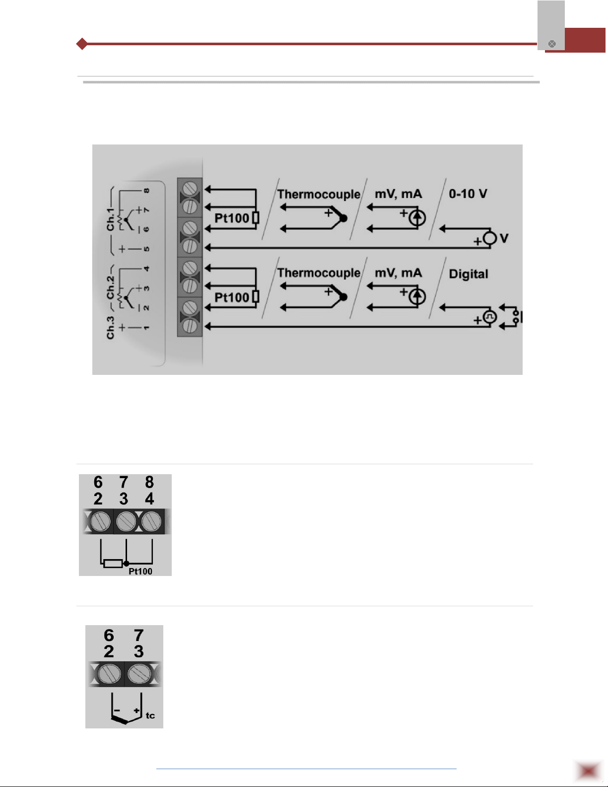
4. CONNECTIONS
This module operates only when connected to a PC USB bus, using the
included type-A to mini-B cable. The following figure shows all possible input
connections.
myPClab
Warning: Signal wires connected to all inputs should be kept separated from power
wires, and when possible installed inside of grounded electrical ducts.
3.1 Pt100 Wiring
Connections of channel 1 are on terminals 6, 7 and 8. For channel 2
on terminals 2, 3 and 4. Connection with 3 wires from the sensor element to the
module is necessary to cancel the cable resistance error in the measurement.
The 3 wires must have the same length and gauge. To connect a Pt100 with 2
wires, connect terminals 7 and 8 (channel 1) or 3 and 4 (channel 2).
3.2 Thermocouple Wiring
Connections of channel 1 are on terminals 6 and 7. For channel 2 on
terminals 2 and 3. Observe indicated polarity. Cables for thermocouple
connection must have the same thermo-electrical characteristics of the
thermocouple element (compensation or extension cable). Observe that both the
thermocouple and the compensation cable must be connected with correct
polarity. If compensation cable is not used or is not connected with the correct
polarity, large measurement errors will arise.
ABUS TECHNOLOGIES INC.
6
Page 7
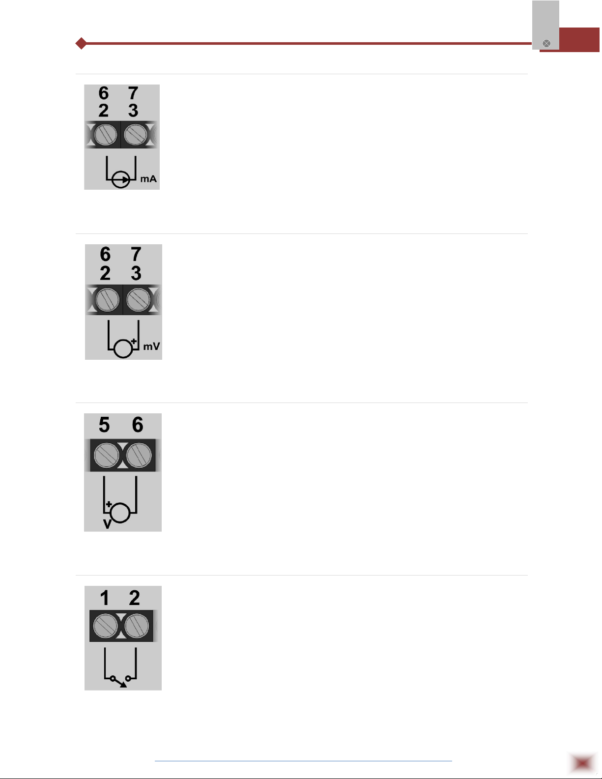
3.3 4-20 mA Wiring
3.4 0-50 mV Wiring
Connections of channel 1 are on terminals 6 and 7. For channel 2 on
terminals 2 and 3. Observe indicated polarity.
Connections of channel 1 are on terminals 6 and 7. For channel 2 on
myPClab
terminals 2 and 3. Observe indicated polarity.
3.5 0-10 V Wiring
Linear voltage signals from 0 to 10 V can only be connected to
channel 1, terminals 5 and 6. Observe indicated polarity.
3.6 Dry Contact Digital Input Wiring
Digital signals are connected to channel 3, terminals 1 and 2.
The contact connected to digital input must not have any electrical voltage.
ABUS TECHNOLOGIES INC.
7
Page 8

3.7 Voltage Digital Input Wiring
Digital signals are connected to channel 3, terminals 1 and 2. Observe
indicated polarity. Voltage levels applied to this channel must be within the
specified limits. See “Technical Parameters”.
5. INSTALLATION
5.1 Recommendation
myPCLab inputs are not electrically isolated from the USB port. Before connecting
myPClab
signals from sensors or transducers, make sure that they are not in contact with any source of
electrical power (wires or conductive surfaces which may get energized). Input channels are not
isolated from each other.
5.2 Input Signal
INPUT TYPE MAXIMUM RANGE
J Thermocouple
K Thermocouple
T Thermocouple
E Thermocouple
N Thermocouple
R Thermocouple
S Thermocouple
-130,0 to 940,0 °C (-202,0 to 1724,0 ºF)
-200,0 to 1370,0 °C (-328,0 to 2498,0 ºF)
-200,0 to 400,0 °C (-328,0 to 752,0 ºF)
-100,0 to 720,0 °C (-148,0 to 1328,0 ºF)
-200,0 to 1300,0 °C (-328,0 to 2372,0 ºF)
0,0 to 1760,0 °C (-32,0 to 3200,0 ºF)
0,0 to 1760,0 °C (-32,0 to 3200,0 ºF)
B Thermocouple
Pt100 RTD
0 to 50 mVdc Adjustable from -32767 to +32767
0 to 10 Vdc (Channel 1) Adjustable from -32767 to +32767
4 to 20 mAdc Adjustable from -32767 to +32767
myPCLab module sensors and signals
ABUS TECHNOLOGIES INC.
500,0 to 1800,0 °C (932,0 to 3272,0 ºF)
-200,0 to 650,0 °C (-328,0 to 1202,0 ºF)
8
Page 9

5.3 USB Driver Installation
The following installation steps may be slightly different depending on your PC
configuration and Windows version. Follow the Wizard instructions and use the
following steps and figures to select the correct installation options.
1. Insert the myPCLab CD in the CD-ROM drive.
2. Connect the module to a PC USB port. Windows® will detect the new hardware
and after a few seconds the new hardware wizard will start.
3. The Found New Hardware Wizard will show-up and ask if you want to connect to
Windows Update to get the driver. Select the “No, not this time” and select “Next”.
4. Select “Install from a list or specific location (advanced)” and select “Next”.
myPClab
5. Select “Search for the best driver in these locations” and check option “Search
removable media”. Select “Next”. If the installation files are not in a CD, select
option “Include this location in the search” and type the path for the required files.
6. If a warning message regarding Windows® XP compatibility appears, select
“Continue Anyway”.
7. The myPCLab driver files will be copied to your computer and, when concluded,
a window will show up informing that the wizard has finished installing the
software. Select “Finish”.
8. It is possible that the previous steps repeat a second time for the completion of
installation.
After driver installation, proceed to the next chapter to install the myPCLab
software that provides configuration, visualization, recording and data export.
In future connection of myPCLab modules, it is possible that Windows® prompt
again for the USB driver installation. In this case, the same wizard will be presented.
Follow the above steps, but select option “Install the software automatically
(recommended)”, since the driver files are already installed.
The following figures are examples of Windows XP® New Hardware Wizard. For
Windows 2000® they look different, but the information is the same.
ABUS TECHNOLOGIES INC.
9
Page 10

PCLab
myPClab
5.4 Software Installation
The my
Configuration of myPCLab modules.
Plot and record data, show gauges, bar-graphs and digital readouts
with data from multiple modules.
Export acquired data in multiple file formats (xls, pdf, rtf, xml, html,
dbf, txt, csv).
To install, execute file myPCLabSetup.exe from the installation CD, and
follow the instructions to proceed with installation.
The myPCLab software has a complete help system, with all the
necessary information for its use. Start the software and press F1 or
select the Help menu to show the help content.
software is a Windows program intended to:
The myPCLab software can simultaneously communicate with multiple
modules, making easy to expand the number of inputs of a measurement system.
ABUS TECHNOLOGIES INC.
10
Page 11

6. CONFIGURATION
Serial Port (COM Port) Assignment
A few seconds after connection of a myPCLab, Windows operating system assigns a COM port
number for communication. The assigned COM port number will not change in future connections to the
same USB port. Users can easily identify and modify the assigned COM port in:
Control Panel / System / Hardware / Device Manager / Ports (COM & LPT)
Select the desired “myPCLab” device, click with the right mouse button and select “Properties”.
Select “Port Settings” and click on the “Advanced...” button. In “COM Port Number” list, select the serial
port to be assigned. Some serial port can be marked as “in use”. Only select one of these ports if you
are sure it is not being used by any other peripheral in your computer.
In some cases, serial port can be marked as “in use” even when the associated device is not in
the computer. In this case, it is safe to assign this port to myPCLab.
myPClab
The following figures illustrate the most important steps for this procedure.
ABUS TECHNOLOGIES INC.
11
Page 12

7. SAFETY PRECAUTIONS
1. The unit should be powered for 15 minutes before use.
2. Use in ambient temperature of 0-60˚C.
3. Avoid vibrations, shock, excessive dust, corrosive chemical materials or gaseous
environment.
4. Input wire should not be too long. If measured signal have to be far away from the
unit, please use 2-core shielded cable.
5. Use this instrument in the scope of its specifications, otherwise fire or malfunctions
may result.
6. Contact of the instrument, with organic solvents or oils should be avoided.
7. Do not turn on the power supply until all of the wiring is completed. Otherwise
myPClab
electrical shock, fire or malfunction may result.
8. Do not disassemble, repair or modify the instrument.
9. All connections should be tightened properly.
10. Power supply should be constant, should not be fluctuating.
8. WARRANTY
ABUS provides the original purchaser of this instrument a one (1) year warranty
against defects in material and workmanship under the following terms:
The one year warranty begins on the day of shipment as stated on the sales bill.
During the warranty period all costs of material and labor will be free of charge
provided that the instrument does not show any evidence of misuse.
For maintenance, return the instrument with a copy of the sales bill to our factory.
All transportation and insurance costs should be covered by the owner of the
equipment.
Should any sign of electrical or mechanical shock, abuse, bad handling or misuse
be evident the warranty voids and maintenance costs will be charged.
ABUS TECHNOLOGIES INC.
www.abustek.com, E-M ail: info@abustek.com
ABUS TECHNOLOGIES INC.
12
 Loading...