

Page 1
ABUS TECHNOLOGIES INC.
New
MG
Low Differential Pressure Gauge
User Manual
Page 2

WARNING
This manual should be passed on to the end user.
The contents of this manual are subject to change without prior notice.
All rights reserved.
ABUS gives no warranty of any kind with regard to this manual, including, but not limited to, fitness
for a particular purpose.
If any question arises or errors are found, or if any information is missing from this manual, please
MG
inform your supplier or inform at info@abustek.com
The specifications mentioned in this manual are limited to those for the standard type under the
specified model number break-down and do not necessarily apply for customized instruments.
Please note that changes in the specifications, construction, or component parts of the instrument
may not immediately be reflected in this manual at the time of change.
If the customer or any third party is harmed by the use of this product, ABUS assumes no
responsibility for any such harm owing to any defects in the product which were not predictable, or
for any indirect damages.
Although Warning hazards are related to personal injury, and Caution hazards are associated
with equipment or property damage, it must be understood that operation of damaged equipment could,
under certain operational conditions, result in degraded process system performance leading to
personal injury or death. Therefore, comply fully with all Warning and Caution notices.
Information in this manual is intended only to assist our customers in the efficient operation of
our equipment. Use of this manual for any other purpose is specifically prohibited and its contents are
not to be reproduced in full or part without prior approval of Technical Communications Department,
ABUS Technologies
.
HEALTH AND SAFETY
To ensure that our products are safe and without risk to health, the following points must be
noted:
1. The relevant sections of these instructions must be read carefully before proceeding.
2. Warning labels on containers and packages must be observed.
3. Installation, operation, maintenance and servicing must only be carried out by suitably trained
personnel and in accordance with the information given. Any deviation from these instructions will
transfer the complete liability to the user.
4. Normal safety precautions must be taken to avoid the possibility of an accident occurring when
operating in conditions of high pressure and/or temperature.
5. Chemicals must be stored away from heat, protected from temperature extremes and powders kept
dry. Normal safe handling procedures must be used.
6. When disposing of chemicals ensure that no two chemicals are mixed.
Safety advice concerning the use of the equipment described in this manual or any relevant
hazard data sheets (where applicable) may be obtained from the Company address on the back cover,
together with servicing and spares information.
ABUS TECHNOLOGIES INC.
2
Page 3
1. Introduction
4
MG
.
CATALOGUE
Contents Page No.
2. Presentation
1 Features
2 Technical Parameters
3. Dimensions 5
4. Ordering details 6
5. Connections
1. Positive Pressure Measurement
2. Negative Pressure Measurement
3. Differential Pressure Measurement
6. Installation
1 Recommendation
2 Surface Mounting
3 Flush or Panel Mounting
7. Safety Precautions 9
8. Warranty 9
Applications
4
4
4
5
7
7
7
7
7
7
7
8
ABUS TECHNOLOGIES INC.
3
Page 4

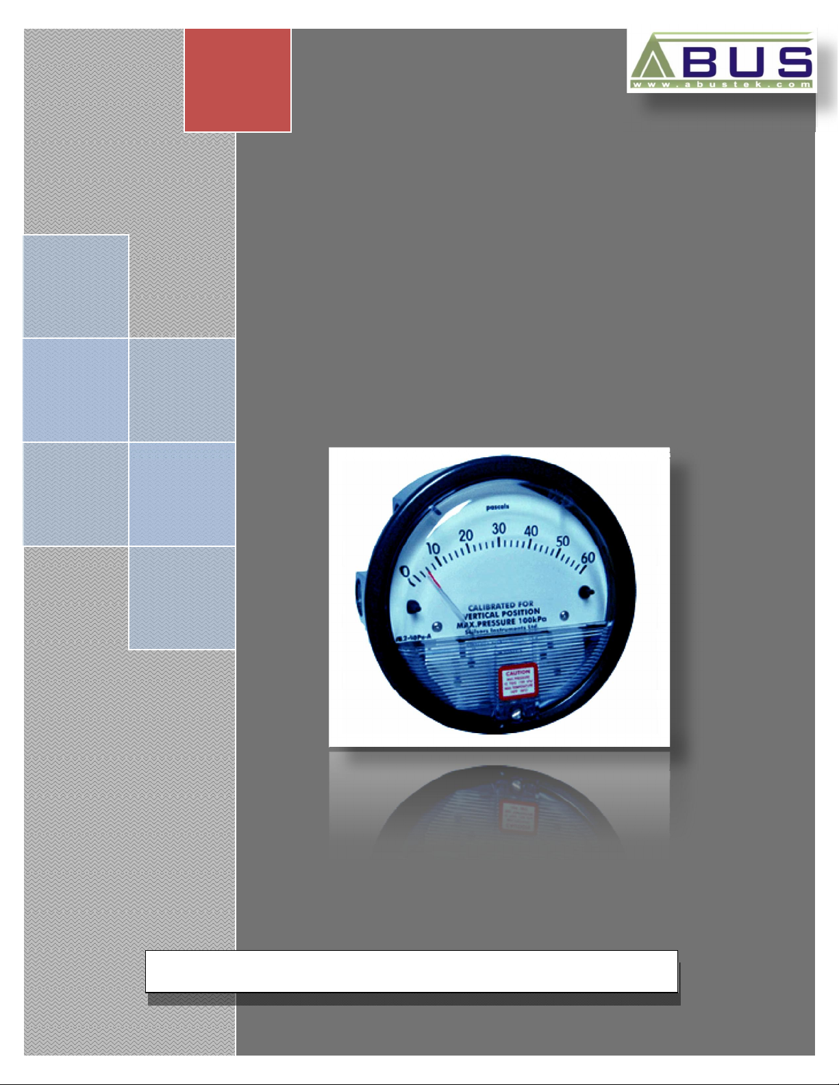
1. INTRODUCTION
The magnet-helix type gauges are designed to give fast, accurate indication of
differential pressures. The gauge may be served as a readout device when measuring
fluids (Air and non-combustible, compatible gases). Guaranteed within 2% of full scale
– and for the wide choice of 81 ranges available to precisely suit your needs. A simple,
frictionless movement, which caused by pressure difference, forces the magnetic helix
to turn in order to maintain the gap and the pointer fixed to the helix turns accordingly.
It quickly indicates low air or non-corrosive gas pressures – positive, negative or
differential. This design resists shock, vibration and over-pressures. No manometer
MG
fluid to evaporate, freeze or cause toxic or leveling problems.
Applications
The MG are designed to measure positive, negative, or differential pressure of low air and non-
corrosive gases with a full span accuracy of 2% at a competitive price. They are widely used for filter
condition checks, HVAC control, and the measurement of fan and blower pressures, air velocity, and
pressure drop across orifice plates applications, as well as other applications in the pharmaceutical and
semiconductor manufacturing industry.
2. PRESENTATION
2.1 Features
1. Magnet-helix indicating mechanism ideal for low DP measurement
2. A wide selection of ranges from 0Pa to 60Pa at up to 2.5KPa
3. Accuracy 2% of FS
4. Inertia-free, drift-free pointer indication
5. OEM solutions available
ABUS TECHNOLOGIES INC.
4
Page 5
2.2 Technical Parameters
Service: Air and non-combustible, compatible gases
Ranges: Refer Ordering Table below.
Accuracy: ±2% of full span at 21°C (±3% on MG-0.50IN, MG/Z-0.5IN, MG-
10MM, MG-100Pa, MG-125Pa and ±4% on MG-0.25IN, MG-6MM,
MG-60Pa ranges).
Ambient Temperature: -7 ~ 60°C
Pressure Limit: -68 ~ 100KPa
Overpressure: Relief plug opens at approximately 25Psig (172KPa)
Process Connections: 1/8″ female NPT duplicate high and low pressure taps: one pair side
and one pair back
Case and Bezel Material: Die cast aluminum
Weight: 460g
Dial Size: 4″ Diameter
MG
Mounting Position: Vertical
Standard Accessories: Two 1/8″ NPT plugs for duplicate pressure taps, two 1/8″ pipe thread
to rubber tubing adapter, and three flush mounting adapters with
screws.
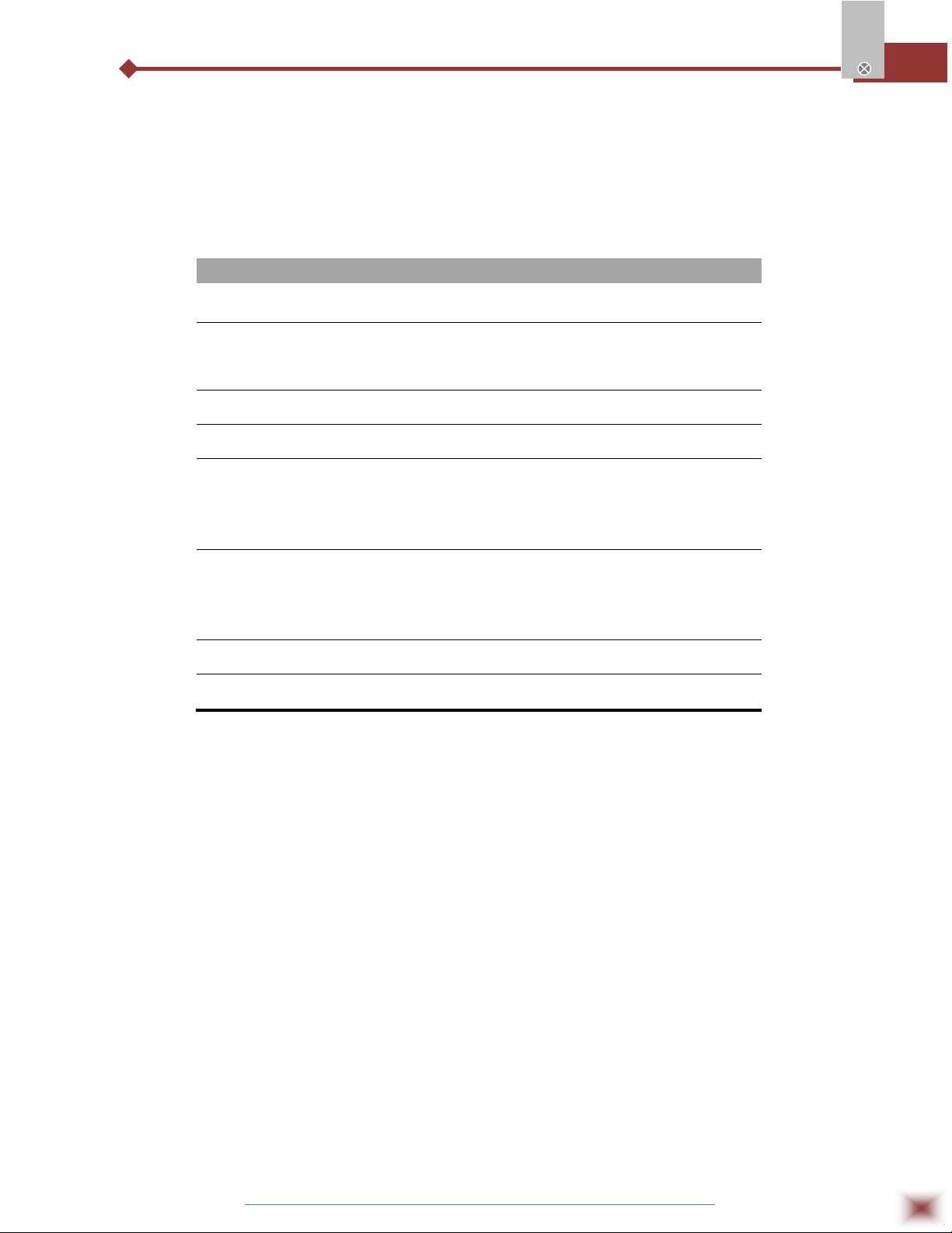
3. DIMENSIONS
All Dimensions in mm
ABUS TECHNOLOGIES INC.
5
Page 6

4. ORDERING DETAILS
Model No.
MG-0.25IN**
MG-0.50IN*
MG-1.0IN
MG-2.0IN
MG-3.0IN
MG-4.0IN
MG-5.0IN
MG-6.0IN
MG-8.0IN
MG-10IN
MG-15IN
MG-20IN
MG-25IN
MG-30IN
MG-40IN
MG-50IN
MG-60IN
MG-80IN
MG-100IN
MG-150IN
Range
(inH2O)
0-0.25
0-0.50
0-1.0
0-2.0
0-3.0
0-4.0
0-5.0
0-6.0
0-8.0
0-10
0-15
0-20
0-25
0-30
0-40
0-50
0-60
0-80
0-100
0-150
MG/Z-0.5IN*
MG/Z-1.0IN
Model No.
MG/Z-2IN
MG/Z-4IN
MG/Z-10IN
MG/Z-20IN
MG/Z-30IN
Model No.
MG-1PSI
MG-2PSI
MG-3PSI
MG-4PSI
MG-5PSI
MG-10PSI
MG-15PSI
MG-20PSI
MG-30PSI
Range Zero
Center
(inH2O)
0.25-0-0.25
0.5-0-0.5
1-0-1
2-0-2
5-0-5
10-0-10
15-0-15
Range
(psi)
0-1
0-2
0-3
0-4
0-5
0-10
0-15
0-20
0-30
Model No.
MG-6MM**
MG-10MM*
MG-25MM
MG-50MM
MG-80MM
MG-100MM
Model No.
MG-15CM
MG-20CM
MG-25CM
MG-50CM
MG-80CM
MG-100CM
MG-150CM
MG-200CM
MG-250CM
MG-300CM
MG
Range
(mmH2O)
0-6
0-10
0-25
0-50
0-80
0-100
Range
(cmH2O)
0-15
0-20
0-25
0-50
0-80
0-100
0-150
0-200
0-250
0-300
Model No.
MG-60Pa**
MG-100Pa*
MG-125Pa*
MG-250Pa
MG-300Pa
MG-500Pa
MG-750Pa
Zero Center Ranges
Model No.
MG/Z-250Pa
MG/Z-500Pa
MG/Z-1KPa
MG/Z-3KPa
Range
(Pa)
0-60
0-100
0-125
0-250
0-300
0-500
0-750
Range
(Pa/KPa)
125-0-125
250-0-250
0.5-0-0.5K
1.5-0-1.5K
Model No.
MG-1KPa
MG-1.5KPa
MG-2KPa
MG-3KPa
MG-4KPa
MG-5KPa
MG-8KPa
MG-10KPa
MG-15KPa
MG-20KPa
MG-25KPa
MG-30KPa
Range
(KPa)
0-1
0-1.5
0-2
0-3
0-4
0-5
0-8
0-10
0-15
0-20
0-25
0-30
Model No.
MG/Z-20MM
MG/Z-4CM
MG/Z-10CM
MG/Z-30CM
Dual Scale English/Metric
Model
No.
MG/D-0.5
MG/D-1.0
MG/D-2.0
MG/D-3.0
MG/D-4.0
MG/D-6.0
MG/D-8.0
MG/D-10
Zero Center
2-0-2 cmH2O
5-0-5 cmH2O
Models
Range
(inH2O)
0-0.5
0-1.0
0-2.0
0-3.0
0-4.0
0-6.0
0-8.0
0-10
Range
10-0-10
mmH2O
15-0-15
cmH2O
(Pa/KPa)
Range
0-125
0-250
0-500
0-750
0-1.0
0-1.5K
0-2.0K
0-2.5K
ABUS TECHNOLOGIES INC.
6
Page 7
5. CONNECTIONS
5.1 Positive Pressure Measurement
Connect the pressure tubing to either of the two ports marked “high pressure” on the gage and
plug the other one. Vent the ports marked “low pressure” to atmosphere.
5.2 Negative Pressure Measurement
Connect the pressure tubing to either of the two ports marked “low pressure” on the gage and
plug the other one. Vent the ports marked “high pressure” to atmosphere.
5.3 Differential Pressure Measurement
Connect the higher pressure tubing to either of the two ports marked “high pressure” on the
gage and plug the other one. Connect the lower pressure tubing to either of the two ports marked “low
pressure” on the gage and plugging the other one.
6. INSTALLATION
6.1 Recommendation
Upon receipt please inspect the instrument for the intended application range.
MG
The instrument should be installed in a place where excessive pressure is not present and the
ambient temperature is less than 140°F (60°C).
All standard MG gauges are calibrated in the vertical position. To maintain the specified
accuracy, the gauge must be mounted in the vertical position.
6.2 Surface Mounting
Drill 3 holes spaced equally apart on a 4 1/16" diameter circle to match the holes on the back of
the gauge. Secure the gauge with 3 mounting screws of suitable length provided.
ABUS TECHNOLOGIES INC.
7
Page 8
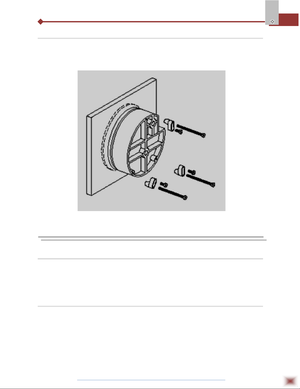
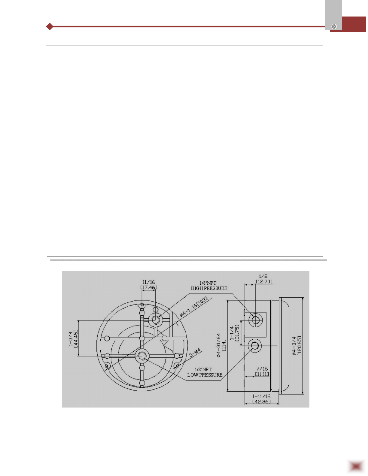
6.3 Flush or Panel Mounting
Cut an opening in the panel 4 9/16" in diameter. Put the gauge in the panel cutout, attach
adapters, and use the 6 mounting screws provided to fasten the gauge in place.
MG
7. CONFIGURATION
7.1 Zero Point Adjustment
Zero adjustment can be made after the installation. Use the zero adjusting screw at the bottom
of the cover to zero the pointer while both the high and low pressure ports are open to atmospheric
pressure.
7.2 Indicating Mechanism
When pressure is applied to both sides of the diaphragm in operation, any difference in pressure
causes the diaphragm, the spring that the diaphragm is linked to, and the magnet attached to the spring
to move. The movement of the magnet forces the magnetic helix to turn in order to maintain the gap,
and the pointer fixed to the helix turns with it.
ABUS TECHNOLOGIES INC.
8
Page 9

8. SAFETY PRECAUTIONS
1. The unit should be powered for 15 minutes before use for electronic device.
2. Use in ambient temperature of 0-60˚C.
3. Avoid vibrations, shock, excessive dust, corrosive chemical materials or gaseous
environment.
4. Input wire should not be too long. If measured signal have to be far away from the
unit, please use 2-core shielded cable.
5. Use this instrument in the scope of its specifications, otherwise fire or malfunctions
may result.
6. Contact of the instrument, with organic solvents or oils should be avoided.
7. Do not turn on the power supply until all of the wiring is completed. Otherwise
MG
electrical shock, fire or malfunction may result.
8. Do not disassemble, repair or modify the instrument.
9. All connections should be tightened properly.
10. Power supply should be constant, should not be fluctuating.
9. WARRANTY
ABUS provides the original purchaser of this instrument a one (1) year warranty
against defects in material and workmanship under the following terms:
The one year warranty begins on the day of shipment as stated on the sales bill.
During the warranty period all costs of material and labor will be free of charge
provided that the instrument does not show any evidence of misuse.
For maintenance, return the instrument with a copy of the sales bill to our factory.
All transportation and insurance costs should be covered by the owner of the
equipment.
Should any sign of electrical or mechanical shock, abuse, bad handling or misuse
be evident the warranty voids and maintenance costs will be charged.
ABUS TECHNOLOGIES INC.
www.abustek.com, E-M ail: info@abustek.com
ABUS TECHNOLOGIES INC.
9
 Loading...