

Page 1
ABUS TECHNOLOGIES INC.
Log Box-AA
Data Logger
User Manual
Page 2

WARNING
This manual should be passed on to the end user.
The contents of this manual are subject to change without prior notice.
All rights reserved.
ABUS gives no warranty of any kind with regard to this manual, including, but not limited to, fitness
for a particular purpose.
If any question arises or errors are found, or if any information is missing from this manual, please
Log Box-AA
inform your supplier or inform at info@abustek.com
.
The specifications mentioned in this manual are limited to those for the standard type under the
specified model number break-down and do not necessarily apply for customized instruments.
Please note that changes in the specifications, construction, or component parts of the instrument
may not immediately be reflected in this manual at the time of change.
If the customer or any third party is harmed by the use of this product, ABUS assumes no
responsibility for any such harm owing to any defects in the product which were not predictable, or
for any indirect damages.
Although Warning hazards are related to personal injury, and Caution hazards are associated
with equipment or property damage, it must be understood that operation of damaged equipment could,
under certain operational conditions, result in degraded process system performance leading to
personal injury or death. Therefore, comply fully with all Warning and Caution notices.
Information in this manual is intended only to assist our customers in the efficient operation of
our equipment. Use of this manual for any other purpose is specifically prohibited and its contents are
not to be reproduced in full or part without prior approval of Technical Communications Department,
ABUS Technologies
HEALTH AND SAFETY
To ensure that our products are safe and without risk to health, the following points must be
noted:
1. The relevant sections of these instructions must be read carefully before proceeding.
2. Warning labels on containers and packages must be observed.
3. Installation, operation, maintenance and servicing must only be carried out by suitably trained
personnel and in accordance with the information given. Any deviation from these instructions will
transfer the complete liability to the user.
4. Normal safety precautions must be taken to avoid the possibility of an accident occurring when
operating in conditions of high pressure and/or temperature.
5. Chemicals must be stored away from heat, protected from temperature extremes and powders kept
dry. Normal safe handling procedures must be used.
6. When disposing of chemicals ensure that no two chemicals are mixed.
Safety advice concerning the use of the equipment described in this manual or any relevant hazard data
sheets (where applicable) may be obtained from the Company address on the back cover, together with
servicing and spares information.
ABUS TECHNOLOGIES INC.
2
Page 3

Log Box-AA
.
CATALOGUE
Contents Page No.
1. Introduction 4
2. Presentation
Technical Parameters
1.
2.
Memory capacity
Input signals
3.
Data acquisition
4.
4
4
5
5
5
3. Dimensions 5
4. Connections
1. IP65 Model
2. IP67/IP68 Model
3. Input Connection
4. External Battery Switch
5. Digital Input
5. Installation
1. Recommendation
2. Input Signal
3.
4.
5.
6.
Panel
LogChat-II
Optic Interface IR-Link3
Palmtop User
6. Configuration
1. General information Field
2. Acquisition Field
3. Start Loggings Field
4. Stop Loggings Field
5. Channels Field
6. Palmtop User
6
6
7
8
8
9
9
9
9
9
10
11
11
12
13
13
14
14
14
15
7. Operation
1. Offloading Data
2. Visualization Data
3. Monitoring Acquisition
4. Palmtop User
8. Maintenance
1. Observation
2. Troubleshooting
19
19
20
21
21
22
22
22
9. Safety Precautions 23
10. Warranty 23
ABUS TECHNOLOGIES INC.
3
Page 4

1. INTRODUCTION
LogBox-AA is an electronic data logger with two analog input channels. Values
measured by these channels (data) are stored in the logger electronic memory
(acquisitions) for later download to a PC for visualization and analysis in the form of
tables or graphs. Data can be easily exported to spreadsheets.
The LogChart-II is the software used to configure the logger, download and
visualize data. The logger configuration allows define the logger operation mode,
including the start/stop time of data acquisition. Other parameters such as signal input
type, Logging interval, etc., are easily selected through the LogChart-II software.
The LogBox-AA also provides a signal for commanding an external power
supply (battery) of a device connected to the logger. This feature allows that external
Log Box-AA
devices, such as a transmitter, be powered only during the measurement sample time,
thus extending the service life of these external batteries.
2. PRESENTATION
2.1 Technical Parameters
Input resistance: 0-50mV, Pt100 and thermocouples: >10MΩ
0-10V: > 1MΩ
0 to 20mA and 4 to 20mA: 100Ω + 2 Vdc
Accuracy: Thermocouple J, K and T: 0.25% of Max. Range ±1°C;
Thermocouple N, R, S, B: 0.25% of Max. Range ±3°C;
Pt100: 0.2% of the Max. Range;
mA, mV and V: 0.2% of the max. Range;
Memory capacity: 32k or 64k loggings.
Interval between readings: Minimum: 10 seconds, maximum: 18 hours
External battery switch time: 3.6V lithium battery (1/2 AA)
Typical battery life: 1 year (one download daily, 5 minutes acquisition interval)
Working temperature: From –40°C to 70°C.
Protection: IP65, IP67 and IP68 models (see lateral label on product)
Material: ABS with polycarbonate film case; Polycarbonate film
Dimensions: 60x70x35mm
ABUS TECHNOLOGIES INC.
4
Page 5
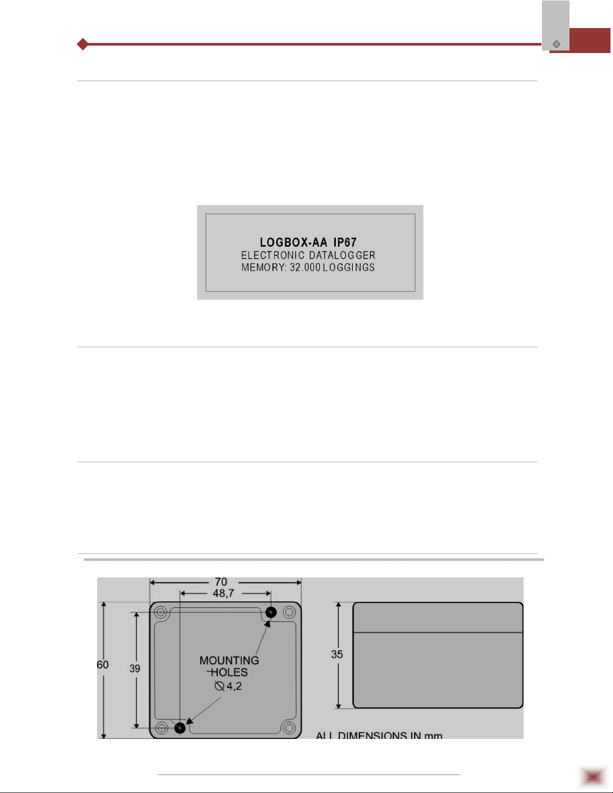
2.2 Memory Capacity
Two memory storage capacities are offered: 32K or 64K records:
32k Model: Allows up to 32,000 records;
64k Model: Allows up to 64,000 records;
Memory capacity is always shared between enabled channels. In case there are two channels
enabled, each gets 50 percent of the memory available. When only a single channel is enabled, it has
the entire memory at its disposal. Memory capacity is indicated on the identification label placed on the
logger case.
Log Box-AA
Identification label
2.3 Input Signals
The input channels 1 and 2 measure analog electric signals, which can be Pt100,
Thermocouple (J, K, T, E, N, R, S or B), voltage (0 to 50 mV or 0 to 10 V) or current (0 to 20mA or 4 to
20mA), according to user-defined settings.
Note: Besides configuration performed through the software, the definition of input signal requires two
internal jumpers to be configured.
2.4 Data Acquisition (logging)
Data can be acquired through different modes. The logger can be configured to perform a
single measurement within a time interval storing the value read or perform ten measurements within
the time interval and store the mean of values measured. Yet, it can store the minimum or maximum
values read in the interval.
3. DIMENSIONS
ABUS TECHNOLOGIES INC.
5
Page 6
4. CONNECTIONS
Only the input connections and the External Battery Switch (when used) are
needed. The logger is exclusively powered by its internal battery. In the IP65 models,
the inputs and the signal for activating the external power supply are located inside the
logger case, which must be opened for accomplishing the connections. In the IP67
and IP68 models, proper connectors are provided for this purpose, as shown in Figure
IP67/IP68 connectors, below.
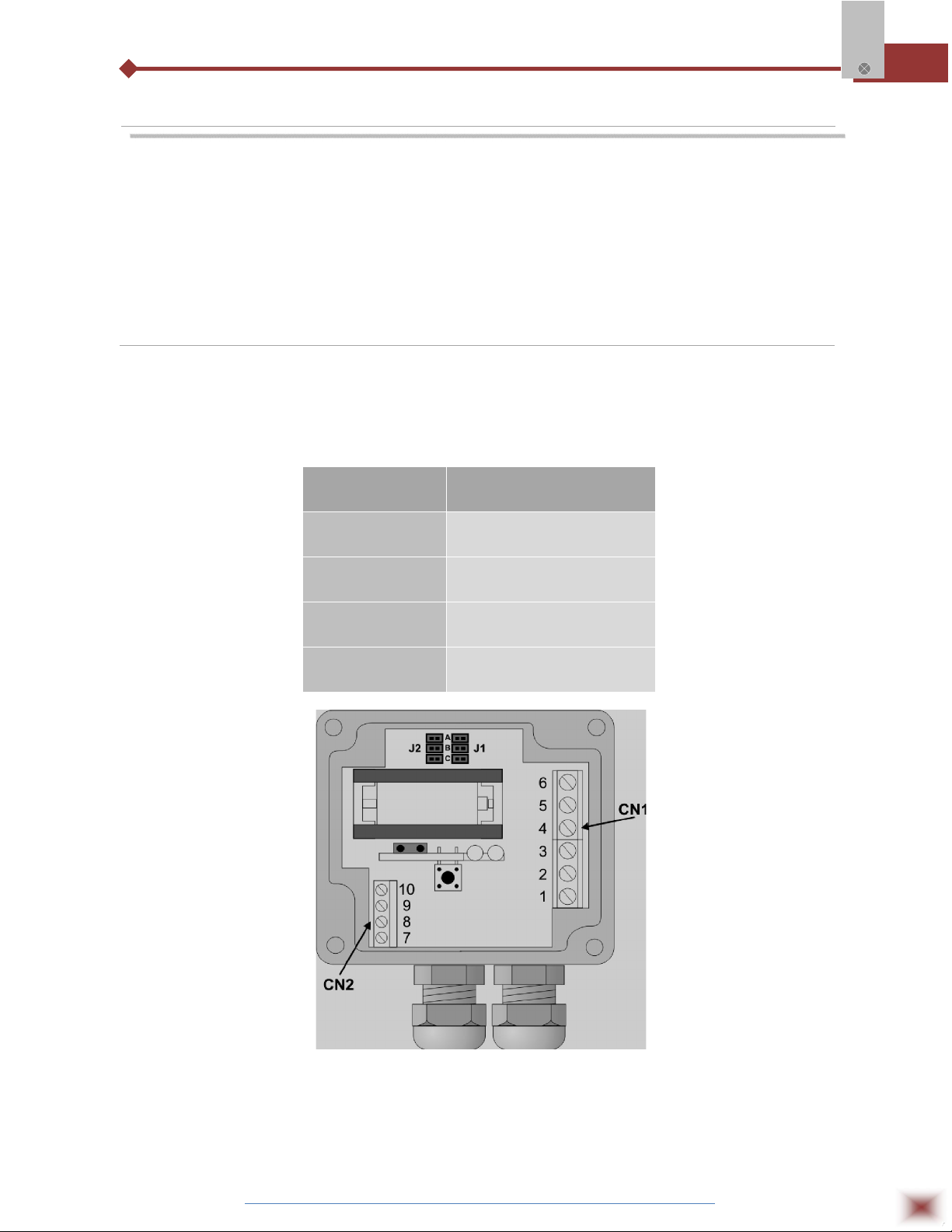
4.1 IP65 Model
Open the logger’s cover to get access to the block terminals and the configuration jumpers. Connection
cables must pass through the compress fitting located at the bottom of the case. Figure IP65
connections internal view, below shows the internal terminals distribution.
Log Box-AA
PARAMETER DESCRIPTION
Channel 1:
Channel 2:
External Battery
Switch
Digital Input
CN1 connector – Terminals
1, 2 and 3
CN1 connector – Terminals
4, 5 and 6
CN2 connector – Terminals
7, 8 and 9
CN2 connector – Terminals
7, 10 and 9
IP65 connections internal view
Note: Make sure that the compress fitting is perfectly tightening the cables, thus assuring proper IP65
protection: (totally dust-tight and protected against water jets).
ABUS TECHNOLOGIES INC.
6
Page 7
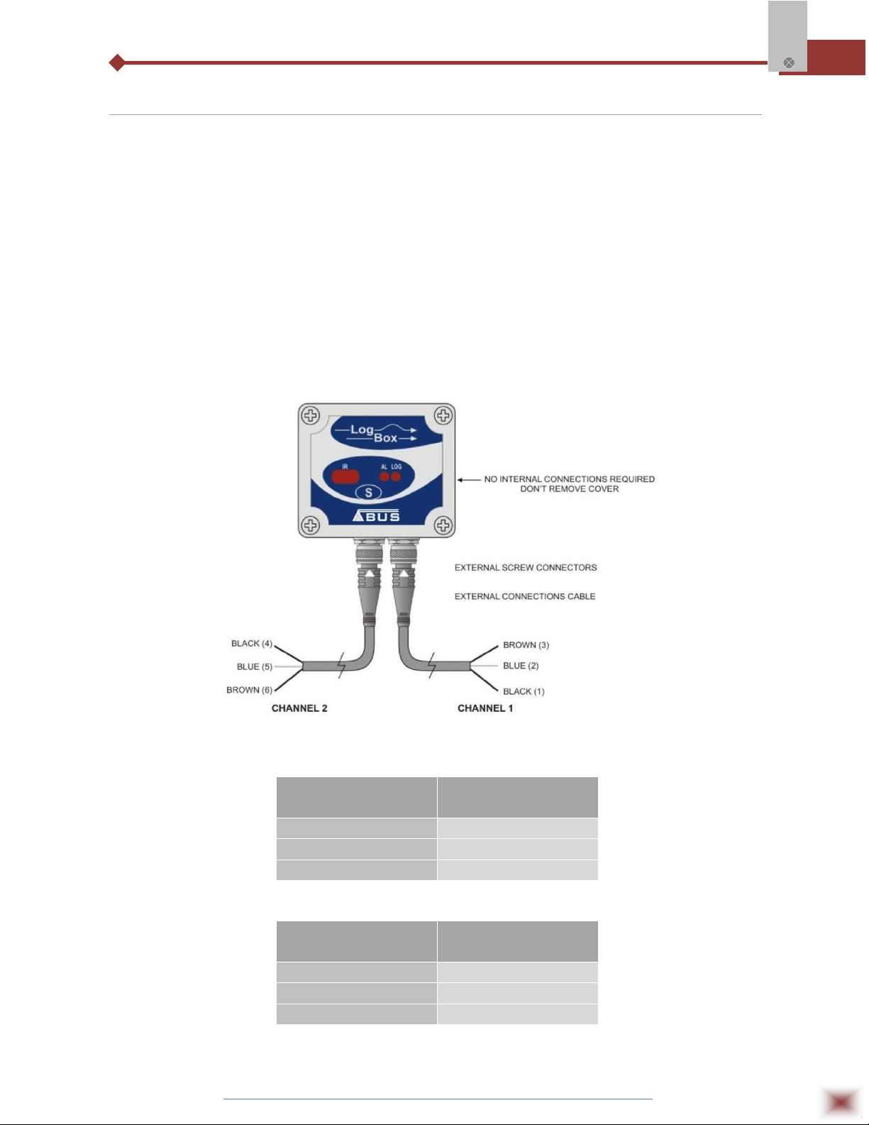
4.2 IP67/IP68 Model
In theIP67/IP68 version, an M8 connector is provided for signal input. Two connectors provide
external access to the input channels, as shown in Figure IP67/IP68 external connectors, below. The
cables are supplied with the logger.
Note: The case cover should not be opened unless battery replacement is required. If this is the case,
the cover must be properly tightened back in its place such as to assure the IP67 / 68 protection.
IP67 - Totally dust-tight and protected from temporary immersion in water.
IP67 - Totally dust-tight and protected from submersion in water.
Log Box-AA
IP67/IP68 external connectors
CHANNEL 1 CABLE
(RIGHT)
CONNECTION
Brown CN1 – 3
Blue CN1 - 2
Black CN1 -1
CHANNEL 2 CABLE
(LEFT)
Brown CN1 -6
Blue CN1 – 5
Black CN1 – 4
ABUS TECHNOLOGIES INC.
CONNECTION
7
Page 8

4.3 Input Connections
Both models have the same input connections schema:
Log Box-AA
Input Signal Connections
Before using the logger, the internal jumpers positioning must be set according to the input type
used. The factory setting of these jumpers is for measurement of Pt100 / Thermocouple / 0-50mV
signals. Figures show some positioning for possible input types.
INPUT SIGNAL
CHANNEL 1
J1 POSITION
CHANNEL 2
J2 POSITION
4-20 mA / 0-20 mA A A
Pt100 / Thermocouple / 0-50mV
B B
0-10V C C
J1 and J2 positioning
4.4 External Battery Switch
The example below shows the usage of the external battery switch for commanding the power
supply of external devices. - Channel 1 is configured to 4-20mA input signal. A battery is used to
provide power to the 4-20 mA loop. The battery switch “turns on” the power to the loop a moment
(defined in the configuration) before the measurement is taken, enabling the transmitter (pressure,
temperature, etc) to start up and stabilize the output.
Example of the battery switch powering a transmitter.
ABUS TECHNOLOGIES INC.
8
Page 9

4.5 Digital Input (DI)
The Digital Input that can be used to guide the logger readings is available in terminals 7 (-) and
10 (+) of CN2.
5. INSTALLATION
5.1 Recommendation
1. Signal wires should be installed in grounded conduits and away from power or contactor wires.
2. Instruments must be powered only by an exclusive power supply.
3. System failure should always be taken into account when designing a control panel to avoid
irreversible damage to equipment or people.
4. Installing RC filters (47R and 100nF, serial) is strongly recommended at contactor coils or any other
inductors.
Log Box-AA
5.2 Input Signal
TYPE CHARACTERISTICS
J Range: -50 to 760 °C (-58 to 1400ºF)
K Range: -90 to 1370 °C (-130 to 2498ºF)
T Range: -100 to 400 °C (-148 to 752ºF)
N Range: -90 to 1300 °C (-130 to 2372ºF)
R Range: 0 to 1760 °C (32 to 3200ºF)
S Range: 0 to 1760 °C (32 to 3200ºF)
B Range: 150 to 1820 °C (32 to 3308ºF)
Pt100 Range: -200.0 to 650.0 °C (-328 to 1202ºF)
0-50mV Linear. Programmable range of -32768 to 32767
4-20 mA Linear. Programmable range of -32768 to 32767
0-20 mA Linear. Programmable range of -32768 to 32767
0-10Vdc Linear. Programmable range of -32768 to 32767
5.3 Panel
The Status Indicators are located in the logger front panel. They indicate the current working
conditions of the unit.
LOG Indicator (Logging): While in stand-by (not logging) or after a series of acquisitions is ended, it
flashes once at every four seconds. During login it flashes twice at every
four seconds.
ABUS TECHNOLOGIES INC.
9
Page 10
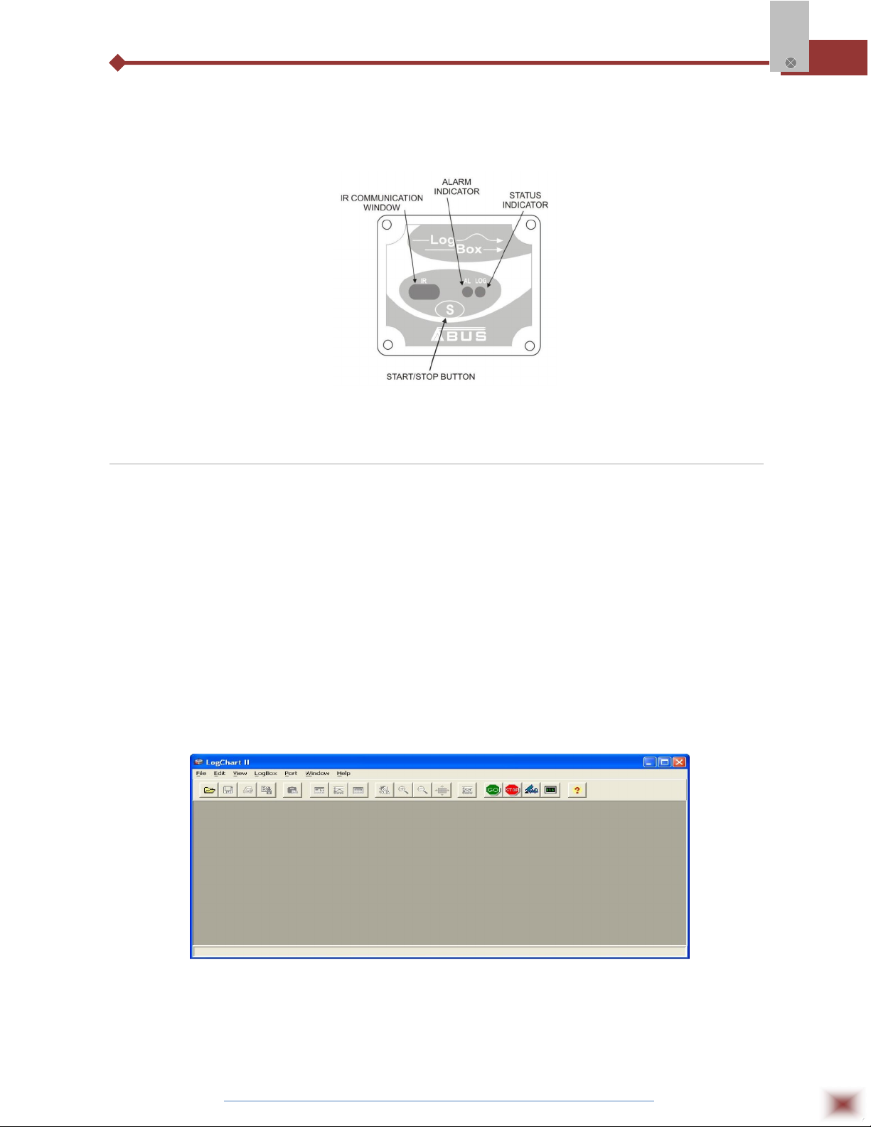
AL Indicator (alarm): Alerts the user regarding alarm conditions. Whenever an alarm situation
takes place it will flash once at every four seconds, until a new configuration
is applied to the logger.
LED Indicators and IR communication
5.4 LogChart-II
5.4.1 INSTALLING LOGCHART-II
The LogChart II is the software provided with the logger to allow for configuration and data
collection. To install the LogChart II, execute the LC_II_Setup.exe program provided in the CD. The
Log Box-AA
installation wizard will then guide you throughout the installation process.
Note: Be sure your Windows date separator is configured as a slash: dd/mm/yy or dd/mm/yyyy.
5.4.2 RUNNING LOGCHART-II
Start the program. The main window will appear on the screen, as shown in Figure below.
LogChart-II main window
The LogChart II requires a communication port to talk to the logger. Select one and connect the
corresponding wand IR-LINK3 to it. Click on the menu Port. Clicking on the menu Port, all free
communication ports available in the computer will be listed (usually COM2, once the mouse is
frequently connected at COM1). The chosen port will be remembered next times the LogChart II is
ABUS TECHNOLOGIES INC.
10
Page 11

initiated. When the selected port is successfully opened, the LogChart II initial screen is opened,
enabling the buttons below:
Log Box-AA
Buttons enabled when the communication port of choice is valid
In case the user wants to stop the process while data logging is running, the button “Stop” must
be pressed:
5.5 Optic Interface IR-Link3
Configuring, monitoring or downloading data from the logger through LogChart-II requires that
the IR-LINK3 communication interface be connected to your PC. This interface is sold separately. The
IR-LINK3 interface sends and receives data to/from the logger through infrared signals.
5.5.1 IR-Link3 for RS232
This interface has a DB9 terminal that must be connected to the PC serial port. In the “Port”
menu, select the port which corresponds to the physical port where the interface is connected.
5.5.2 IR-Link3 for USB
This interface has a USB terminal. Plugging this USB interface to the PC, the Windows wizard
for new USB devices pops-up automatically. Select then the IRLink driver provided in
d:\IRLink_Driver. (d: is the driver used in the installation). After installation is completed, the IR-LINK3
interface is recognized whenever it is connected to the PC. After the USB driver installation, the
LogChart II must be opened again. In the “Port” menu, choose the same port selected for the optical
interface communication using the menu Port.
5.6 Palmtop User
Most of the functionality of the LogChart II is available for the PDA Palm running the LogChart
PalmOS software. The program is delivered with the logger. The stalled in the Palmtop through a
HotSync process (data synchronization between a Palmtop and a PC).
The user needs the Palm Desktop and the LogChart II software installed in his machine. It is
recommended to execute the Palm HotSync before installing the LogChart PalmOS.
To install the software, insert the disk in the driver, click on Start and Execute in the windows
task bar. Then, type d:\LogChart PalmOS\LCP_Setup, d: is the driver used in this example. Press
“OK”. The software will guide you over the installation process.
Executing a new HotSync will install the LogChart PalmOs software in the Palm. The LogChart
icon will be added to the Palm home screen.
ABUS TECHNOLOGIES INC.
11
Page 12
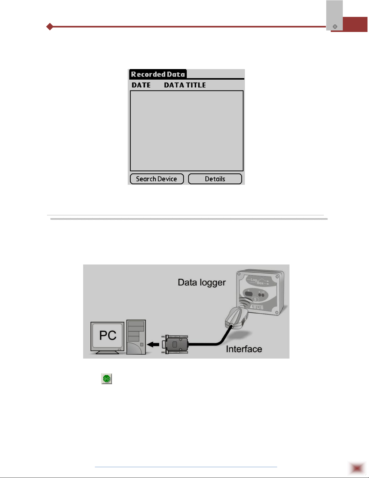
Starting the LogChart PalmOS application will display the Recorded Data screen on the Palm
from where it is possible to access the logger to change settings and collect data, as well as to access
collected data.
Recorded Data screen
Log Box-AA
6. CONFIGURATION
Make sure the IR-LINK3 wand is connected to the PC. The interface must be
pointed towards the logger communication window (see Figure below) at a distance of
about 15 cm.
Infrared interface position
Click the button to start the communication between the logger and the
software; the Parameters Configuration window is then displayed (as shown in figure
Configuration Window, below), showing the current configuration and information
about the logger.
ABUS TECHNOLOGIES INC.
12
Page 13

New configuration parameters defining the operation mode for a new
application can be entered. The user can also obtain general information about the
device. The fields of the configuration window are described below:
Log Box-AA
Configuration window
6.1 General Information Field
General information on the top of the screen informs the model, serial number, logger current
date/time, PC date/time, firmware version (logger model version), memory capacity and used memory.
This information is displayed in the upper part of the LogChart-II configuration screen. The time is
constantly updated in this screen, provided that the logger and the PC are communicating.
6.2 Acquisitions Field
Interval: It determines the interval between readings in the hh:mm:ss format.
New data is stored in the logger memory after each time interval. In the
Instantaneous reading mode, the value of the interval between
acquisitions is the same as the time interval between measurements.
For Average, Minimum and Maximum readings, the logger executes
10 readings within this interval.
External Battery Switch time: Defines the time when the logger turns on the power supply, before
proceeding with any reading. This time is limited to 10 seconds and
must be less than half of the interval between readings.
Estimated time: It informs the estimated time for the accomplishment of programmed
readings based on the logging “Interval” and on the number of
programmed readings.
Daily Repetition: Allows loggings to be repeated everyday, for example, recording data
from 8 AM to 5 PM day after day. The start and stop times are defined
in the fields “Start time” and “Stop time.”
ABUS TECHNOLOGIES INC.
13
Page 14

6.3 Start Loggings Field
Immediately: The logger starts logging as soon as the configuration is applied. Not
valid when the option ‘Daily Repetition’ is selected.
Start via Palm: Logging is started via Palm. The LogPalm software must be installed in
the PDA. (See Palm User under this section)
Day / Hour: Logging starts at a defined date and time. The date defined is used for
the Daily Repetitions option as well. Through Start Button Starts and
stops logging by pressing the Star button for two seconds.
Digital Input: Starts readings when the digital input is activated (closed) and stops
readings when the digital input is deactivated (open).
6.4 Stop Loggings Field
At Full Memory: Loggings can be stored up to the full memory capacity is reached.
Wrap around: Logging never stops. The LogBox-AA will keep on recording the
readings and when the memory is full it will overwrite the oldest record
in a circular or wrap around manner.
After a defined number of readings: The logger will stop logging after the number of readings here
defined is reached. Not valid when the option ‘Daily Repetition’ is
selected.
Day / Hour: The LogBox-AA will stop logging at the user-defined date and time. Not
valid when the option ‘Daily Repetition’ is selected.
6.5 Channels Field
By selecting the “Channels” option, the user is able to choose the individual settings for each
input channel, as Figure below shows.
Log Box-AA
Parameters for Input Channels Configuration
ABUS TECHNOLOGIES INC.
14
Page 15

Such parameters are:
Tag: Defines a name (up to 8 characters) for identifying the variable to be
measured.
Inputs: The signal applied to the logger second input is defined here. The list
shows all the input options available. The selected option must be in
accordance with the internal configuration of the jumper, as Table 01
shows.
Unit: Defines the variable unit.
Scale: Defines the range, in engineering units, for representing the input
variable measured. Adjustable from –32000 to +32000 for 4-20 mA, 020 mA, 0-50 mV and 0-10 inputs, for the remaining input times the
scale is fixed.
Offset: Allows fine offset corrections on the measured value.
Value: Defines readings recording mode:
Instantaneous: The instant value read at the logging time.
Average: Ten readings at each reading interval. The average value of
readings is the value recorded;
Minimum: Ten readings at each reading interval. The lowest value
found is recorded;
Maximum: Ten readings at each reading interval. The highest value
found is recorded;
Alarm: It defines a limit range of variables measured that, once exceeded,
trigger the alarm. Once activated, the alarm LED indicator stays so
even after the alarm-triggering situation has ceased. LOW defines the
minimum value under which the alarm is triggered; HIGH defines the
maximum value above which the alarm sensor is triggered.
After filling all the fields, send the configuration to the logger by clicking on the button
Log Box-AA
New settings and PC current date/time are then sent to the logger.
6.6 Palmtop User
To set up the communication between the handheld device and the logger(s), run LogChart
Palm-OS, press the Search Device button from the Recorded Data screen and align the Infrared Port
of the PDA to the logger(s) communication window. If more than one loggers are detected, the Devices
Found screen is exhibited.
Devices Found screen
ABUS TECHNOLOGIES INC.
15
Page 16

The user must select a device to start the communication. The Monitoring screen is soon
displayed. If your Palm detects only one device, the Devices Found screen is skipped and the
Monitoring screen is exhibited.
Monitoring screen
Log Box-AA
The screen exhibits instant values of variables measured, configuration information and current
logger status. Buttons are assigned the following functions:
Search: It allows you to "search" for another logger or reconnect communication lost for
any reason. When the handheld device finds a logger, it exhibits a new
Monitoring screen with the logger information. When other loggers are found,
the Devices Found screen is exhibited again.
Download: Downloads logged data. Download can be partial and it does not interfere in the
ongoing acquisition process.
More Info: Displays further information on the connected logger, such as model, serial
number, memory capacity and version.
Settings: Accesses the Settings screen, which allows modifying the logger configuration.
Data Base: Exhibits the Recorded Data screen listing all the processes stored and
processed in the PDA data base. To access the data, tap on Details.
Information required is displayed. View Data: displays data in a list containing
date, time and measured value.
Recorded Data screen
ABUS TECHNOLOGIES INC.
16
Page 17
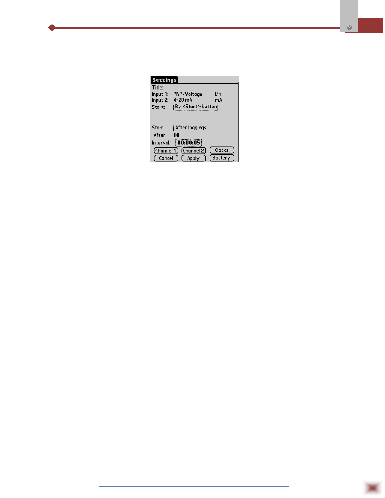
During configuration, the logger and the Palm ports must be aligned. Tap on Settings in the
Monitoring screen. The screen Settings is opened and contains the required parameters for
configuring the logger.
Settings screen
The parameters are analogous to the LogChart II parameters. They are:
Log Box-AA
Title: Name of the process.
Input 1 and 2: Informs the inputs used by channels 1 and 2 respectively.
Start: Defines the strategy for the logging start. Options are:
Immediately: The logger starts logging as soon as configuration is sent to
the logger.
By date/time: Start in defined data and time, always after current time. It is
possible to perform daily repetitions. If this option is selected, a new box to
define the stop logging time is displayed.
By <Start> Button: Press the Start_Now button from the Monitoring screen
to start logging.
By LogBox Button: Press the Start_Now button from the Monitoring screen,
the Palmtop should be pointed towards the logger.
By Digital Input: Readings are performed while the digital input is enabled
(closed / 1) and interrupted when the digital input is disabled (open / 0).
Stop: Defines logging stop mode: Options are:
Full memory: Loggings can be stored up to the logger full memory capacity
is reached.
Wrap around: Logging never stops. The LogBox will keep on recording the
readings and when the memory is full it will overwrite the oldest record in a
circular or wrap around manner.
After loggings: The logging will stop after the number of readings here
defined.
By date/time: Logging is stopped on user-defined day and time.
Interval: Defines the interval between readings: hour, minute and second. For mean,
maximum and minimum values, the shortest interval between loggings is 10
seconds.
ABUS TECHNOLOGIES INC.
17
Page 18

Channel 1: Opens the Input 1 Settings screen.
Tag: Defines a name for Channel 1.
Input: Informs the input type used in Channel 1:
Unit: Defines the unit of the variable. For 0-20mA, 4-20mA, 0-50mV and 0-10V
the user should write the required unit.
Logging Mode: It defines how the value measured will be logged. Options are:
Instantaneous: One reading and one logging at each reading “Interval”;
Average: Ten readings at each reading interval. The average value of readings
is the value recorded;
Minimum: Ten readings at each reading interval. The lowest value found is
recorded;
Maximum: Ten readings at each reading interval. The highest value found is
recorded;
Lower/Upper Range Value: Allows the user to define the reading range for the
Log Box-AA
0-20mA, 4-20mA, 0-50mV and 0-10V inputs.
Offset: This parameter is used to correct small known mistakes the input signal
may present, such as during sensor switching, transmitter replacement, etc.
Alarms: Enables an alarm that is triggered according to user-defined
parameters.
Alarm settings screen
Cancel and OK buttons cancel and save configurations defined in Channel 2 screen.
Channel 2: Has the same parameters as described for Channel 1.
Clocks: Provides access to Logger and Palm clocks. When a new configuration is sent
to the logger, clocks are updated.
Battery: Defines the moment when the logger turns on the battery switch, before each
reading is performed. Time (up to 10 seconds) can not exceed the mean time
between measurements.
After configuring clocks, click Apply to send this configuration to the Logger, returning to the
Monitoring screen.
ABUS TECHNOLOGIES INC.
18
Page 19
7. OPERATION
The logger operation mode is user-defined in the LogChart-II software. To
access or change this configuration, the IR-LINK3 interface is required. The user must
install the LogChart-II software in a computer and run the logger configuration
according to instructions defined in the LogChart-II installation section of this manual.
After configuration and input electric connections are made, the device is ready
to measure and log input signals. The status indicator shows the logger current status.
7.1 Offloading Data
The transference of data to a PC is accomplished by using the LogChart II software. Data can
be collected anytime and saved in files for future analysis (menu “File Save” or “File Save as”). Help can
be accessed from the LogChart-II software when necessary. Offloading data: data offload is
Log Box-AA
accomplished by clicking on the button , or using the LogChart-II menu. During data transference, a
status bar indicates remaining data to be transferred. Data offloading time is proportional to the number
of readings logged. At the end of data transference, the Graph window is displayed as shown blow.
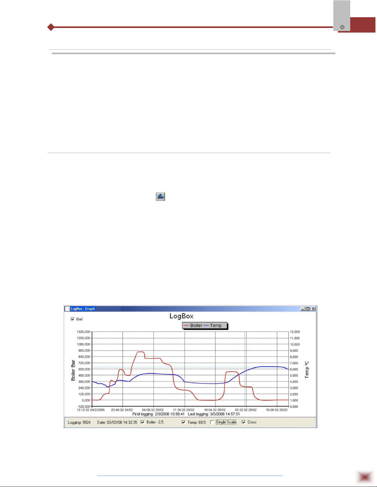
7.1.1 Graph window
The Graph is a convenient tool for analysis. It enables the logger acquisitions to be read in the
form of a “values x time” graph. As one moves the mouse in the chart area, the time and the value of
the records of each channel are shown in the field located in the bottom of the window.
Zooming in and out are implemented. It is possible to select an area by clicking and dragging
the mouse, thus creating a zoom region, starting at the upper left position of the region of interest.
Graph window.
NOTE: The command Offload acquisitions does not interrupt the process of data logging and reading.
Other two windows can be easily opened: General information window and Tables window.
ABUS TECHNOLOGIES INC.
19
Page 20
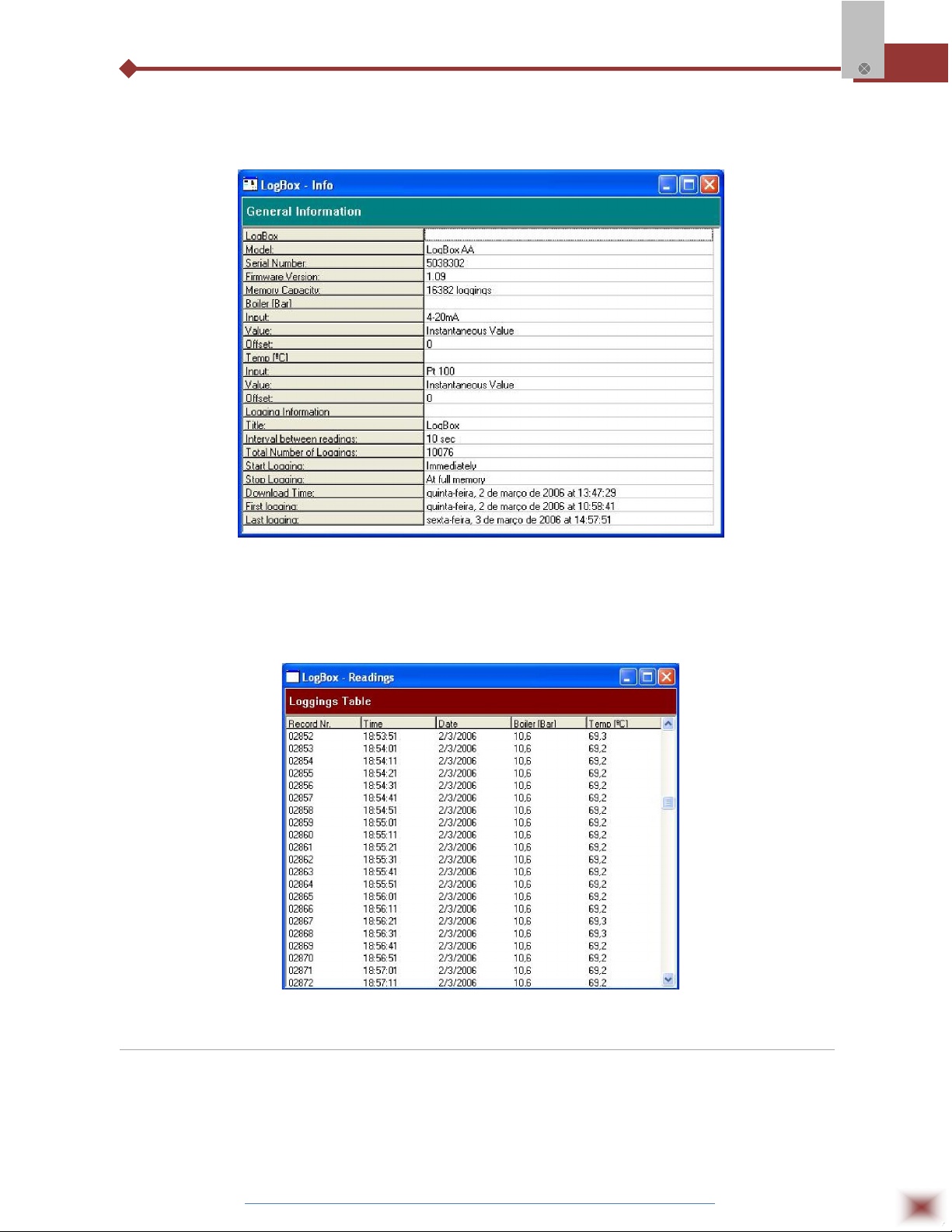
7.1.2 General information table
Displays information about the logger that registered data: its features and configurations, and
details about data acquired.
Log Box-AA
General Information window
7.1.3 Acquisitions Table Window
Data acquired by one or both input channels (user-defined) are displayed in engineering units in
a table format. The table displays register number, date/time and the record values.
Screenshot showing the acquisitions table
7.2 Visualization Data
Three windows support data visualization: Graph, Acquisitions Table and General Information
windows. Data can be originated from direct reading from the logger or from a file previously recorded in
a computer. Once the windows are open, data can be saved in a file (.lch), printed on a graph or
exported to a text file (.txt or .dat).
ABUS TECHNOLOGIES INC.
20
Page 21
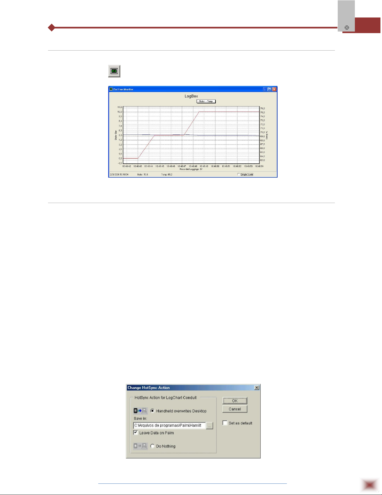
7.3 Monitoring Acquisitions
To visualize current measurements in a graph format, use the Monitor On-Line command by
clicking on the button , while pointing the IR-LINK3 interface to the logger.
Log Box-AA
Online monitoring graph
7.4 Palmtop User
7.4.1 DOWNLOADING DATA FROM THE LOGGER
In the Monitoring screen, the Download button performs the transfer of the data from the Log
Box to the PDA. Download can be partial and it does not interfere in the ongoing acquisition process.
The data base of loggings is displayed in the Recording Data screen, identified with the name assigned
to the process (Title) and the date it was downloaded. Should the PDA batteries be discharged, all
readings will be lost.
7.4.2 FILES VISUALIZATION
The Recorded Data screen lists the data base logged and stored in the PDA. To access data,
select the desired data base and tap on Details. Recorded Data Details screen shows information
about the data base. View Data shows in table format the logged values and the date and time they
were performed. Press Delete to erase the selected data base.
7.4.3 TRANSFERRING DATA TO YOUR DESKTOP
HotSync of data stored in a PDA to a PC is performed through a conduit installed together with
the LogChart Palm-OS. The conduit converts the data collected by the LogChart Palm-OS to a file
compatible with the LogChart-II software.
To access the conduit options, the HotSync Manager software must be active. Click with the
right mouse button on the HotSync Manager in the Windows Taskbar. Select in the drop-down menu
the option Custom. Select ABUS LogChart Conduit and click Change. The following window will be
exhibited:
LogChart Conduit options
ABUS TECHNOLOGIES INC.
21
Page 22

Handheld overwrites Desktop: LogChart Palm-OS files are transferred to the Desktop.
Save in: Choose a directory to record files generated during data
synchronization.
Leave Data on Palm: Option to keep or delete the data in the PDA after HotSync.
Do nothing: Data synchronization will not be performed;
Set as default: The same settings will be used in the next HotSync processes.
8. MAINTENANCE
8.1 Observation
1. The logger is an electronic device and some basic care is required:
2. When opening the device for battery replacement or connecting sensors avoid touching the circuit
Log Box-AA
for not causing damages resulting from static electricity.
3. When the device is opened, avoid liquid and/or dust contact.
4. Use a screwdriver to open the case cover.
5. Pay attention to batteries polarity: The positive terminal should be placed directed towards the
center of the device.
6. Worn batteries should not be recharged, dismantled or incinerated. After use, batteries must be
disposed according to local legal rules or returned to ABUS.
7. After placing batteries back to the logger, make sure the cover is firmly attached to the socket.
8.2 Troubleshooting
FAULT POSSIBLE CAUSE RESOLUTION
LED is not
Flashing
No
Communication
1. The LED flashing light is
intentionally weak, and it can be
difficult to see it in illuminated
environments.
2. Make sure it is not flashing at all.
Communication with the logger fails
1. Make sure the battery is installed
correctly;
2. Make sure the battery is not
discharged;
1. Make sure the COMM port is
selected correctly and there is no
other program using the same port
during communication attempts;
2. Make sure there is no physical
obstacle blocking the infrared
signal;
3. Make sure the cable is well
connected to the PC port;
4. Make sure the port selected does
not present any problem;
ABUS TECHNOLOGIES INC.
22
Page 23

9. SAFETY PRECAUTIONS
1. The unit should be powered for 15 minutes before use.
2. Use in ambient temperature of 0-60˚C.
3. Avoid vibrations, shock, excessive dust, corrosive chemical materials or gaseous
environment.
4. Input wire should not be too long. If measured signal have to be far away from the
unit, please use 2-core shielded cable.
5. Use this instrument in the scope of its specifications, otherwise fire or malfunctions
may result.
6. Contact of the instrument, with organic solvents or oils should be avoided.
Log Box-AA
7. Do not turn on the power supply until all of the wiring is completed. Otherwise
electrical shock, fire or malfunction may result.
8. Do not disassemble, repair or modify the instrument.
9. All connections should be tightened properly.
10. Power supply should be constant, should not be fluctuating.
10. WARRANTY
ABUS provides the original purchaser of this instrument a one (1) year warranty
against defects in material and workmanship under the following terms:
The one year warranty begins on the day of shipment as stated on the sales bill.
During the warranty period all costs of material and labor will be free of charge
provided that the instrument does not show any evidence of misuse.
For maintenance, return the instrument with a copy of the sales bill to our factory.
All transportation and insurance costs should be covered by the owner of the
equipment.
Should any sign of electrical or mechanical shock, abuse, bad handling or misuse
be evident the warranty voids and maintenance costs will be charged.
ABUS TECHNOLOGIES INC.
www.abustek.com, E-M ail: info@abustek.com
ABUS TECHNOLOGIES INC.
23
 Loading...