


ITAC10120
ITAC10130
D Bedienungsanleitung
User manual
Originalbedienungsanleitung in deutscher Sprache. Für künftige Verwendung aufbewahren.
This user manual contains important information for installation and operation.
This should be also noted when this product is passed on to a third party.
Therefore look after these operating instructions for future reference!
Version 05/2019
D
Merkmale:
• Anschlüsse:
ITAC10120: 16 x PoE Gigabit (Downstream), 4 x Gigabit (Uplink) SFP
ITAC10130: 24 x PoE Gigabit (Downstream), 4 x Gigabit (Uplink) SFP
• Unterstützt PoE and PoE+
• Temperaturgesteuerter Lüfter
• Unterstützt webbasiertes Layer 2 Netzwerkmanagement und simples PoE-
Management
• Unterstützt High-Speed Data-Forwarding, besonders geeignet für große
Datenmengen bei professioneller Videoüberwachung
• Geeignet für professionelle Installation im 19" Rack
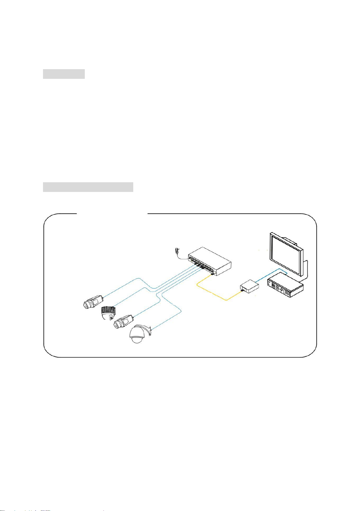
Installationsübersicht:
Achtung:
Die Übertragungsdistanz hängt von der Signalquelle und der Kabelqualität ab.
Es wird dringend empfohlen, ein Standard Cat5e / 6 Ethernet-Kabel zu verwenden,
um die maximale Übertragungsdistanz zu erreichen.
Switch
NVR
CAT Kabel
PoE
Kameras

Zugriff auf Web Management via Downlink Port
Um sich auf die Web Management Oberfläche zu verbinden, schließen Sie ein
Netzwerkkabel an einem der 1-16/1-24 Downlink Ports an und geben im Browser
folgende Daten ein.
Die Werkseinstellungen lauten:
IP-Adresse: 192.168.1.200
Benutzer: admin
Passwort: admin
Zugriff auf Web Management via CLS Port
Um sich auf die Web Management Oberfläche zu verbinden, schließen Sie ein
Konsolenkabel (RJ45 -> R232 serial port 115200,8,N,1) am CLS Port, am PC am
seriellen Port (DB9) an und geben Browser folgende Daten ein.
Die Werkseinstellungen lauten:
IP-Adresse: 192.168.1.200
Benutzer: admin
Passwort: admin
Reset
Neustart: Drücken Sie kurz die Reset-Taste um den Switch neu zu starten.
Rücksetzten auf Werkseinstellungen: Drücken Sie die Reset-Taste für mehr als 10
Sekunden, um den Switch auf Werkseinstellungen zurück zu setzen.
OOB Downlink Gigabit PoE Ports Status Power
Console LED LED
Reset Uplink Gigabit SFP Ports
Erdung AC100~240V
Spannungseingang

Technische Daten:
Artikelnummer
ITAC101020
ITAC10130
Abmessungen (LxBxH)
442 x 320 x 45 mm
Leistungsaufnahme
320 W
450 W
Max. Betriebstemperatur
50 °C
Max. Luftfeuchtigkeit
95 %
Max. PoE Leistung pro Port
30 Watt
Min. Betriebstemperatur
-10 °C
Nettogewicht
4,35 kg
Netzwerk Standards
IEEE802.3 , IEEE802.3u,
IEEE802.3ab, IEEE802.3Z,
IEEE802.3X,
IEEE 802.1Q, IEEE
802.1p, IEEE 802.3ad,
IEEE 802.1D, IEEE
802.1X
Netzwerkanschluss
Downstream: 16x
10/100/1000Base-T
PoE RJ45(Auto-MDI/
MDI-X), Uplink: 4*1000
Base-X SFP(Mini-
GBIC), Konsole: 1x
RJ45-R232 serial port(
115200,8,N,1), OOB:
1x 10/100Base-TX RJ45
(Web Management)
Downstream: 24x
10/100/1000Base-T
PoE RJ45(Auto-MDI/
MDI-X), Uplink: 4x
1000 Base-X SFP(Mini-
GBIC), Konsole: 1x
RJ45-R232 serial port(
115200,8,N,1), OOB:
1x 10/100Base-TX RJ45
(Web Management)
Pin Zuordnung Stromversorgung
1/2(+), 3/6(-)
PoE Leistung gesamt
270 Watt
390 Watt
PoE Standard
802.3af/at (PSE)
Spannungsversorgung AC
100~240 V

Features:
• Connections:
ITAC10120: 16 x PoE gigabit (downstream), 4 x gigabit (uplink) SFP
ITAC10130: 24 x PoE gigabit (downstream), 4 x gigabit (uplink) SFP
• Supports PoE and PoE+
• Temperature-controlled fan
• Supports web-based Layer 2 network management and simple PoE
management
• Supports high-speed data-forwarding, particularly suitable for large volumes of
data in professional video surveillance
• Suitable for professional installation in a 19” rack
Installation overview
Attention:
The transmission distance depends on the signal source and the cable quality.
It is strongly recommended to use a standard Cat5e / 6 Ethernet cable to achieve the
maximum transmission distance.
PoE
Cameras
Switch
NVR
CAT Cable

Access to Web Management via Downlink Port
To connect to the web management interface, connect a network cable to any of 116/1-24 Downlink port and enter the following data into browser.
The default factory settings are:
IP-Address: 192.168.1.200
User: admin
Password: admin
Access to Web Management via CLS Port
To connect to the web management interface, connect a console cable (RJ45 ->
R232 serial port 115200,8, N, 1) to the CLS port, to the PC at the serial port (DB9)
and enter the following data into the browser.
The default factory settings are:
IP-Address: 192.168.1.200
User: admin
Password: admin
Reset
Restart: Press the reset button to restart the switch.
Reset to default factory settings: Press the reset button for more than 10 seconds to
reset the switch to default factory settings.
OOB Downlink Gigabit PoE Ports Status Power
Console LED LED
Reset Uplink Gigabit SFP Ports
Grounding AC100~240V
Power Input

Specification:
Item #
ITAC10120
ITAC10130
AC voltage supply
100~240 V
Dimensions
442 x 320 x 45 mm
Max. PoE power per port
30 Watt
Max. operating temperature
50 °C
Max. humidity
95 %
Min. operating temperature
-10 °C
Net weight
4,35 kg
Network standards
IEEE802.3, IEEE802.3u,
IEEE802.3ab, IEEE802.3Z,
IEEE802.3X,
IEEE 802.1Q, IEEE802.1p, IEEE 802.3ad,
IEEE 802.1D, IEEE802.1X
Network ports
Downstream: 16x
10/100/1000Base-T
PoE RJ45(Auto-MDI/
MDI-X), Uplink: 4*1000
Base-X SFP(Mini-
GBIC), Konsole: 1x
RJ45-R232 serial port(
115200,8,N,1), OOB:
1x 10/100Base-TX RJ45
(Web Management)
Downstream: 24x
10/100/1000Base-T
PoE RJ45(Auto-MDI/
MDI-X), Uplink: 4x
1000 Base-X SFP(Mini-
GBIC), Konsole: 1x
RJ45-R232 serial port(
115200,8,N,1), OOB:
1x 10/100Base-TX RJ45
(Web Management)
PoE Standard
802.3af/at (PSE)
Power Pin Assignment
1/2(+), 3/6(-)
Power consumption
320 W
450 W
Total PoE power
270 W
390 W

D Impressum
Diese Bedienungsanleitung ist eine Publikation der ABUS Security-Center GmbH & Co. KG,
Linker Kreuthweg 5, 86444 Affing. Alle Rechte einschließlich Übersetzung vorbehalten.
Reproduktionen jeder Art, z.B. Fotokopie, Mikroverfilmung, oder die Erfassung in
elektronischen Datenverarbeitungsanlagen, bedürfen der schriftlichen Genehmigung des
Herausgebers.
Nachdruck, auch auszugsweise, verboten.
Diese Bedienungsanleitung entspricht dem technischen Stand bei Drucklegung.
Änderung in Technik und Ausstattung vorbehalten.
Imprint
These operating instructions are published by ABUS Security-Center GmbH & Co.KG, Linker
Kreuthweg 5, 86444 Affing, Germany. No reproduction (including translation) is permitted in
whole or part e.g. photocopy, microfilming or storage in electronic data processing equipment,
without the express written consent of the publisher.
The operating instructions reflect the current technical specifications at the time of print.
We reserve the right to change the technical or physical specifications.
© Copyright 05/2019 by ABUS Security-Center
 Loading...