

Page 1
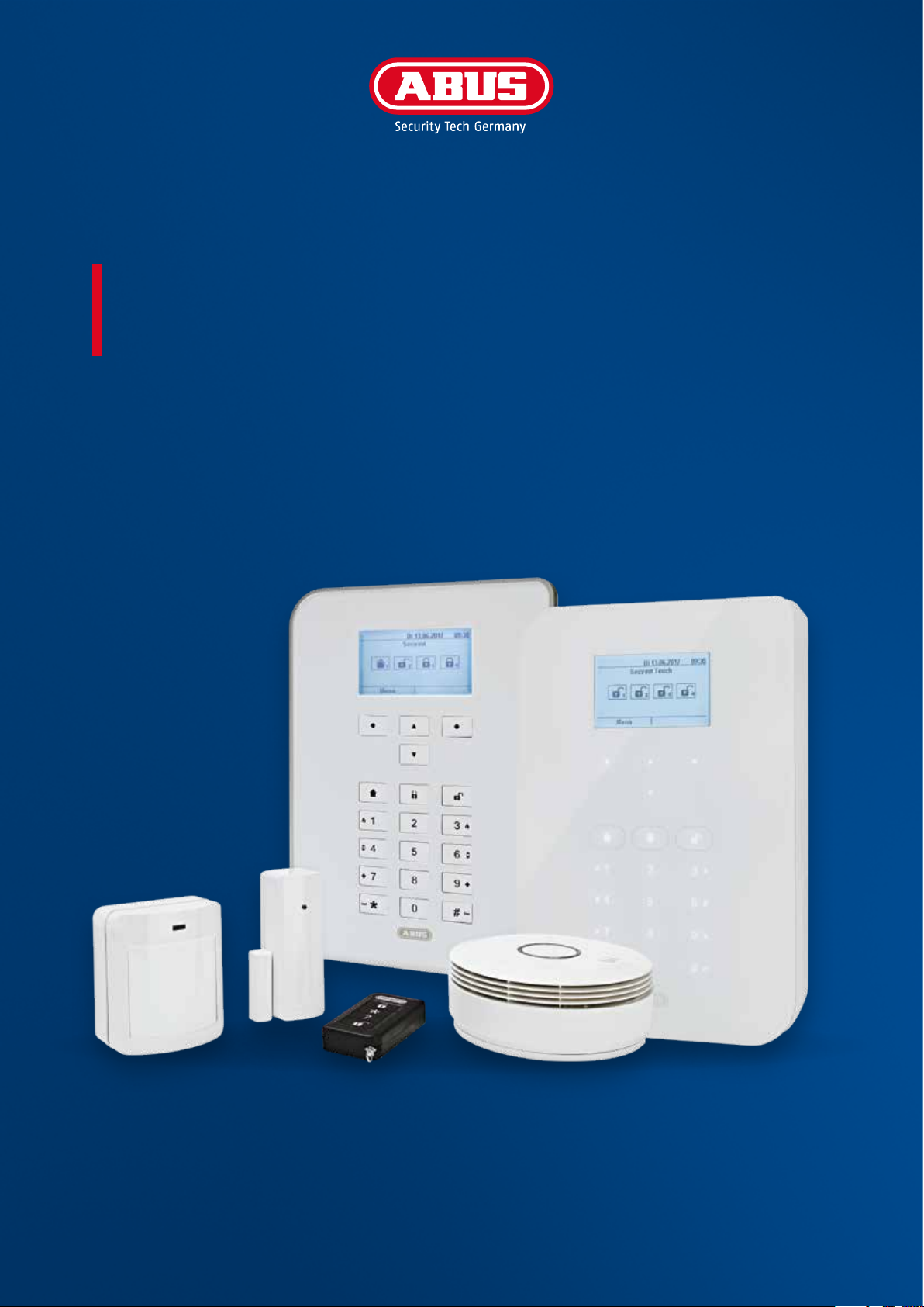
SECVEST
USER GUIDE
V3.01.11
abus.com
Page 2

CONTENTS
English
1. Scope of delivery .................................................................................................. 4
2. General ............................................................................................................. 5
2.1 Safety information ........................................................................................... 5
2.2 Information on user guide ................................................................................ 6
2.3 Warranty ....................................................................................................... 6
2.4 Disposal ........................................................................................................ 6
2.5 Declaration of conformity .................................................................................. 6
3. Installation example ............................................................................................. 8
4. Overview of the system and control panel ................................................................. 9
5. Overview of the numerical keypad ........................................................................... 10
6. Secvest display .................................................................................................... 12
7. Menu navigation and operation .............................................................................. 13
8. Arming and disarming the system ........................................................................... 13
8.1 Arming/disarming keys ..................................................................................... 13
8.2 Graphical display of arming/disarming on the display ............................................. 14
8.3 Arming/disarming via the quick arm keys ............................................................. 14
8.4 Arming via the user code .................................................................................. 14
8.5 Arming sub-areas ........................................................................................... 16
8.6 Individual sub-areas ....................................................................................... 17
8.7 Internal arming .............................................................................................. 17
8.8 Internal arming via chip key ............................................................................. 18
8.9 Internal arming via remote control ..................................................................... 18
8.10 Arming via wireless control panel ...................................................................... 18
8.11 Arming via remote control ................................................................................ 18
8.12 Arming via chip key ........................................................................................ 19
8.13 Arming via delay times .................................................................................... 19
8.14 Preventing arming of the system ....................................................................... 20
9. Responding to an alarm ........................................................................................ 21
9.1 Alarm types .................................................................................................... 21
9.2 Alarm forwarding ............................................................................................ 22
9.2.1 Alarm forwarding via telephone .................................................................. 22
9.2.2 Alarm forwarding to a monitoring station ..................................................... 23
9.2.3 Alarm forwarding via email ........................................................................ 23
9.2.4 Alarm forwarding via text message .............................................................. 23
9.2.5 Alarm forwarding in the event of a personal or medical emergency .................... 23
10. User menu ........................................................................................................ 24
10.1 Users .......................................................................................................... 26
10.2 Voice memo ................................................................................................ 27
10.3 Hide zones .................................................................................................. 27
10.5 System conguration ..................................................................................... 28
10.5.1 Functions .............................................................................................. 28
Contents
Page 3

10.5.2 Date & time .......................................................................................... 33
10.5.3 Edit outputs .......................................................................................... 34
10.5.4 Remote controls ..................................................................................... 35
10.5.5 Volume settings .................................................................................... 35
10.5.6 Web access ........................................................................................... 35
10.5.7 Remote updates ..................................................................................... 36
10.5.8 Time schedules active/inactive .................................................................. 36
10.6 Contacts ..................................................................................................... 36
10.7 Test............................................................................................................ 38
10.7.1 Walk test ............................................................................................... 38
10.7.2 Sirens & sounders ................................................................................... 39
10.7.3 Door locks ............................................................................................. 39
10.7.4 Outputs ................................................................................................ 39
10.7.5 Chip key ............................................................................................... 39
10.7.6 Remote controls ..................................................................................... 40
10.7.7 Emergency buttons .................................................................................. 40
10.7.8 Telephone call ....................................................................................... 40
10.8 Log ........................................................................................................... 40
10.9 Information ................................................................................................ 41
10.9.1 Alarm panel .......................................................................................... 41
10.9.2 Communication ..................................................................................... 42
11. Advanced system operation ................................................................................... 44
11.1 Remote control .............................................................................................. 44
11.2 Wireless cylinder lock (“Secvest key”) ................................................................. 44
11.3 Additional door lock (FU7010/7025E) ................................................................... 44
11.4 Operation via telephone .................................................................................. 45
12. Operation via web (app/browser) ............................................................................ 46
12.1 Operation via web browser .............................................................................. 46
12.2 Operation via app.......................................................................................... 46
13. Operation via web browser.................................................................................... 47
13.1 Setting the Secvest IP address ........................................................................... 48
13.2 Overview of the web interface .......................................................................... 48
13.3 Arming & disarming ....................................................................................... 49
13.3.1 Hide zones ........................................................................................... 50
13.4 Additional web interface options ...................................................................... 51
13.5 Conguring Secvest “time schedules” ................................................................ 54
13.6 Datasets ...................................................................................................... 57
13.7 Exceptions ................................................................................................... 57
14. Terms and denitions .......................................................................................... 60
15. Technical data .................................................................................................... 67
16. Troubleshooting ................................................................................................. 80
3|22
Page 4

Dear Customer,
Thank you for purchasing this SECVEST wireless alarm panel. This device is built with state-of-the-art
technology and it complies with current domestic and European regulations. Conformity has been
proven, and all related certications are available from the manufacturer on request (www.abus.com).
To guarantee safe operation, it is essential that you observe the instructions in this user guide.
If you have any questions, please contact your specialist dealer.
Everything possible has been done to ensure that the content of these instructions is correct. However,
neither the author nor ABUS Security-Center GmbH & Co. KG can be held liable for loss or damage caused
by incorrect or improper installation and operation or failure to observe the safety instructions and
warnings. No liability can be accepted for resulting damage. No part of the product may be changed
or modied in any way. If you do not follow these instructions, your warranty claim becomes invalid.
Subject to technical modications.
© ABUS Security-Center GmbH & Co. KG, 11/2018.
We reserve the right to make changes to this manual without prior notice. This wireless alarm panel
is suitable for use in combination with detectors and sounders for the protection of property, such as
your company, home, garage, garden shed and holiday home.
1. SCOPE OF DELIVERY
The following components are included in the scope of delivery for your new Secvest product:
• Wireless alarm panel
• Rechargeable battery
• Quickstart guide
• Mounting material
3 x screws
Battery
Quickstart
guide
3 x screw anchors
1
2
4
5
7
8
0
*
#
3x 3x
3
6
9
1. Scope of delivery
Page 5

2. GENERAL
2.1 Safety information
The alarm panel and its connected components must not under any circumstances come into contact with
water, such as in the bathroom. Using the device for purposes other than those described may damage
this product and may also lead to hazards such as short circuits, re or electric shock. The power supply
unit is suitable for operation on the public electrical grid with 230VAC/50Hz. No part of the product may
be changed or modied in any way. Connection to the public electrical grid is subject to your country’s
specic regulations. Please seek information on these regulations before connecting the product to the
public grid. Only use the device for the purpose for which it was built and designed. Any other use is
considered unintended.
During the initial set-up of the alarm control panel there is neither a predefined standard installer code
nor a predefined standard administrator code. These need to be individually assigned in the set-up
wizard.
Aer the initial start-up please change the default installer name (code = name) as well as the default
administrator name (code = name) to secure user names. When adding users, please make sure you
are careful about how log-in details are handled.
Handling log-in details for your security systems
Basics:
• User names and codes for logging into security systems should be known only
by the legal owners and never given out to unauthorised parties.
• If you have to pass this information on via email, please take care to send the
user name and code in two separate emails.
• User names and codes should be changed regularly.
Standards:
• User names must be at least eight characters long.
• They should ideally contain characters from at least three of the following categories:
uppercase letters, lowercase letters, special characters, and numbers.
• User names should never contain your own name, the name of a family member, your pet,
your best friend or your favourite celebrity, or your hobby or date of birth.
• Avoid using user names and codes that you use on other websites or that could be
easily guessed by others.
• Your user name should not be able to be found in a dictionary and should never be a product name.
• It should not be a conventional series of characters, a repeated pattern or a keyboard pattern,
such as asdfgh or 1234abcd.
• You should avoid only using numbers at the end of your user name or using one of the more typical
special characters (!). ? #) at the beginning or end to compensate for an otherwise simple user name.
• User names and codes should be changed at least every 180days.
• New user names and codes should not be identical to any of the three combinations used before them.
• New user names and codes should dier from user names and codes that have been used before
by at least two characters.
• Macros and scripts should not be used to input user names and codes.
2. General
5|44
Page 6

2.2 Information on user guide
These instructions contain important installation and operation information. Follow the directions and
instructions in this user manual to ensure safe operation. Store this manual in a safe place for future
reference. This manual constitutes part of the device. If you pass the device on to third parties, please
remember to include this manual.
Note
S/W 3.01.11
This manual relates to soware version 3.01.11 and all other previously published soware versions.
All new features that are only valid from a certain soware version are marked accordingly, e.g.
>=2.00.00. All other features that are valid up to a certain soware version are also marked
accordingly, e.g. <2.00.00.
2.3 Warranty
In the event of a warranty claim, the original receipt with the date of purchase and a short written
description of the problem must be supplied with the product. If you discover a defect on your wireless
alarm panel which existed at the time of purchase, contact your dealer directly within the rst two years.
2.4 Disposal
Dispose of the device in accordance with EU Directive 2002/96/EC – WEEE (Waste Electrical and Electronic
Equipment). If you have any questions, please contact the municipal authority responsible for disposal.
You can get information on collection points for waste equipment from your local authority, from local
waste disposal companies or your dealer, for example.
2.5 Declaration of conformity
ABUS Security-Center hereby declares that the radio equipment type FUAA50xxx is in compliance with
RED Directive 2014/53/EU. The full EU Declaration of Conformity text can be found at: www.abus.com
Artikelsuche FUAA50xxxx/Downloads
The Declaration of Conformity can also be obtained from the following address:
ABUS Security-Center GmbH & Co. KG, Linker Kreuthweg 5, 86444 Ang, GERMANY
Safety information
Page 7

7|6
Page 8
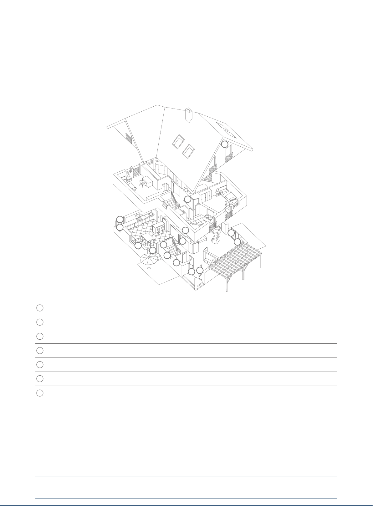
3. INSTALLATION EXAMPLE
The following provides a simple installation example to show some important basic applications for the
alarm system. The example focuses on a single-family detached home. A representative installation has
been illustrated here, as an example of how it could be implemented in a similar or more advanced
form for your property as well:
5
7
1
1
1
4
1
7
3
1
1
1
2
1
4
The following components are installed in this example:
1
8 x magnetic contacts at the windows and doors
2
1 x Secvest key (wireless cylinder lock) at the doors for easy arming/disarming
3
1 x Secvest alarm panel
4
2 x motion detectors indoors
5
1 x wireless outdoor siren under the roof
6
1 x wireless control panel in the bedroom
7
1 x info module in the hallway
Perimeter protection: Protects against all possibility of access from outside (windows, doors, etc.).
An alarm is triggered as soon as someone gains access to the property.
Interior protection: Predominantly used as a second line of defence, armed when the occupants
of the building are away so that the perimeter protection acts as the rst
alarm and the interior protection as additional security against intruders.
Internal arming: If you are in the building you can arm just the detectors for the perimeter
protection. The motion detectors indoors remain disabled in this case.
External arming: All available detectors on the premises are enabled.
An overview of all important terms concerning the alarm panel and alarm system can be found
in the appendix under "Terms and denitions".
3. Installation example
Page 9
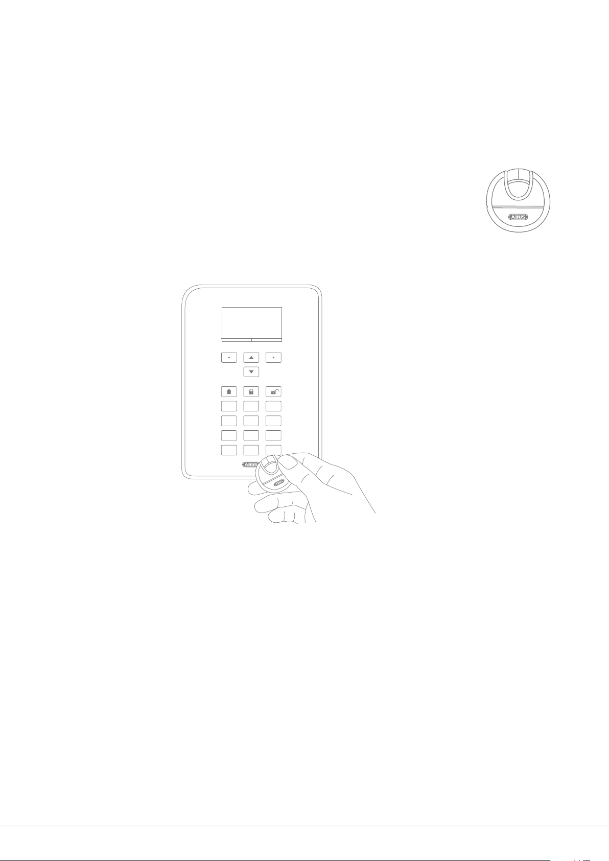
4. OVERVIEW OF THE SYSTEM AND CONTROL PANEL
1
4
2
8
7
1
4
6
7
*
5
Graphical display for status, menus and additional information
1
Keys for menu navigation (see "Menu navigation")
2
Quick disarm key for disarming the complete system (code entry required)
3
Microphone opening
4
Proximity chip key reader area
5
2
5
8
0
3
6
9
#
3
Numerical keypad (see following page)
6
"Internal arm" key for quick arming of perimeter protection
7
8
Quick arm key for arming the complete system
4. Overview of the system and control panel
9|88
Page 10

5. OVERVIEW OF THE NUMERICAL KEYPAD
The numerical keypad is used to enter values in certain menus. Letters and special characters
are also stored on the keypad for entering things like user names or email addresses.
The numerical keypad can be used to input various information.
For example, a name can be entered when creating a new user
(see "Users"). The letters are not printed on the numerical keypad
1
2
3
in order to provide a better overview during day-to-day operation.
Letters are entered according to the legend provided below.
4
7
*
5
8
0
6
9
#
In addition to data input, numerical keys 1/3, 4/6, 7/9 and the */#
keys are used for quick arming. If the quick arming function using
key combinations is enabled (ask your specialist installation
contractor), both keys of each key pair must be pressed at the
same time. The following alarm options are available:
1
A, B, C, Æ, Å, Ä,
À, Â, Ç, Ą, Ć, 2
G, H, I, Î, Ï, Ğ, İ, 4
P, Q, R, S, Ś, Ş, 7
T, U, V, Ü, Ù, Û , 8
, ( ) : . - ! &
@ + _ * # 0
Overview of the numerical keypad
4
7
*
1
2
5
8
0
3
6
9
#
D, E, F, È, É, Ê, Ë, Ę, 3
J, K, L, Ł, 5
M, N, O, Ø, Ö, Ô,
OE, Ń, Ó, Ñ, 6
W, X, Y, Z, Ÿ, Ź, Ż, 9
Page 11

Fire alarm
Press both re alarm keys at the same time to manually trigger a re alarm (for example, if you
notice a re and wish to warn others in the household). The system beeps twice in cycles as a way
of providing acoustic feedback.
Panic alarm
Press both panic keys to trigger a manual panic alarm (for example, if an intruder enters the property
while you are at home). When the keys are pressed, either an acoustic alarm sounds (tone like for
an intruder alarm) or a silent alarm is triggered, depending on your agreement with the specialist
installation contractor. A silent alarm is transmitted to a monitoring station via the integrated dialler,
for example.
Medical emergency call
Press both of these keys to trigger a medical emergency call. If there is a potential medical problem
(such as a sudden feeling of faintness) this call sends a message to a rescue coordination centre
specialised in handling medical emergencies.
Emergency call
If a vulnerable person resides in your home and requires help, this key combination triggers a related
emergency call. In this case a rhythmic beep sounds from the alarm panel so that other people in the
home are informed that there is a problem.
These and other functions must be set up by a specialist installation contractor as required. The alarms
listed above must be congured by the specialist installation contractor as required when the alarm
panel is installed.
Note:
You are using the touch-front. The backlighting is set to “WHEN active” and the backlighting is dark.
The illumination is rst turned on when a button is pressed (rst touch). No other action results from
a “rst touch”. From the second touch on, the keypad functions as normal.
For details, see section 10.5.1 Functions- Backlighting
Overview of the numerical keypad
11|10
Page 12
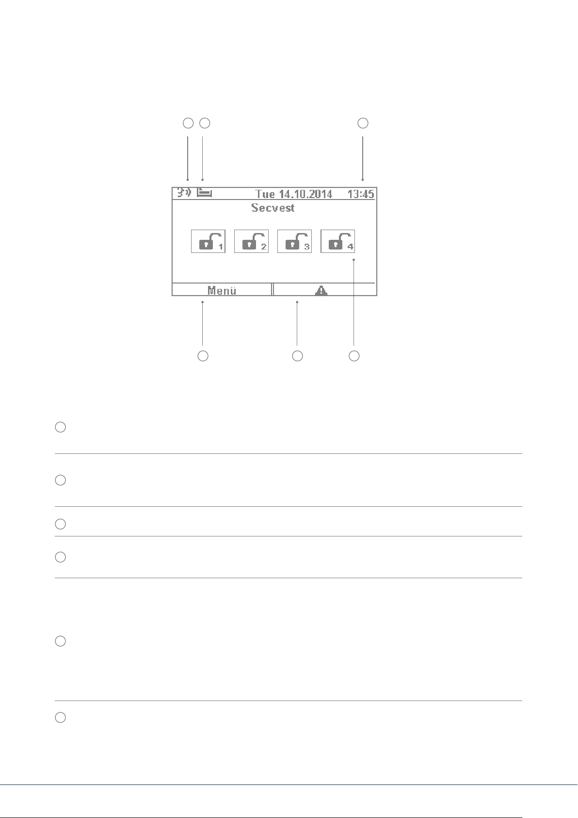
6. SECVEST DISPLAY
1 2 3
6 5 4
Voice message This symbol is displayed when a voice message has been recorded (for example, a
1
reminder from another user). Aer the alarm panel has been disarmed the user receives the following
audio message: "You have a message". The message can then be played back and deleted if desired.
Symbol for activity monitoring. This symbol is only displayed when activity monitoring is active.
2
This function is used for monitoring vulnerable persons and must be congured by the specialist
installation contractor.
3
Display of time and date
Display of the status of up to 4 sub-areas: open padlock = system disarmed, closed padlock =
4
system armed, house = internal arming active
Error symbol: indicates an alarm, reset, fault etc.
Note:
A "warning triangle" appears at the bottom of the display on the right-hand side if the alarm
5
panel detects a problem. The explanation (description of the problem) is not shown unless
an access level 2 (user) or access level 3 (installer) code is entered.
Aer a valid code has been entered the message appears in plain text (problem, fault,
warning, alarm etc.) The message is hidden again once the user has acknowledged or
conrmed it. The notication disappears automatically aer a one-minute time out.
6
Menu symbol: used to access the user menu
6. Secvest display
Page 13

7. MENU NAVIGATION AND OPERATION
Cursor control
The Secvest menu is mainly navigated using the cursor keys located below the display:
These keys are used to scroll through the menus and activate specic scenarios when the
system is being armed, amongst other functions. More information is provided in the
next chapter, "Arming and disarming the system".
A manual restart is initiated when the “upward” and “downward” navigation keys are
simultaneously pressed for more than ve seconds. For details, see section 16.1 Manual restart
These keys are used to select menus or symbols, change values and also exit the menus again. The
function of both keys adapts dynamically to the text shown on the display. If, for example, "Menu"
is shown on the le side of the display, press the
brings you to the user menu which you can exit again by pressing the key.
key below and enter your user code. This
The cleaning mode is started when the le and right navigation keys are pressed simultaneously.
For details, see section 10.5.1 Functions - Cleaning mode
Note:
It is not possible to use the alarm panel during cleaning; this is especially true for the double key
functionality (re, intrusion, medical emergency, care).
8. ARMING AND DISARMING THE SYSTEM
8.1 Arm/disarm keys
The arm/disarm keys for the alarm panel are located below the cursor eld. These keys can be
used to quickly and conveniently arm or disarm the alarm panel. Additional arming options are
covered in detail below. In the standard conguration, Secvest is armed on a time delay, meaning
it is only armed aer the exit delay programmed by your specialist installation contractor has expired.
This key is used to start "internal arming". Only the detectors for "perimeter protection"
are activated, so that you are still able to move around the building freely (even if there
are motion detectors installed indoors, for example).
7. Menu navigation and operation | 8. Arming and disarming the system
13|1212
Page 14
This key is used to quickly arm the complete system. No user code is required for this. Note that when
this key is pressed ALL detectors including those in all sub-areas (if there are any) are activated. This
function will only work if the key has been enabled in consultation with your specialist installation
contractor. This key has no function if it has not been enabled beforehand. If necessary speak to
your installation contractor if this key function is required.
This key is used to disarm the system again. Aer the disarm key is pressed you must enter
a valid user code. The complete system is then disarmed (including all sub-areas).
8.2 Graphical display of arming/disarming on the display
This section contains information on how the arming or disarming of the alarm panel is shown on the
display. This assumes that your system has been congured with just one partition. All detectors are
therefore assigned to partition1. In this case partition1 is the entire premises.
8.3 Arming/disarming via the quick arm keys
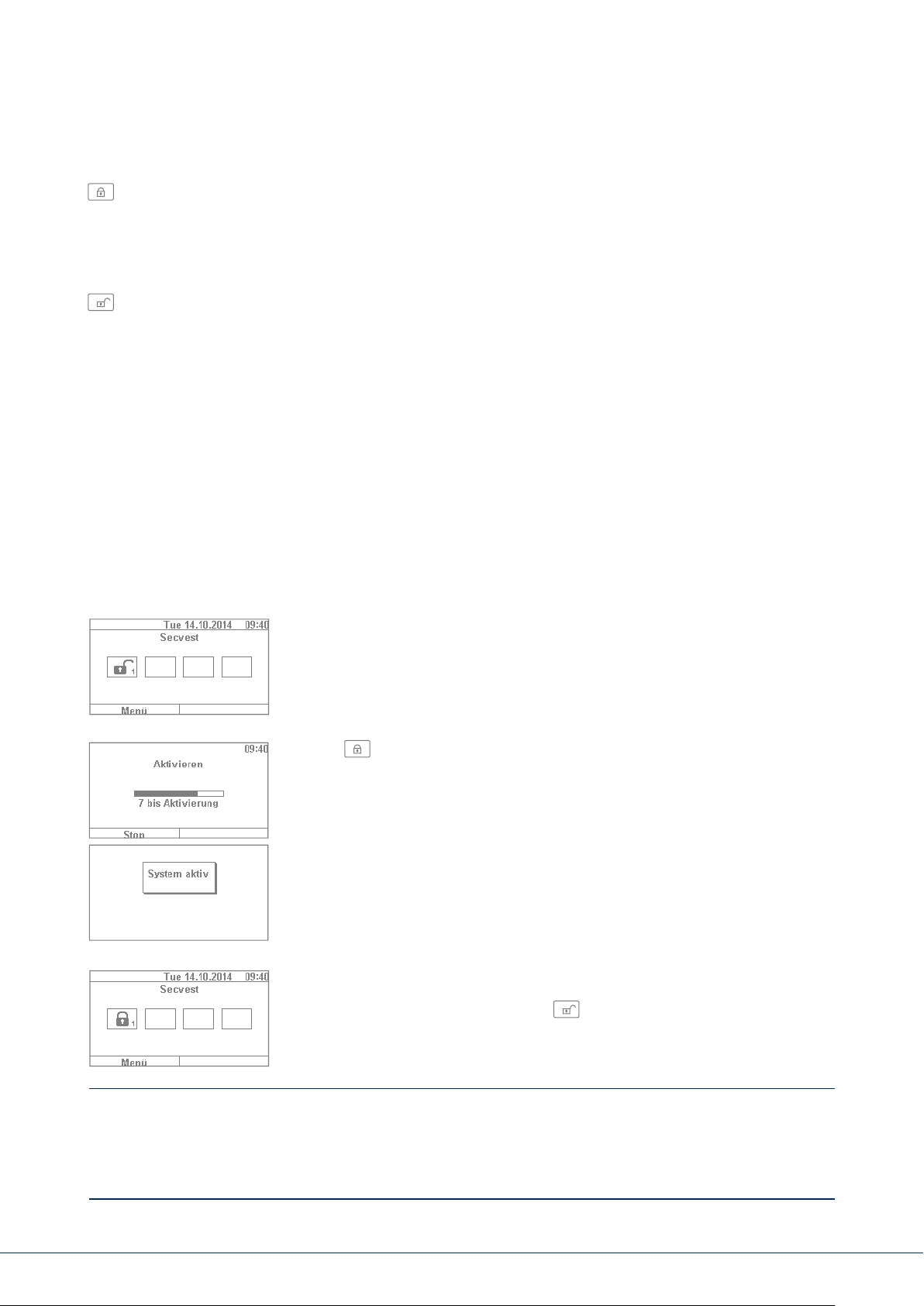
1. If the system is disarmed, the display responds as follows: The open
padlock symbol indicates the disarmed status of the alarm panel.
2. If the key is then pressed, the system is completely armed.
As mentioned previously, the system is armed only once the delay
time has expired as programmed by your installation contractor.
3. You should leave the premises within this time delay. The closed padlock
symbol then indicates the armed status of the alarm panel. To disarm the
alarm panel again, simply press the key and enter a valid user code.
The system is then disarmed with the audio message, "The alarm system
is disarmed" and the open padlock symbol visually indicates this status.
This method of arming the system as described here using the quick arm keys is one of the fastest and
provides a representative example of how system arming works in general. The next section provides
information on other ways to arm the system. Not all of these options may be available, as they
depend on the conguration of your system by the specialist installation contractor. If necessary
speak to your installation contractor if you desire a specic method of arming your system.
8. Arming and disarming the system
Page 15
8.4 Arming via the user code
1
4
7
*
2
5
8
0
3
6
9
#
The system can be armed by directly entering a user code.
The system has either been congured with a 4 or 6-digit user
code in consultation with your specialist installation contractor.
This code should be changed during commissioning, however. If a new user is added, a separate code
is created for this user. Every user should take note of their individual codes.
1. To arm the system, simply enter a user code. Please note that the "menu"
key is not pressed before entering this code. Otherwise you will be directed
to the user menu, from which you cannot arm the system.
2. Aer the code is entered the "delay time" starts (in the standard
conguration of the system). You should leave the building within this
time delay. For this reason, ensure that sucient time is planned to exit
the building. If, for example, 35s has already passed and you still have to
get out the door, there is not enough time. A false alarm may be triggered,
as the opening and closing of the door takes a bit of time in itself.
3. If the delay time has expired, the system is armed: you have now
successfully armed partition1 and can disarm it again by entering
a user code.
If a window is still open, for example, when the alarm panel is armed, an error message is displayed.
Correct the error (close the window) and then rearm the alarm panel. If the error cannot be
corrected, you can arm the alarm panel anyway by pressing the "Lock all" key. In this case the
alarm panel is armed with "hidden zones". This means that all open detectors or detectors with
faults are ignored during monitoring. These detectors will not trigger an alarm in this case!
These zones only remain hidden until the next time the system is armed.
8. Arming and disarming the system
15|1414
Page 16
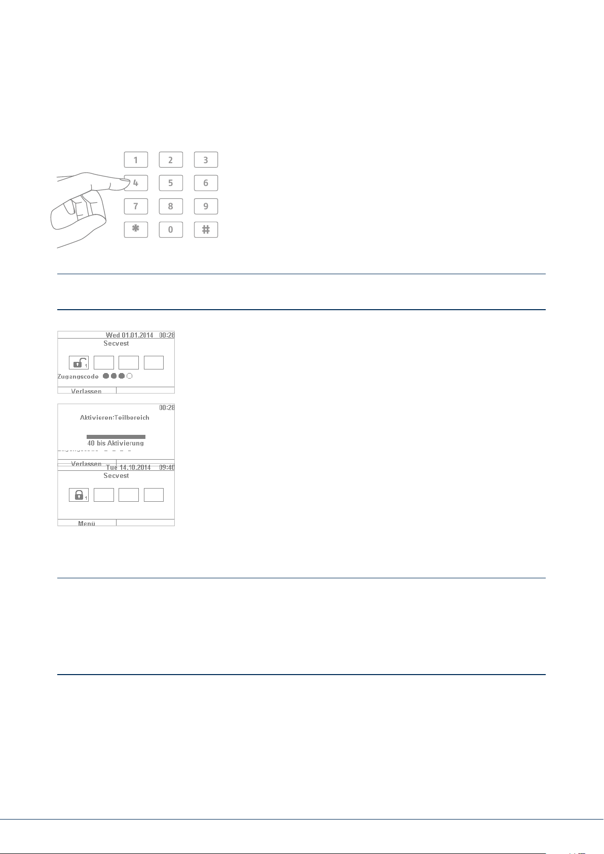
8.5 Arming sub-areas
In addition to the option of arming a partition via a user code, the system can also arm additional
sub-areas. The procedure for this is given here using the user code entry example. This function must
be precongured by your specialist installation contractor.
Aer entering the user code, you are asked to conrm which partition(s) you wish to arm. Alternatively
you can also arm the complete system when, for example, you plan on leaving the premises.
1. In our example, the alarm panel is divided into 4sub-areas. These
are displayed as disarmed by the open padlock symbol. First enter
your user code as usual.
2. Once the user code has been entered, the menu changes as follows:
3. Select “Change” and the display changes as shown in the gure
on the le. Click “Done” to arm all sub-areas. The system is now
completely armed.
4. If you only wish to arm certain sub-areas, click on “Change” and use
the key to navigate through the four sub-areas until the partition
youwish to arm is selected. Click on “Done” to arm the selected partition.
Repeat the same procedure to arm other sub-areas.
8. Arming and disarming the system
Page 17
8.6 Individual sub-areas
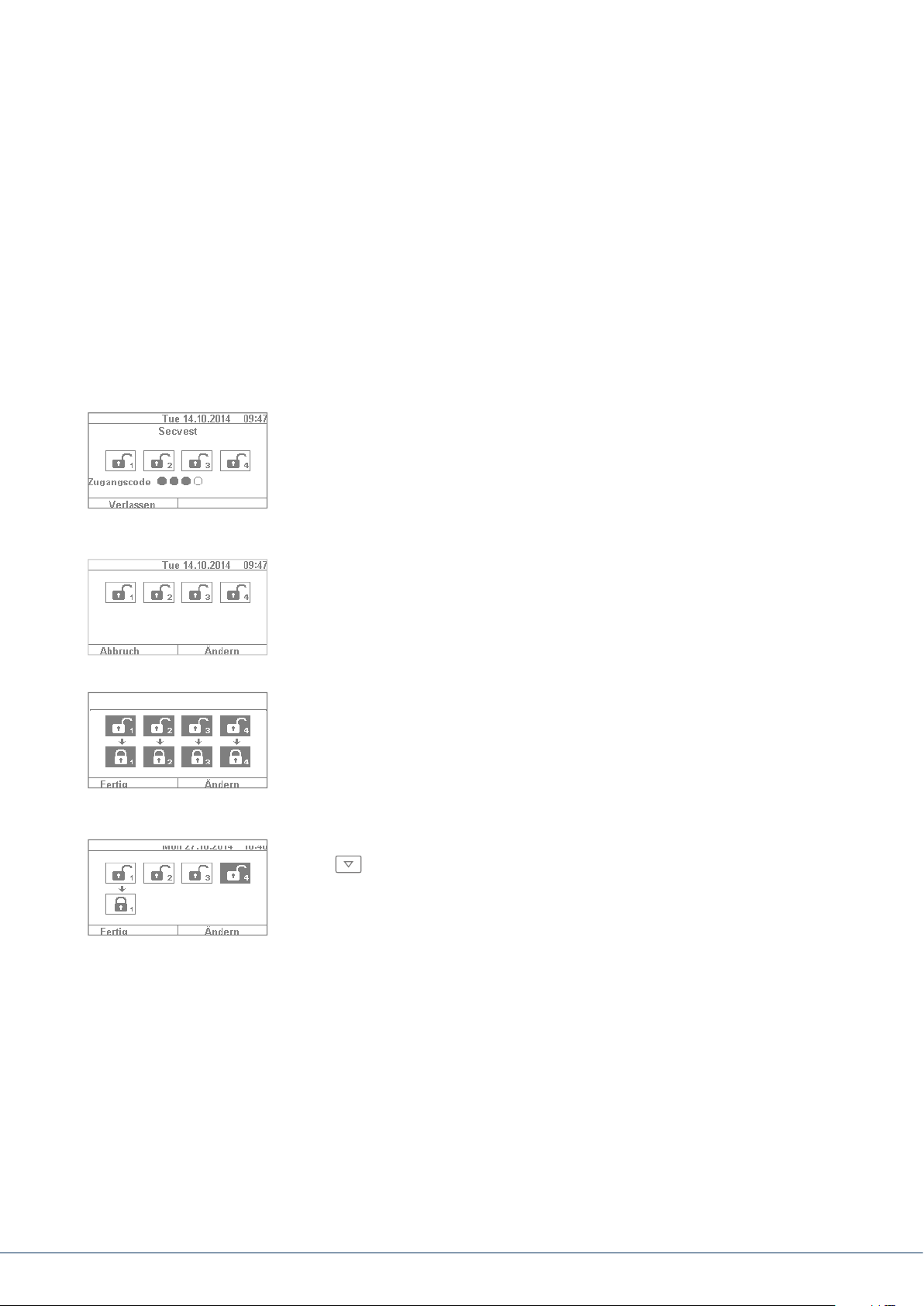
1. If you wish to arm two sub-areas, proceed as follows: enter your user code.
Using the arrow keys, select the two sub-areas to be armed. The
selections are visually highlighted. Set the selected sub-areas to the
open padlock symbol via the "Change" function. Leave the sub-areas you
do not wish to arm "empty". In this case the menu looks like the example
given in the gure on the le.
2. Click on "Done" and system sub-areas 1 & 3 are armed, while sub-areas
2 & 4 remain disarmed. Aer the arming time, the Secvest display then
looks like the example given in the gure on the le.
3. To arm only partition2, repeat the steps as described above. Select
the individual sub-areas, click on "Change" and set the value for the
partition to "empty" as shown in the gure. The partition to be armed
(partition2 in this case) should be set to "active" using the "Change"
function. Click on "Done" to arm just this partition.
8.7 Internal arming
In addition to the option of arming the complete system and sub-areas, the system also oers the
option of "internal arming". This type of arming is preferred when occupants are home and wish
to arm just the perimeter of the premises. Certain detectors indoors (such as motion detectors)
are disabled so that occupants can move freely within the building. A practical example here is
application in a private home.
The following options are available for internal arming:
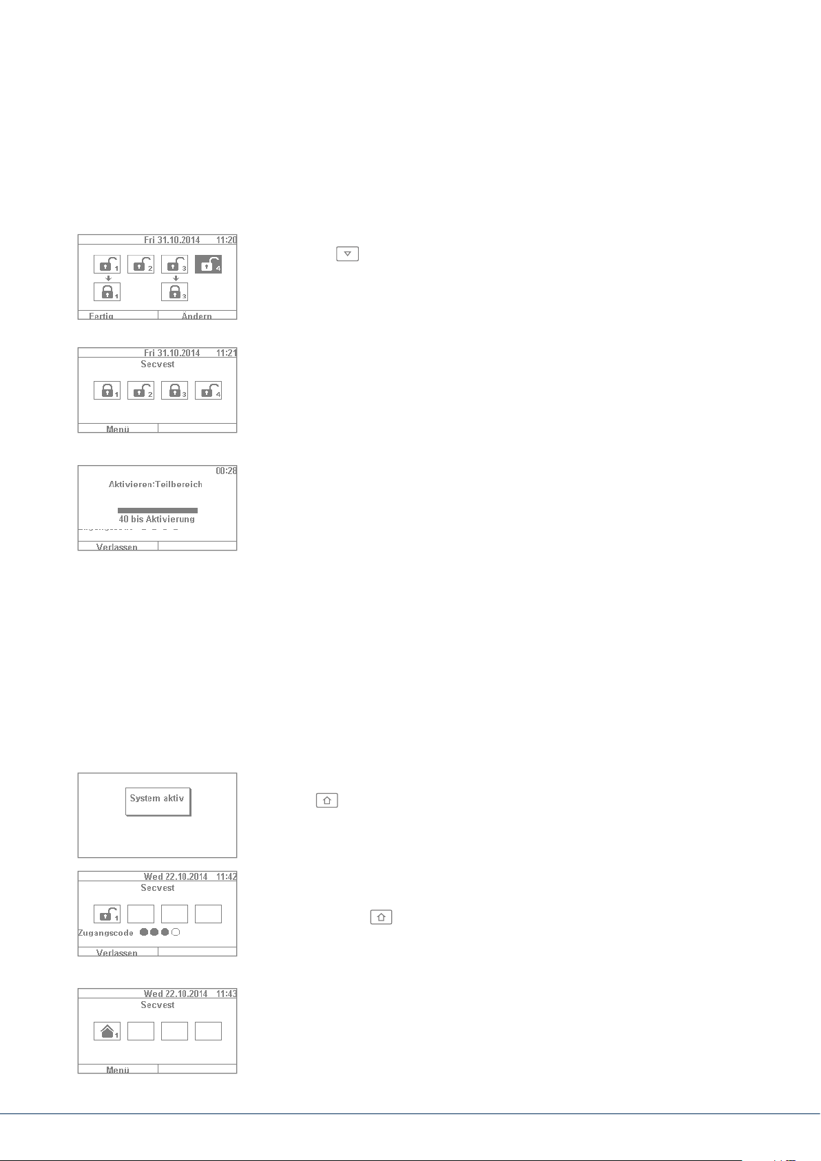
Option 1:
Press the key to internally arm the system with just one touch.
The quick arm option must be enabled in advance by the specialist
installation contractor.
Option 2:
Enter a user code to arm the system. Click and hold "Change" until
the house symbol appears. Click on "Done" and the system is
"internally armed".
You can now move freely around the house even though motion detectors
may be installed. The perimeter of the premises is armed, so that an
intruder attempting to break in from outside triggers an alarm.
8. Arming and disarming the system
17|16
Page 18

8.8 Internal arming via chip key
The procedure for internal arming via the chip key is virtually the same as arming
the complete system: Hold the chip key in close proximity to the ABUS logo and
swipe it over the logo briey. A prompt appears, requesting conrmation on the
type of arming required. Click on "Change" as usual and select the house symbol.
Click on "Done" to arm the system internally.
8.9 Internal arming via remote control
On the remote control, the * key is assigned the "internal arm" function as
standard. This symbol is on key2 of the remote control. Press the key and the
system is internally armed. Visual feedback is provided next to the * symbol:
brief ashing (green) for sending the signal, then ashing (red) to indicate
successful internal arming.
8.10 Arming via wireless control panel
An additional way of arming the system is provided via the optional wireless
control panel. This arming/disarming option is as similar as possible to the
other system options. Only the operation method is
control panel does not have a display. Please read the individual operation
options in the user manual for the wireless control panel.
dierent, as the wireless
8.11 Arming via remote control
If there is a remote control, you can press the corresponding keys to arm/disarm
the system (all sub-areas are armed/disarmed simultaneously) and internally
arm the system if you as the user are authorised to do so. You can also check
the status of the system. The remote control provides visual system feedback
for all entries ("2WAY function"). For a detailed explanation of the individual
functions of your remote control, please read the user guide for the remote
control.
8. Arming and disarming the system
Page 19
8.12 Arming via chip key
The chip key can be used to completely arm and disarm the wireless alarm panel
(or a partition, if there are any) without touching the panel itself. The chip in
principle eliminates the need to enter a code. If you as the user to whom the chip
is assigned are authorised to arm or disarm multiple sub-areas, you must then
decide which area to arm aer you have swiped your chip key. The reader area for
the chip key is located at the height of the ABUS logo. You only have to swipe the
chip in the proximity of the reader area to arm the system – you do not have to
touch the housing.
1
2
3
4
5
6
7
8
9
0
*
#
8.13 Arming via delay times
If you enter a code directly on the alarm panel (or via chip key or quick arm keys), the following
"problem" occurs: You must still be able to leave the premises through the doors. If the system were
automatically armed, you would not be able to leave the premises without triggering an alarm, if you
have a magnetic contact on the doors, for example. For this reason there is a "delay time". The delay
times are precongured by your specialist installation contractor.
There are generally two delay times:
• Exit delay
• Entry delay
The exit delay is set to 40s as standard (the time can be adjusted by the specialist installation
contractor according to your needs, however). Following the start of the exit delay, the premises
must be le within this time.
Ensure that all windows and doors etc. are closed rst before activation.
8. Arming and disarming the system
19|18
Page 20

Aer the start, a continuous tone sounds.
Make your way out of the building and open and close the doors in time.
The continuous tone is replaced by a pulsed tone when the door is opened/closed.
It will then return to a continuous tone.
The system also allows a special type of exit delay. the system is only armed once the
doors are closed. The exit delay is therefore exible to allow you to take whatever
time you need to get out the door. Speak to your specialist installation contractor
if you desire this type of arming.
Important: if the exit delay has expired and you are still inside the building, your movement,
for example, will trigger an alarm if detected by a motion detector.
The entry delay gives you a sucient timeframe to disarm the system aer opening the doors when
the system is armed. The entry delay should also be programmed in consultation with your specialist
installation contractor. Ideally the entry delay should be as short as possible. If you enter your premises
through the doors, you should hear a pulsed tone. As long as this tone sounds you have time to disarm
the system. Disarm the system using your code (or chip key/disarm key).
Important: if the entry delay expires without the system being disarmed, an intruder alarm is triggered.
8.14 Preventing arming of the system
The alarm panel prevents arming in the following circumstances.
Intrusion detectors (apart from the entrance) are open.
Once they have been closed the arming procedure starts.
A panic button or panic transmitter has been triggered.
The system or a component or detector/zone is showing tampering.
If communication or signalling devices have faults,
this would prevent transmission of notications.
A supervision shutdown in a wireless component
The user can override permissible events (shutdowns).
8. Arming and disarming the system
Page 21
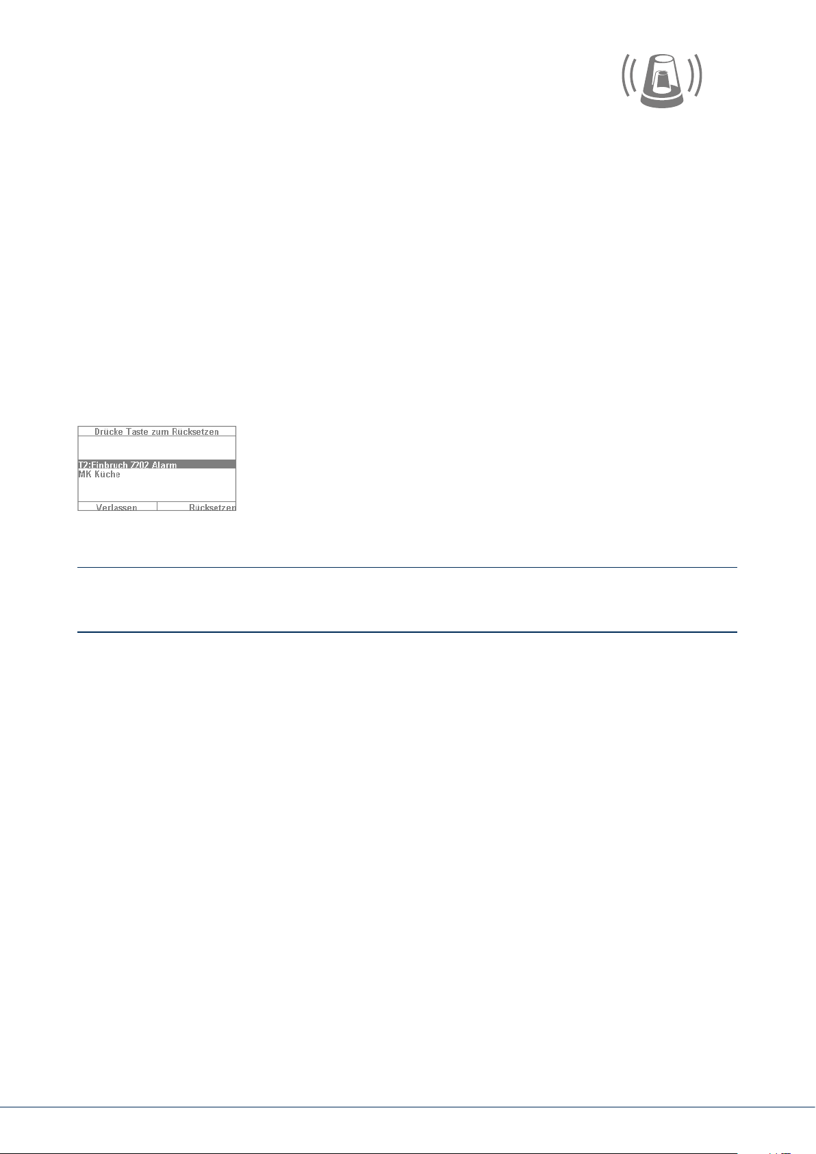
9. RESPONDING TO AN ALARM
First of all: remain calm. An alarm does not always mean anintrusion. Sometimes an alarm is caused
by something else, such as a self-triggered false alarm. For this reason, get a feel of the situation rst
and then respond accordingly in a composed manner. Disarm the system, check the reason for the
alarm and then reset the alarm.
If an alarm is triggered, rst disarm your alarm panel by entering a user code, for example. You will
then be prompted to "reset" the alarm panel. This means that you must still "acknowledge" the alarm
on the system in order for it to be ready for operation again.
The alarm is then shown on the display. "T2" means that an alarm has been triggered in partition2.
“Intrusion Z202 alarm” means that an intruder alarm has been triggered in “zone202” in this partition.
This "zone02" is the second detector in the system, with the name "MC kitchen" (magnetic contact in
kitchen). You can now go into the kitchen to see what exactly has happened near this detector.
If the cause of the alarm is claried and corrected, press "Reset".
The system is then reset and ready to be armed again. Note that a
reset is necessary. If this is ignored (e.g. if you press "Exit") the reset
does not take place properly and appears automatically during the next
arming process. If no entry is made, the graphical display disappears aer
1minute but remains on the system.
Important: occasionally you may nd that an alarm cannot be reset. This may occur, for example,
if the housing of your alarm panel and its components have been opened and a tampering alarm
has been triggered. This can be corrected only by your specialist installation contractor.
9.1 Alarm types
An alarm can have various causes. The following alarms exist in principle:
• Tampering alarm
• Intruder alarm
• Panic alarm
• Technical alarm
• Fire alarm
• Emergency call or medical emergency alarm
• Entry delay exceeded
• Exit delay exceeded
The Secvest has four dierent types of alarm. Depending on the status of the system (disarmed, armed,
internally armed), the following alarms are available (depending on the setup or programming of the
alarm panel):
9. Responding to an alarm
21|20
Page 22

Internal Local External Silent
Alarm panel siren
Indoor siren
Outdoor siren
Wireless control panel
Information module
Visual alarm, such as ashing light
Diallers, such as monitoring station switching, text mes-
sage, email, etc.
Relay üopt. üopt. üopt. üopt.
ü ü ü
ü ü ü
ü ü ü
ü ü ü
ü ü ü
ü ü ü
üopt. üopt.
ü ü
–
–
–
–
–
üopt.
9.2 Alarm forwarding
If the communication interface of the Secvest has been programmed (speak to your specialist installation
contractor),
your system and the connection used, such as IP, PSTN):
• Alarm forwarding via telephone (analogue or VoIP)
• Alarm forwarding to a monitoring station (MS)
• Alarm forwarding via email
• Alarm forwarding via text message
• Emergency call: emergency switching to medical services (e.g. Tunstall)
the following alarm forwarding options are available (depending on the conguration of
9.2.1 Alarm forwarding via telephone
With alarm forwarding via telephone you receive a telephone call and hear a message (recorded by
you or the specialist installation contractor), for example: "Intruder alarm at bathroom window.
Please arrange help." Proceed as follows:
1. The call occurs on the telephone and is displayed there like any other call.
2. Accept the call.
3. Listen to the entire message. The message is dierent depending on the cause of the alarm.
4. The recorded text is repeated three times. Aer the third time, the microphone on the alarm
panel is enabled and you can listen to what is happening in the room. You also have the
following key commands available (your telephone must be DTMF-compatible):
Telephone key (DTMF) Meaning
Listen 1
Speak 2
Toggle between "Listen" and "Speak" *
Playback messages 3
End call 5
End all calls 9
9. Responding to an alarm
Page 23

5. If you feel capable of resolving the problem yourself, acknowledge the alarm transmission by pressing
5 or 9. 5 means that the attempt to call you is stopped. Other contact numbers on the system may be
called, however. 9 means that the attempt to make any calls is stopped. No other contacts are called.
6. If you cannot resolve the problem yourself, press 5 in any case. The alarm is forwarded to additional
people.
You can “remotely control” the alarm panel via the telephone keypad
(if this function is enabled). For more information, see "Advanced system operation".
9.2.2 Alarm forwarding to a monitoring station
If switching to a monitoring station is implemented, the monitoring station (MS) takes care of
acknowledging the alarm transmission and coordinating help. Speak to your specialist installation
contractor if you have questions about monitoring station switching.
9.2.3 Alarm forwarding via email
If the Secvest is connected to the internet (e.g. via a router), it can also forward an alarm via email.
The alarm panel text (e.g. "Intrusion Z01 alarm") is sent to a predened email address. If you are also
using the Secvest PIR camera, the alarm image can also be attached to the email. Contact your specialist
installation contractor if you wish to set up this function.
9.2.4 Alarm forwarding via text message
Similarly to email transmission, alarms can be forwarded via text message (for example,
using the optional wireless mobile module).
9.2.5 Alarm forwarding in the event of a personal or medical emergency
If your household includes a vulnerable person, you can also set up forwarding for local alarms to a
monitoring station specialised in handling medical emergencies. Speak to your specialist installation
contractor about setting up this function.
The user menu helps you congure certain basic functions of the system. You can create and manage
users, set the date and time and add and remove contacts.
9. Responding to an alarm
23|22
Page 24
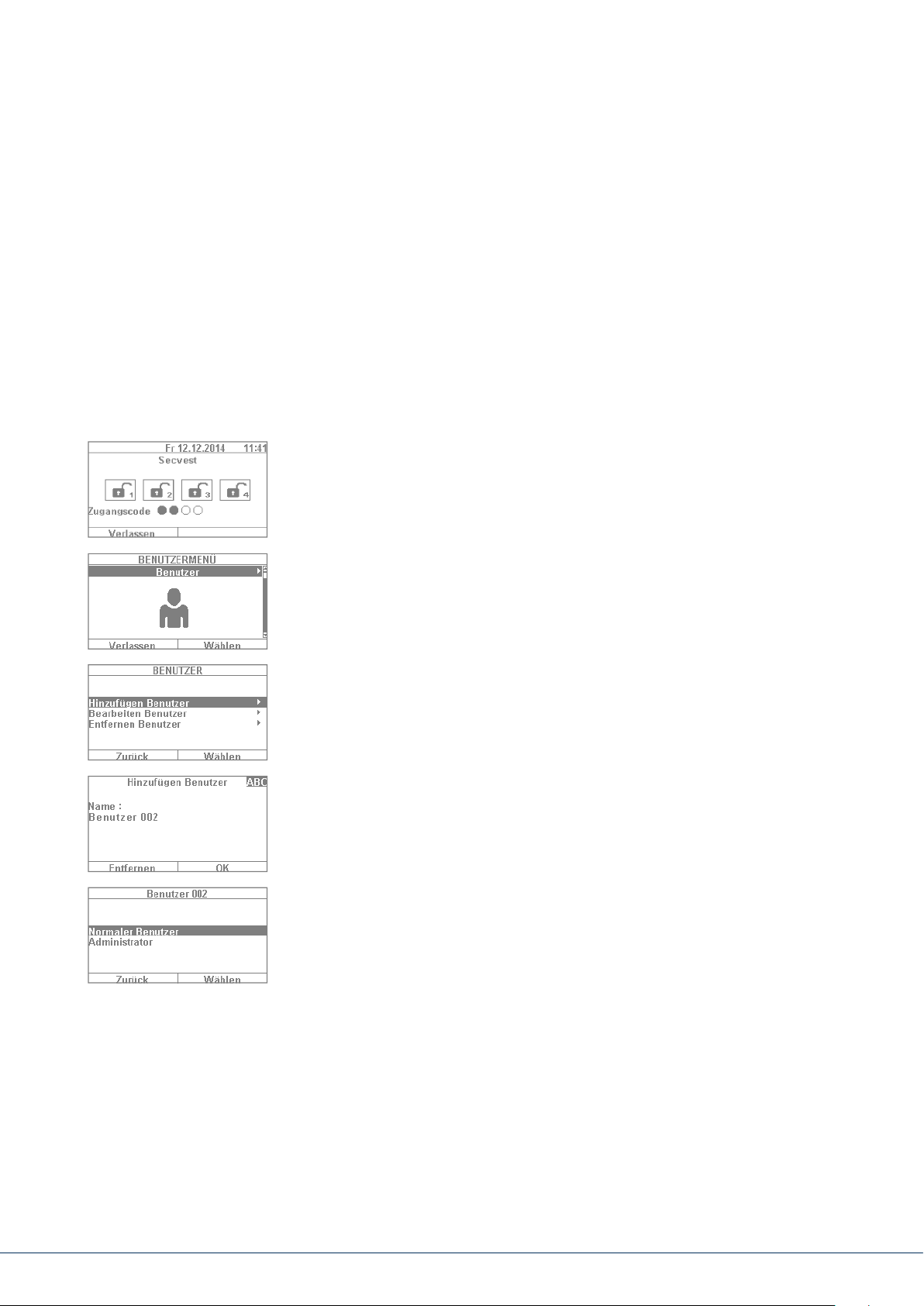
10. USER MENU
10.1 Users
There are two dierent "levels" of the user menu. Log in as an "administrator" to delete other users,
for example. Log in as a "normal user" to use the system with limited options in certain menus –
you cannot edit or delete other users in this mode. Certain menus are not accessible for "normal users",
such as "Contacts" and "Info". The administrator is in charge of managing these menus.
The following contains an overview of the structure of the user menu and the options provided
by these menus when you are logged in as an administrator:
1. To log into the user menu, select "Menu" and enter an admin code.
The rst menu appears.
2. As a system administrator you can manage users and create new users.
Log into the user menu with your admin code and go to the "Users" menu.
3. To add a new user, select "Add user". You are then guided through
the setup options for a new user step by step.
4. User name: Using the Secvest keypad, enter the name of the user.
5. Select which user level the new user will have: Normal user: a normal user
has limited options compared to an administrator. Normal users cannot
create new users or edit existing users other than themselves, but they
can change their own codes and assign remote controls, for example.
Administrator: an administrator has advanced options in the user menu.
Administrators can create new users and edit existing users. There are
also more advanced options in other menus, such as in the system
conguration. Usually one administrator per household is sucient.
If the premises involve a commercial property with multiple employees,
for example, it may be a good idea to create additional administrators.
10. User menu
Page 25
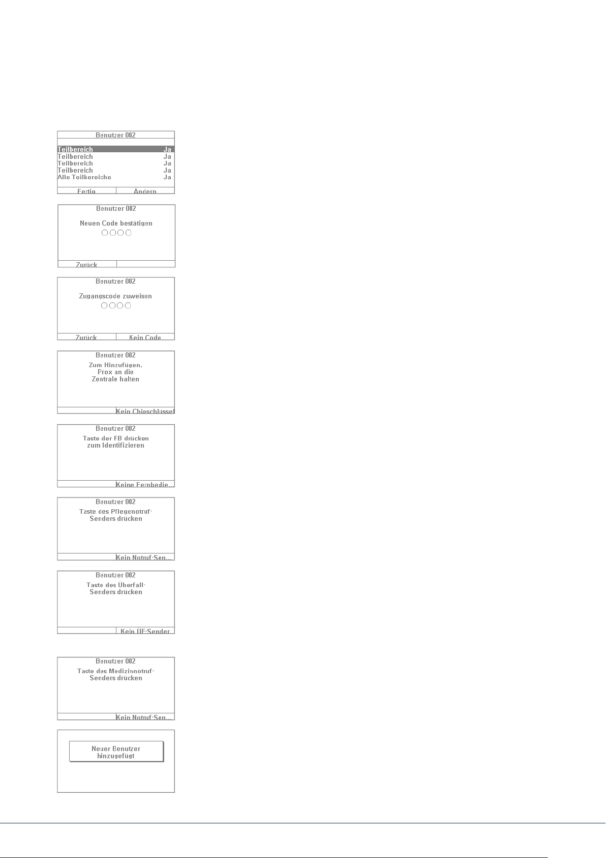
6. The next step involves assigning arming/disarming authorisation for
sub-areas. Select "Done" if the user will be authorised for all 4sub-areas.
Otherwise make adjustments using the "Change" function.
7. Assign an access code. This code should ideally be changed by the user
themselves and kept safe by them. Ensure that the code is "secure".
Code combinations such as "5678" are less secure than "2671", for
example. For a higher degree of security, the system can be precongured
to accept 6-digit codes. Speak to your specialist installation contractor if
your system is congured for only 4-digit codes. A 4-digit code is created
in this example. This code must be conrmed once aer it is rst entered.
Alternatively you can also select "No code". In this case the user can only
arm the system via chip key or remote control.
8. Additional components can be assigned to the new user. The rst prompt
is for a chip key. Take the chip and swipe it across the ABUS logo in close
proximity to the housing. If no chip key is desired, select "No chip key".
9. A remote control can then be assigned. Press any key of the remote
control. If no remote control is desired, select "No remote control".
10. Nursing emergency call if your household includes a vulnerable person,
you can give them a mobile emergency call button. This button is used
to trigger an internal alarm quickly if the person needs help. Press the
nursing emergency call button key once to assign it.
11. Panic alarm button: you can also use the emergency call button as a
panic alarm button. Note that if the button is already being used as an
emergency call button, it cannot also be used as a panic alarm button at
the same time.
12. Medical emergency call: you can also use the emergency call button/panic
alarm button as a medical emergency call button. Note that if the button
is already being used as a emergency call button or panic alarm button, it
cannot also be used as a medical emergency call button at the same time.
13. The following conrmation then appears: "New user added".
You can create additional users in the same way.
10. User menu
25|2424
Page 26
Proceed as follows via the web interface:
Log in as an "administrator", click on “Users” on the right hand side and then click on “Add user”.
You can now specify a name, type, code and partition.
Then login with the access details that have been set or the user details for this user and
add “Chip key”, “Remote control”, “Panic alarm”, “Medical pendant” and “Care pendant”.
Follow the instructions on the display.
10.1.1 Editing users
Here, the administrator can edit existing users.
Use the cursor keys to select the user to be edited. Then select “Edit user”.
The administrator can only change the name, type and partition for other
users.
The administrator can select and edit their own “Name”, “Code”, “Chip key”,
“Remote control”, “Panic alarm”, “Medical pendant” and “Care pendant”.
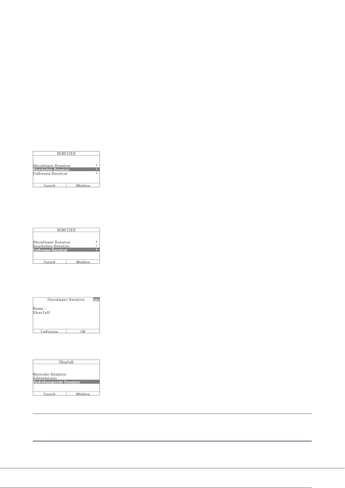
10.1.2 Removing users
To remove users (such as an employee who has since stopped working
at the premises), select the user in question and remove them from the
system. All components assigned to this user, such as remote controls,
are automatically deleted.
10.1.3 Creating a user "threat code"
In addition to the user levels of "normal user" and "administrator" you
also have the option of creating a "threat code". This code is used to
seemingly disarm the system during a hold-up when the intruder is
watching. A silent alarm is still triggered in the background, however.
For this function to be enabled, an appropriate communication interface
(e.g. telephone or monitoring station switching) must be set up. The steps
for setting up a threat code user are the same as those for setting up any
other user. Proceed as follows:
User menu -> Add user -> Name -> "Threat code user". Create a code for
this user. This code should be known to all users of the alarm panel. Then
if an intruder enters the premises and forces you to disarm the alarm panel,
simply enter this "threat code". The system appears to disarm as normal.
The silent alarm is triggered via telephone switching, however.
Important: Your specialist installation contractor must enable the function beforehand to make the
"User threat code" option appear in the user menu. If in doubt contact your specialist installation
contractor if this option does not appear in the menu.
10. User menu
Page 27

10.2 Voice memo
10.3 Hiding zones
This function is used to leave someone else a message ("Memo function").
Record a short reminder, for example, and then arm the system. The next
person to disarm the system is notied with the text "You have a message"
and a corresponding symbol. Select "Recording" to record a 30-second
message and then save it. Any user can delete this message aer it has
been played back. This function can be completely disabled in consultation
with the specialist installation contractor.
It may occasionally be necessary to exclude a detector (also called a "zone")
from monitoring, for example if a detector is faulty or a zone cannot be
closed for some reason. The system then indicates the detectors that can
be hidden. The settings mean: Ü = monitored and G = locked (not
monitored). Select the detector to be hidden and press "Change". Note
that detectors to be hidden manually must rst be congured for this
function by the specialist installation contractor. For this reason not all
of the detectors in the system may appear in the list of detectors which
can be hidden if this has been set up that way beforehand. If detectors
are hidden, they are no longer monitored when the alarm panel is armed.
A hidden detector is "unhidden" the next time the system is disarmed and
must be hidden again manually to be excluded from monitoring the next
time the system is armed, if desired.
Using the web interface, it is also possible to hide zones. This requires
selecting the “Hide zones” button, which will open a list of all the zones
which can be hidden.
10. User menu
27|26
Page 28

10.4 Outputs on/o
If your installer has congured the outputs as the “user dened” type, you can switch
them on and o here.
10.5 System configuration
The following settings can be dened in the system conguration:
• On/o functions: settings for certain special functions such
as door bell and voice messages.
• Date & time: setting for the date and time
• Remote controls: reprogramming of key assignments for remote controls
• Volume settings: setting for the volumes of dierent tones and messages
• Web access: activation/deactivation of web access
• Time schedules active/inactive: Conguration of time schedules for
automatic arming/disarming
10.5.1 On/o functions
Select “Functions” to access the following options. These options will be
claried in the subsequent sections.
Key front menu Touch front menu
Bell Bell
Voice message Voice message
Activity monitor Activity monitor
Display contrast Display contrast
Backlighting brightness Backlighting brightness
Backlighting for menu keys < hidden >
Backlighting for arm keys < hidden >
Backlighting for number keys < hidden >
Zone name announcement Zone name announcement
Restart Panel
Administrator only
S/W >=1.01.00
hidden for normal users
Restart Panel
Administrator only
S/W >=1.01.00
hidden for normal users
Keypad tones Keypad tones
< hidden > Dynamic backlighting
< hidden > Cleaning mode
10. User menu
Page 29

Bell
If the "Door bell" property is congured for a detector (e.g. for a magnetic contact at the entrance of
a business), the disarmed alarm panel triggers a tone similar to a door bell. This function must be
congured by the specialist installation contractor. This indicates that someone has entered the
business premises. If you wish to disable this function for a certain time period, it can be disabled here.
Voice message
In this menu you can disable the audible messages on the alarm panel (e.g. "Please note
the message on the display").
Activity monitor
If the "Activity monitoring" property is congured for a detector (e.g. a motion detector in the hallway),
the function of a motion detector can be "reversed". This function must be congured by the specialist
installation contractor. If the function is reversed, an emergency call alarm is sent aer a dened time
period in which no movement has been detected. This function is used to monitor older, vulnerable
members of the household. Aer a dened time period, an emergency call is sent when the regular
"presence detection" at a previously designated motion detector has not triggered. This allows vulnerable
members of the household who generally spend their time moving around a specic room to receive help
quickly if their "presence" is not detected aer a certain time due to a fainting spell or something similar.
Display contrast
Change the contrast of the Secvest display here.
Backlighting brightness
Change the display brightness setting. You can select "low", "medium" or "high".
LCD backlighting / backlighting
LCD backlighting
Only visible if the key front is installed. Here you can set the illumination of the display.
⋅ “O” turns the illumination o
⋅ “On” web access enabled
⋅ “When active” web access enabled
10. User menu
29|28
Page 30

Backlighting
Only visible if the touch front is installed. Here you can set the illumination of the
complete touch front. LCD backlighting, menu keys, arm keys and number keys
⋅ “On” turns the illumination on in order to keep the complete touch front lit con-
stantly.
Note: LCD backlighting and all backlighting of the keys are always turned on. The wakeup function
is deactivated. In case of a power failure, the illumination switches to “When active” in order not
to use unnecessary electricity from the battery.
⋅ “When active” means that the illumination of the complete touch front only remains on
for approx. 30s aer each use. It then turns o automatically.
Note: Wakeup function is activated. The illumination is rst turned on when a button is pressed (rst
touch). No other action results from a “rst touch”. From the second touch on, the keypad functions
as normal. The user can then touch one of the visible symbols (house/padlocks). At the first touch, the
alarm panel will not perform the functions associated with these buttons. At rst, only the illumination
is turned on.
Backlighting for menu keys/backlighting for arm keys/backlighting for number keys
Only visible if the key front is installed. The same setup as for "LCD backlighting" applies here for the
backlighting of the menu keys, arm/disarm keys and number keys. Set the desired lighting of the keys
for menu navigation here.
Note: If the touch front is installed, these 3 menus are hidden.
Zone name announcement
Your detectors can be equipped with an additional audio message if desired. In consultation with your
specialist installation contractor, the detectors are usually already given a name, for example "MC living
room" for "magnetic contact in living room". This text can be recorded and saved here individually for
each detector, with approx. 2s allocated for each detector. If detector "MC living room" triggers an alarm,
for example, the text not only appears on the display when the alarm is disarmed, but the name of the
alarm is also audibly played back. Do not forget to select "Playback" aer recording the detector text to
check what was recorded and ensure it is correct and intelligible.
Voice message 2 second announcement for each zone
If this function is activated:
User menu -> Conguration -> Functions -> Zone name announcement ->
Enabled on and zone names are spoken, an additional announcement is made:
10. User menu
Page 31

For an open zone
“The alarm system cannot be armed” + “<Zone name>” For several open zones,
the zone with the lowest zone number will be announced in addition.
During an alarm
⋅ Voice dialler Following an “individual message” and “Message x”,
the zone rst triggered will be announced in addition.
⋅ Alarm panel The zone rst triggered will be announced with each partition.
The partition with the lowest number will be rst.
Example:
Alarms were triggered in the following zones in the following order:
Zone 226 Partition 3
Zone 225 Partition 1
Zone 203 Partition 1
The following can be heard over the system:
“The partition is deactivated! Important! An alarm was triggered!
<Zone 225 voice message>, <Zone 226 voice message> Reset required“
Restart Panel
You can use this to restart the alarm panel manually.
This is helpful for some problems, to reset the alarm panel to a dened initial state.
All the settings and congurations are retained.
Note: This menu item is only visible to the administrator, i.e. the administrator must
be logged into the system.
A restart is only possible when
• all partitions are "disarmed" and
• the alarm panel has completed all important communications, transmissions and actions.
Select "Restart alarm panel" by pressing the "Change" menu key.
You are prompted for conrmation.
Press the "Yes" menu key.
At this point you can still cancel the restart.
Press "Back".
There are more details in Section 16.1, Manual restart (switching o and switching back on).
Keypad tones
When “On” is selected, a clicking sound via the loudspeaker is generated by pressing or touching each key.
10. User menu
31|30
Page 32

Dynamic backlighting
Only visible if the touch front is installed.
The brightness regulation is an option for dynamic light control.
If the “Dynamic backlighting” menu item is set to “O”, it will behave similarly to
the Secvest with a key front with a xed “high”, “medium” or “low” value.
If the “Dynamic backlighting” menu item is set to “On”, the backlighting will adjust
proportionally to the ambient light.
The high, medium and low settings still have an inuence on the level and
degree of the increase. The minimum and maximum values are:
Backlighting brightness Minimum values Maximum values
High 15% 100%
Medium 10% 50%
Low 2% 11%
Cleaning mode
Only visible if the touch front is installed.
“O” deactivates the cleaning mode.
“On” enables the cleaning mode.
The cleaning mode (factory default “On”) is started when the le and right navigation keys are pressed.
The keys are disabled for a total of 35 s. You can now clean the front without accidentally triggering an
action. The display shows “Cleaning mode”. An acoustic warning signal and notication on the display
during the last 5 s signalise that the keys will shortly function as normal. The display will show: “End
of cleaning mode”
Note: It is not possible to use the alarm panel when it is in cleaning mode; this is especially
true for the double key functionality (re, intrusion, medical emergency, care).
Cleaning mode will stop if an alarm occurs.
If an alarm occurs during cleaning mode, the cleaning mode will immediately
be aborted and the keypad will return to normal use at once.
If a nursing emergency call timer starts, the cleaning mode will be aborted.
A 30 s “abort time” begins when the nursing emergency call alarm is pressed.
If an inactivity warning timer starts, the cleaning mode will be aborted.
A 2 minute “abort time” begins when the care activity monitor establishes inactivity.
It is not possible to start the cleaning mode when an alarm is present.
10. User menu
Page 33

10.5.2 Date & time
Only visible to the administrator.
Set the time and date here. Both can be entered directly using the number keys. Click on "Next"
to navigate through the menu. Then dene whether the system automatically adjusts for daylight
saving time or whether you wish to adjust the system manually yourself. We recommend setting
it to adjust "Automatically".
Activating the check box on the web interface allows the times to be called up from an NTP time server.
Here, you can also set when the system should synchronise with the selected provider.
10. User menu
33|32
Page 34

User menu -> Conguration -> Date & time
SNTP Time sync.
SNTP active
O
On
Sync on start-up
O
On
Sync daily
O
On
Manual sync
(synchronises date/time immediately)
NTP server name
ntp.exnet.com*
Name:
ntp.exnet.com
pool.ntp.org*
Name:
pool.ntp.org
<empty>
<empty>
<empty>
(A list of 5 congurable
NTP-server names in order of priority.)
Manual mode
Set date
Set time
Summer/winter
Automatic
Manual
10.5.3 Edit outputs
Only visible to the administrator.
If your installer has congured the outputs as the “user dened” type and
as enabled editing, you can edit them here.
You can change the following:
Name of the output
Polarity
Continuous or pulse switching
Schedule
Event
- Up to 3 events can be assigned and edited.
10. User menu
Page 35

10.5.4 Remote controls
Only visible to the administrator.
Assigned remote controls can be edited or removed here. The following options are available:
• Edit: press the * key of the remote control to reprogram it. The standard setting of the key is
"Internal arming". If you wish to switch a relay output with this key instead, however, this
function can be assigned to this key. A suitable relay output must rst exist in the system.
Speak to your specialist installation contractor if you require this function, such as to open
the garage door via a relay output.
• Remove: remove a remote control that has been lost or is no longer needed. If you still have
the remote control, press any key. If you have lost the remote control, press "No remote control"
to delete it without having to press a key.
• Delete All you can delete all remote controls in the system at once here.
• Panic response: if the remote control has a panic alarm, this function can be disabled here.
The "panic alarm" on the remote control can be triggered by pressing both padlock keys
at the same time.
10.5.5 Volume settings
Only visible to the administrator.
Set the volume of dierent tones here. The tones can be changed by
directly entering a number from 0–9, where 0 means muted and 9
represents maximum volume.
Operation tones: refers to all tones that occur when the system is being
operated such as the feedback tones when operating the
system via the keypad.
Info tones: refers to all info tones, such as feedback tones for error messages.
Alarm tones: The volume of the alarm tones (intrusion, re, etc.) can be
changed here. The volume of the messages can be changed
by clicking “Select” and then adjusting the volume using the
+/- keys.
We recommend leaving alarm tones set to “9”. If you set the volume of the alarm tones too low,
you may not hear an alarm in time or at all.
10.5.6 Web access
Only visible to the administrator.
Dene whether or not your system can be programmed or operated remotely by the installer here.
• Disabled Web access disabled (admin, normal users and level 4 users still have access)
• Enabled Web access enabled
10. User menu
35|34
Page 36

10.5.7 Remote updates
Only visible to the administrator.
Dene whether your system can be remotely updated here. For details, see the installation manual,
“B/W upgrade” appendix
“Disabled” A level-4 user cannot update your alarm panel.
“Enabled” Approval is granted so a level-4 user can update your system.
10.5.8 Time schedule active/inactive
Only visible to the administrator.
You can enable the "week planner" in this menu. For example, if on Monday to Friday you want the system to disarm at 7a.m. and then arm at 6p.m. (a typical timeframe for a shop), you can set this up here.
We recommend setting up the week planner via the web interface (see "Web access").
"Web access – Time scheduler" describes the setup of the week planner in detail.
10.6 Contacts
Only visible to the administrator.
You can manage your contacts in this menu. Use the telephone/IP interface
or similar of your Secvest, for example, to forward alarms. The contacts
can be adjusted here or new data entered. Not all elds must be completed.
Select "Contacts" to access the following menu:
You can choose up to 12 contacts. Usually the contacts are initially
set up in consultation with your specialist installation contractor.
Using the example of "Contact A", the following options can be seen:
• Name: Enter the name of the contact
• Partitions: The recipient can be assigned to partitions. This stipulates that the recipient
will only receive a message when an event occurs in the specied partition.
• Voice /SMS/Email: The recipient can be assigned to partitions (Deactivated, Activated, Part Set).
This means that the recipient will only receive a message when an event occurs
in the specied partition with the corresponding state.
• Tel. no 1: Enter telephone number 1 of the contact
• Tel. no 2: Enter telephone number 2 of the contact
• Email: Enter the email address of the contact
• SIP user ID: If VoIP is used, the "User ID" is entered here.
Safety information
Page 37

Important: only make changes to contact entries, such as when a number has changed or the
contact can no longer be reached. The assignment of sub-areas is only applicable to voice diallers,
text messages and email, and not to ARC/ESCC connection.
Events not directly relating to a single partition (e.g. the double-key function on the alarm panel
for re, intrusion, medical emergency and care alarms) will be assigned to partition 1.
Intrusion (remote control), intrusion (pendant), medical emergency (pendant) and care alarm
(pendant). Events triggered by these user-controlled components are transmitted to the recipient
where the selected partition matches the partition authorisation for that user
wireless control panel, double-key function for re, intrusion, medical emergency and care alarms.
Events triggered by these components are transmitted to the recipient where the selected partition
matches the assignment of partitions for that control device.
37|36
Page 38

10.7 Test
Only visible to the administrator.
The test menu provides the option of testing the various functions of your system to ensure they are
working properly. Depending on the setup level of your alarm panel, certain functions may not be
available.
Select "Test" to access the following menu:
The following options are available:
• Walk test
• Sirens & Sounders
• Door locks
• Outputs
• Prox Tag
• Remote controls
• Emergency buttons
• Telephone call
10.7.1 Walk test
1. You can test your detectors in the "walk test”. For example, if you want
to know whether a certain detector is functioning properly, you do not
have to trigger an alarm. Simply select "walk test" and test your detector.
We recommend
"Bell – on" menu.
2. A feedback tone sounds in this case when you trigger a detector
during the walk test.
3.
Select "System" and your detectors should be listed (the number of detectors
varies depending on the setup level of the system – in this example you see 4).
4. Then open the window with the rst detector (such as a magnetic contact).
For a motion detector you should move around briey within its detection
range. Repeat this for all detectors (you may have to do dierent things to
trigger them depending on the type of detector). Aer a successful test the
menu should look like the example shown on the le. In this case "A"
stands for a "virtual alarm" that was triggered. The detector is working
properly. If there is no entry "A" for a detector and you have tested all
detectors, repeat the test for the detector in question again. If the entry
fails again, contact your specialist installation contractor.
proceeding as follows: Open the walk test and activate the
Safety information
Page 39

Important: ensure that you do not open the housing of a detector. Otherwise the system automatically
exits the walk test and triggers a tampering alarm. Detector housings are only opened by the specialist
installation contractor for maintenance purposes.
Under "partitions" you can select whether only detectors from a certain partition are tested.
Under "Zones" you can select whether only certain detectors are tested. The procedure is then
the same as for the walk test.
10.7.2 Sirens & sounders
Test the function of dierent sirens and sounders here. Click on "Change" to test the following:
• Internal sirens: Test the installed sirens of the alarm panel and any indoor sirens here.
• External wireless sirens: If at least one wireless siren exists in the system, it can be tested here.
We recommend only briey testing this function. Warn your neighbours
before testing if necessary.
• Sounder Module If a universal module (UVM) is installed as a "siren module", you can
test its function here. Again: please warn your neighbours before testing.
• Loudspeaker: Test the installed loudspeaker of the Secvest here. Select "Play/Stop" to
hear all existing messages in the system one aer the other.
10.7.3 Door locks
If a Secvest key and/or additional door lock is installed, it is a good idea to check its function occasionally.
Engage the lock while the alarm panel is disarmed – the message "Open" or "Closed" is displayed.
10.7.4 Outputs
If a relay output is enabled this menu appears here. Click on "Select" and test the output using the
"On/o" function. If relay contacts (from the Secvest, universal module or wireless socket) have been
enabled by the specialist installation contractor, you can test these if necessary. The corresponding
relay contact must be enabled for you as the user in order to test it. There are relay contacts that only
activate when an intruder alarm is triggered and therefore cannot be accessed in this menu. Speak to
your specialist installation contractor if you wish to access a relay contact, for example to use a wireless
socket for lighting control.
10.7.5 Proximity / chip key
If your system has a proximity chip key and you wish to test its function, take the key and swipe
it over the chip key reader area in the lower area of the alarm system (at the height of the ABUS logo).
If the chip key is read successfully, the display indicates which user the chip key is assigned to.
39|38
Page 40

10.7.6 Remote controls
If you wish to test the function of a remote control, select this menu and press the dierent keys
one aer the other. The display then indicates which keys have been pressed and what function
is assigned to the key in question. The standard assignment of the remote control is:
Closed padlock Complete arming
Star key Internal arming (= perimeter protection on)
? key Status query
Open padlock Complete disarming
The user assignment is also displayed and the signal level of the triggered remote control,
e.g. RSSI:9. RSSI stands for "received signal strength indication". An RSSI value of "9" indicates an
excellent received signal strength, as the scale for the Secvest runs from 1–9, where 9 is the maximum
strength.
10.7.7 Emergency call button
An existing emergency call button (for nursing, panic alarm or medical emergency) can be tested here by
pressing the emergency call button. Depending on which function has been assigned to the emergency
call button, the function of the button is displayed. For example, "PFN alarm" (PFN = nursing emergency
call). As with the remote control, the RSSI and user assignment are also displayed.
10.7.8 Telephone call
If your system is equipped with an active telephone interface (PSTN or wireless mobile), you can test the
function of the connection by making a test call. Enter any telephone number. If dialling is successful
you get a dial tone. However, when the other party answers, you can only hear the other party.
If the connection is not activated or is otherwise disrupted, you get the error message "Communication
error". Check the other telephone connections in the house if there are any and contact your specialist
installation contractor if necessary.
Note: You can also recharge the credit for your prepaid wireless mobile SIM card via the wireless mobile
telephone connection. Dial the corresponding service telephone number, follow the instructions and
enter your recharge code using the number keys. The service portal sometimes requires you to use the
star key (*) or the hash key (#) for navigation. These keys can also be used here.
10.8 Log book
You can view the "log book" in this menu. The log book contains all
of the relevant data for the alarm panel including the date and time.
The memory can hold up to 600 entries. If the memory is full, the oldest
entry is deleted and overwritten with the new entry (FIFO principle: rst
in rst out). A list of the dierent log book entries can be found in the
appendix under "Log book overview".
Safety information
Page 41

10.9 Info
Only visible to the administrator.
This menu is used to check the soware version of the wireless alarm
panel and query the communication interfaces. You cannot change any
congurations in this menu.
10.9.1 Alarm panel
• Version: Information about soware version, e.g. V2.01.08
• S/N: Serial number of the alarm panel, e.g. FUAA50000#E……
• Part no: Article number of the alarm panel, e.g. FUAA50000
• Language: Set language including language version, e.g. English v1.24
RF Device exclusivity: Indicate which components can be added.
“Yes” only “new” components, e.g. FUMK500XX, FUBW50000
“No” all components, also “old” components, e.g. FU8320, FU8350
The web interface provides the following information:
41|40
Page 42

Name/function Explanation
Version, language Version number of the soware currently
installed on the alarm system
Version number for the congured language
Serial Number Serial number of the alarm system
Part No.: Article number of the alarm system
Alarm panel time, date Currently set time and date on the control panel
Date & time Synchronises date and time of the alarm panel with
the date and time from the PC via mouse click
Zones Overview of available and congured zones
Wireless control panel Number of components in use
Wireless sirens Number of components in use
WAM Number of components in use
Door locks Number of components in use
Partitions Number of partitions in use
Outputs Overview of available and congured outputs
Housing front tampering Species whether the tamper contact on the front
of the housing has been triggered
Bell tampering Species whether the tamper contact on the wired,
connected siren has been triggered
RF Jamming Species whether the alarm panel has detected RF jamming
Alarm panel A/C fault Displays whether the alarm panel is connected to 230V
or if a fault is present
External DC fault Displays whether the alarm panel is connected to 13.8V
external DC power supply or if a fault is present
Ext. DC voltage in Species the voltage of the external DC power supply
Battery status Status of each battery (with voltage if required)
Auxiliary Output voltage to the power supply output terminals
10.9.2 Communication
PSTN: Info => Communication => PSTN
PSTN link status query. The Secvest then checks the installed landline.
If it is not enabled or is disrupted, the error message "Error" appears.
Otherwise the message "Test successful" appears.
Mobile: Info => Communication => Mobile
(This menu only appears when the wireless mobile module is installed.)
You can query information about the wireless mobile module here, such
as IMEI, SIM card number (if supported by the provider) and network
operator. Select "Network", for example, and the network operator and
signal level are displayed.
Safety information
Page 43

The signal level in this case ranges from 1 (very poor reception)
to 10 (excellent reception).
The value inside the brackets indicates the availability of the data connection.
“Without” 2G network only available, voice, no data possible
(G) GPRS network available.
(4G) LTE/4G network available.
Ethernet Info => Communication => Ethernet
If the system is integrated in a network via a network cable (e.g. via the router in the home network),
you can view the items listed below. Speak to your specialist installation contractor if in doubt,
as for some of the listed values specic knowledge of networking is required.
IP address
If the Secvest is located on a network the IP address is shown here, e.g. 192.168.178.23. If (DCHP)
is shown aer this in brackets, the Secvest automatically obtains its IP address from a DHCP server,
for example, in a router. If the Secvest is not networked, "0.0.0.0" is displayed here.
IP Subnet Mask
The subnet mask is displayed here. In a private network this is normally 255.255.255.0.
Gateway IP address
If the Secvest is located on a network the IP address of the gateway is shown here.
An example of a gateway in a private network is the router, e.g. the Fritz!Box.
DNS primary IP address
This is the IP address of the Domain Name System (DNS).
MAC address
The hardware address of the network adapter for the Secvest is given here.
A MAC address is globally unique.
IP Link Status
The message "OK" appears if the Secvest has a functioning network connection. "Error"
appears if the network connection is disrupted or the Secvest is not connected to the network at all
.
43|42
Page 44

11. ADVANCED SYSTEM OPERATION
11.1 Remote control
If you have a remote control you can arm or disarm the wireless alarm
system by pressing the remote control keys:
Key 1 Arm
Key 2
Key 3 Status query
Key 4 Disarm
11.2 Wireless cylinder ("Secvest key")
Arming
The wireless cylinder lock can be used to easily arm the system. To arm the alarm panel, rst press the
button on the cylinder and then lock the doors. Once the doors are locked the alarm panel is armed.
Arm internally (or ‘Switch output’. The key has to be
reprogrammed for this function).
Disarm
Likewise, you can completely disarm the system by opening the doors. Open the doors as normal.
The wireless cylinder lock transmits the signal to disarm the alarm panel, which disarms the system
immediately.
11.3 Additional door lock (FU7010/7025E)
If a wireless additional door lock from ABUS is installed, you can arm and disarm
the system in a way similar to the wireless cylinder lock. The additional door lock
provides a high degree of electromechanical security as it ensures intruders are met
with up to one tonne of pressure resistance and also triggers an alarm if there is an
attempt to force the door open with a lever.
For more detailed information on this product’s operation, see the relevant instruction manual.
The practical steps are described here briey.
Arm
To arm the alarm panel, lock the doors from outside using the key. Aer 2 complete revolutions from
outside the system is automatically armed. Depending on the article number of the product, the
system can also be armed from inside: for FU7010 (with rotary knob) you need one revolution,
for FU7025 you need two. Important: if you wish to leave your premises very briey but still want
to lock the additional door lock, you must press the key for "suppressing arming". The door look
must then be activated within 30s so that the system remains disarmed.
11. Advanced system operation
Page 45

Disarm
To disarm the alarm panel unlock the additional door lock accordingly.
Unlocking the lock automatically disarms the alarm panel.
11.4 Operation via telephone
If the alarm panel is connected via the A/B interface, the wireless alarm panel can call you to
report an alarm. Once you have listened to the message, you can send commands to the system
by pressing the keys on your telephone keypad. The system sends information about the status
of your commands by playing back the voice messages (e.g. "Reset required"). You can also call
your wireless alarm panel if no alarm call has taken place, in order to check your alarm system:
1. Select the alarm system telephone number. You will then hear three beeps in succession.
2. Enter the access code via the telephone keypad. You will then hear two beeps in succession.
You can then use all of the following commands upon consultation with your specialist installation
contractor. The specialist installation contractor may still need to enable these commands before
they can be used:
Function Key combination
Listen 1
Speak 2
Toggle between "Listen" and "Speak" *
Playback messages 3
End call 5
End all calls 9
Disarm system #0*0
Arm system #0*1
Internally arm system #0*2
Stop sirens #1*0
Reset system #1*1
Query system #3*
Switch output nnn to "On" #9*nnn1
Switch output nnn to "O" #9*nnn0
Toggle output nnn #9*nnn*
If you are called by the alarm panel in the event of an alarm, you do not need to enter the access code.
However, you can operate the system using key combinations 1, 2, 3, 5 and 9. Key combinations #0*0 etc.
must rst be enabled by your specialist installation contractor before they can be used.
11. Advanced system operation
45|44
Page 46

12. OPERATION VIA WEB (APP/BROWSER)
The Secvest can be easily and conveniently operated via the internet or a local network using the
integrated network interface. To use these functions, the Secvest must be integrated in a network
and congured accordingly by your specialist installation contractor. If you have any questions,
please contact your specialist installation contractor. The following describes which options are
available for operating the system via the network and how these options function.
In principle you should have these options for operating the system:
12.1 Operation via web browser
If you can access your home network from a computer, smartphone or tablet and the Secvest is also
located on this network, you can access the web interface of the Secvest by entering the IP address of
the Secvest in your browser (e.g. Firefox). The web interface can be used to operate the Secvest for
arming and disarming the system with all the control options available directly on the alarm panel
(see "Basic operation"). You can also switch to the user menu level and dene settings via the web
interface. You have virtually the same options as on the system itself in this case.
12.2 Operation via app
The second option for operating the Secvest via the network
is to access it via the Secvest IP app. You can purchase the
app in the iTunes or Google Play Store (account required).
Once installed and set up on a smartphone or tablet, you
can do the following things with the app:
• Arming, disarming
• Internally arm/disarm the system
• Arm/disarm sub-areas
• Switch outputs
• Submit status queries
• ...
As with operation via web browser, access to the system
via network must be set up beforehand.
The following pages provide a detailed description
of the procedure for both options.
In addition to operation via the app, the system can also be
operated via a web browser.
12. Operation via web (app/browser)
Page 47

13. OPERATION VIA WEB BROWSER
You only need a normal web browser, such as Firefox. This section discusses how to operate
the system via the web browser.
13.1 Setting the Secvest IP address
1. First you must know the IP address of your Secvest. This can most easily
be found in the Secvest user menu under "Info": select "Communication"
-> "Ethernet".
2. In this case the IP address has been assigned manually as 192.168.178.4.
If (DHCP) were to appear aer the address in brackets, this would mean
that the address was automatically obtained (e.g. assigned by a router).
3. Enter this address in the address line of your web browser (without "www"
or "http"). Firefox is the web browser used in this example. Depending on
the browser you use, the display may look dierent. All standard browsers
are supported, e.g. Internet Explorer. Firefox, Safari, Chrome and Opera.
4. Usually there is a message indicating that the connection is "untrusted".
This does not mean that the connection between the PC and Secvest is
not secure.
5. Click on "I Understand the Risks" and then "Add Exception".
Then click on "Conrm Security Exception".
6. You are then directed to the login area of the web interface.
7. Enter your user name and password. In our example, this is "1234"/"1234".
13. Operation via web browser
Then click on "Login".
47|46
Page 48

8. You are then directed to the main menu of the Secvest.
The next page provides an initial overview of the dierent
options available to you at this level.
Important!
Automatic log out function:
Based on the Secvest’s automatic log out function, this is now also possible on the web interface
and Secvest app.
• Normal user or administrator is logged in. The automatic log out occurs aer 1minute
of inactivity.
• iOS/Android app: Once opened, the app closes aer 4:15minutes have passed without
an input (if “Remember PIN” is set to no) in accordance with the VdS 3169 standard.
13.2 Overview of the web interface
The web interface is very similar in its functional scope to the user menu. The control panels and
menus are rearranged, however, in order to provide a more user-friendly display on the web interface.
If you are familiar with the functional scope of the Secvest, the options of the web interface are described
here briey below:
4
Overview of status of 4 sub-areas:
1
open padlock = disarmed | closed padlock = armed | house symbol = internally armed
2
Keypad for arming/disarming/internal arming
1
2
3
3
Menus for conguration, creating users, etc.
4
Overview of status within the specic partition. Are there errors/open zones?
13. Operation via web browser
Page 49

13.3 Arming & disarming
The following button can be used to arm and disarm the system.
The symbols have the following meanings:
1
Internally arm system
2
Disarm system
3
Arm system
1 2
3
These commands can be implemented
individually for each partition.
First click on the partition in question
and then on the corresponding arm/
disarm key:
13. Operation via web browser
If there is an error in the system,
the information on this is displayed
as follows (in this example a magnetic
contact is open):
If you click on "Arm" or "Internally
arm" in this case, you will nd that
it is not possible – the padlock button
remains "open". You must rst resolve
the error and then arm the system. If
you have successfully armed the system
via the web interface, the display looks
like the example shown here in the
following (a partition has been armed
in our example).
If an alarm has been triggered within
the armed partition, the display looks
like the example in the gure on the
le.
49|48
Page 50

Acknowledge an alarm by selecting
the red partition and conrming the
prompt for whether the alarm should
be acknowledged.
To reset the alarm panel, select the !
symbol that appears aer acknowledgement in the triggered partition.
This action must also be conrmed
via a prompt from the alarm panel.
Obviously you can also "internally arm"
your system in the usual way. Simply
click the corresponding symbol
(house with padlock inside).
13.3.1 Hiding zones
Using the web interface, it is also possible to hide zones. This simply requires selecting the “Hide zones”
button, which will open a list of all the zones which can be hidden.
13. Operation via web browser
Page 51

13.4 Additional web interface options
The following shows the additional options provided by web access: Many functions are explained in
the "Secvest", "Basic operation" and "User menu" sections, so this section focuses on providing a brief
explanation of the individual menu items. Only the "Time schedules active/inactive" menu item is
described in more detail in this section. ABUS recommends conguring the time schedules via the web
interface if possible, simply because it is easier and clearer to do so this way. More information can be
found in the next section, "Conguring Secvest time schedules".
The same settings can be dened here
as on the alarm panel itself under
"System conguration".
Click on "Contacts". Use this to edit
your contacts for connections via
telephone, VoIP, email etc. Please
note, you should only make changes
in certain circumstances, such as
when one of the contacts has a
new telephone number.
13. Operation via web browser
51|50
Page 52

Then switch to "User". Just like in
the user menu you can create new
users here and manage and remove
existing users. Click on "Add user", for
example, and follow the instructions.
Important: for S/W<2.00.00, remote
controls, chip keys, etc. cannot be
added via the web interface. This
must be carried out directly on the
alarm panel!
Switch to the "Log book". You can
view a graphical overview of the
events in the log book. An overview
of the dierent log book entries can
be found in the appendix under
13. Operation via web browser
Page 53

If a "PIR camera" has been integrated
in your system, there is one point of
note here: in the web interface a
special entry is created in the log
book if the camera has triggered an
alarm. To view these entries, proceed
as follows:
Click on the camera symbol to access
an overview of the recorded images.
Then click on the individual images.
You can save these images to your
hard disk by clicking "Save" in order
to use them as evidence of a break-in,
for example.
13. Operation via web browser
Under "Keypad" you will nd the
"Virtual control panel" function.
You can use this function to view the
Secvest menu via the web interface
and assign a created user to a remote
control, for example. Move the virtual
cursor keys using the mouse and go
to the "User" menu. Further options
are displayed there.
53|52
Page 54

To dene "Time schedules" for the
Secvest, conguration via the web
interface is strongly recommended.
13.5 Configuring Secvest "time schedules"
Basic procedure: Your alarm panel’s time schedule function is especially useful in places which have
recurring routines, for example, a doctor’s surgery with regular opening and closing times. A time
schedule is used to automatically arm or disarm the Secvest.
Important: setting up time schedules in private households is generally not necessary and very dicult
to implement. Schedules are usually dicult to plan as they vary so much from day to day. Consider
the fact, for example, that an open window or similar situation is very problematic with an automated
arming setup.
The following examples relate to a warning time of 10 minutes.
Arming events
Ten minutes before the programmed event, the alarm panel starts giving an audible warning that the
system is about to be armed via a week planner event ("week planner arming"). The alarm panel also
activates all "automatic arming warning" outputs.
At the end of the warning time for week planner arming, the alarm panel stops the warning tone
and immediately arms the relevant partition(s), deactivates the "automatic arming warning" outputs
and activates all "armed" outputs. The system logs week planner arming events as "automatic system
arming" events along with the relevant partition numbers.
Timed Set
During the warning time for week planner arming, a user can delay the arming process. To do this, you
need to enter your access code in the alarm panel or hold your proximity keyfob up to the alarm panel
and select "Delay". Please note, the user must have authorisation for the partition which is to be armed.
If the timer has been delayed by a user the alarm panel stops the timer and delays all subsequent arming
events for 30 minutes. Aer 20 minutes the alarm panel starts the ten-minute count down again.
Users can delay a week planner arming event in this way up to three times in total. Aer the third delay,
the alarm panel is armed. Please note, this delay to the arming process has no eect on disarming events.
13. Operation via web browser
Page 55

If there is an arming fault
If there is an error which would normally prevent the system from being armed then the
system is not armed via week planner events either.
Ten minutes before a week planner arming event is due the alarm panel starts the warning tone
for week planner arming as usual, but when the event is due the alarm panel is not armed.
The alarm panel logs an "arming fault" and activates "arming fault" outputs.
Please note, zones with the "force arming hidden" attribute are hidden if they are
open when automatic arming is due.
Disarming events
When the alarm panel reaches the time for a disarming event, it disarms all relevant partitions.
There are no specic warnings for disarming partitions via week planner events.
Manual arming/disarming and week planner events.
If a user arms a partition which is to be armed later via a week planner event
partition remains armed.
Similarly, if a user disarms a partition which is to be disarmed later via a week
planner event the partition remains disarmed.
Manual arming and disarming have no eect on the times in the week planner.
If you require at least one scheduled switch, go to "System conguration" and select
"Time schedules active/inactive". This opens a new window:
This allows you to congure the alarm panel such that the alarm system (or parts thereof) is armed
or disarmed at specic times within a seven-day cycle. If the system has internal arming, you can
use this option for complete or internal arming of the partitions. If the system is divided into partitions,
you can arm it completely or arm any combination of partitions internally.
There are two fundamental elements that you can program in calendar arming: “Events” and
“Exceptions”. An event denes an action (arming, internal arming or disarming) that is regularly
carried out at specic times and on specic days. An exception sets times, e.g. holidays, on which
events should not take place. The alarm panel can store 160 events and 20 exceptions.
Tip: Set exceptions rst and then the events.
13. Operation via web browser
54 55|
Page 56

Notes:
You cannot program an event such that the system or a partition switches directly from internal
arming to complete arming or from complete arming to internal arming. You must rst program
an event that disarms the system or partition and another which completely or internally arms the
system or partition. If, e.g., event A internally arms the system (or a partition), you cannot program
event B such that it completely arms the system. You must program event B to disarm the system
and then use an event C to completely arm the system.
If you create an event for disarming a partition and another for rearming the same partition,
you must program the arming event such that it occurs at least 10 minutes aer the disarming event.
The clock of the alarm panel switches between summer and winter time in spring and autumn.
Do not schedule any disarming events for the autumn time changeover period on the relevant
Sunday morning. For UK systems, this period is between 01:00 and 02:00. For EU alarm panels, this
period is between 02:00 and 03:00. If the alarm panel disarms part of the system during this period,
it does NOT rearm the system if the clock is set to winter time.
Please notify the installer of a potentially programmed time schedule during maintenance (including
remote maintenance) or during conguration works. If the alarm panel is in installer mode, planned
events are postponed. They will NOT be cancelled. Outstanding events take place once installer mode
has ended. I.e., aer maintenance by the installer, the alarm panel enters the mode desired and
programmed by you for this point in time.
Add exception
Use this option to create exceptions. During the time specied by the exception, none of the events that
assigned this exception take place. When you add an exception, the alarm panel guides you through the
following steps:
13. Operation via web browser
Page 57

The procedure is the same when operating the alarm panel directly.
Name Enter up to 12 characters.
Exception start time Set the time at which the exception shall begin. The time “00:00”
stands for midnight, at the start of a new day.
Exception start date Set the date on which the exception shall begin
(e.g. 31/12 for 31 December).
Exception end time Set the time at which the exception shall end.
Exception end date Set the date on which the exception shall end.
Click on "Submit" to save this exception.
Add event
Edit exception
This option allows you to
edit individual parts of an
exception.
Remove exception
Use this option to delete
exceptions.
Use this option to create
events. When you select
this option, the alarm
panel guides you through
the following sequence of
options:
13. Operation via web browser
57|56
Page 58

The procedure is the same when operating the alarm panel directly.
Name
Enter up to 12 characters.
Time
Set the time at which the event shall take place. The time “00:00” stands for midnight, at the
start of a new day. Please note that if you set a start time that is less than 10 minutes from the
time displayed by the alarm panel (i.e. a shorter time frame than has been set for the warning time),
the event will take place on the following day.
Days
Select the days on which the event shall take place.
Actions of the respective partitions
Note: the individually assigned name of the relevant partition will be displayed –
in this case “Partition 1”, “Partition 2”, etc.
Select the desired action. Choose from the following:
Disarm – disarming
Arm – complete arming
Internal – internal arming
None – no action
Warning time
Set the length of time (in minutes) for which the alarm panel shall sound the warning tone before
an arming event takes place. Enter a value between 1 and 30 minutes. The standard setting is 10.
There is no specic warning message for disarming events.
The warning tones are sounded by means of the control panels and loudspeakers assigned to the partition
specied in the event. At the start of the warning time, the alarm panel activates all “Autoset warning”
outputs (see installer manual). At the end of this time, the alarm panel switches o the warning tone,
arms the relevant partitions immediately and deactivates all “Autoset warning” outputs.
Warning signal
Choose between “Audible” and “Silent”.
Safety information
Page 59

In the case of “Silent”, the alarm panel does NOT emit a warning tone for the event
(even though the warning timer is still running).
If the warning times run for longer than an event in a partition and one of the
warning tones is set to “Audible”, a tone will sound.
Exceptions
Select the exceptions (created using “Add exception”) you
wish to assign to the event.
Click on the exceptions you wish to assign to the event.
Ticked: the exception inuences the event
Empty eld: the exception has no inuence on the
event Click on “Submit” to save this assignment.
Click on “Submit” on the “Add event” page to save this event.
Edit event
This option allows you to edit individual parts of an event.
Remove event
Use this option to delete events.
Lock and unlock events
You can unlock and also lock individual events if an event is not currently required
but you wish to retain the data for future use.
To do this, click on the eld on the far le of the relevant row.
Ticked: the event is unlocked
Empty eld: the event is locked
When operating the alarm panel directly, the procedure is as follows:
User menu -> Conguration -> Time schedules enabled/disabled -> Edit event ->
“Select” an event from the list of events -> Unlock yes/no
59|58
Page 60

14. TERMS AND DEFINITIONS
Alarm system
Common term for a burglar alarm system or danger alarm system.
Alarm type
Alarm systems may have the following alarm types: internal, local, external or silent.
Danger detector
Device that sends a message to the alarm panel when a certain event occurs
(e.g. movement, glass breakage, vibrations).
Sounder
Device that sends an alarm message acoustically (siren) or visually (ashing light).
Even diallers are sounders.
Alarm zone
A detector (wireless) or detector group (wired) is monitored via each zone and can
be programmed separately.
Alarm panel
The switching instance of the entire alarm system, which processes all information,
forwards it and responds as necessary.
Arming, disarming
"Activation" of the alarm panel – the panel triggers an alarm if an intrusion is detected
(e.g. door opener). "Deactivation" of the alarm panel – the panel does not trigger an alarm
if an intrusion occurs.
Active intrusion protection
Even an attempt to break in is reported. This can be done using alarm components that not
only combine wireless technology with mechanical intrusion protection (mechatronic detectors),
but also monitor attempts to open a door or window using a lever via magnetic eld sensors.
Outdoor siren
Sounder for outdoor use, usually designed as a combination sounder (siren + ashing light).
Perimeter protection
All points of access to the premises are monitored, including house doors, terrace doors, cellar doors,
skylights and all windows. Usually magnetic contacts, glass breakage detectors and wireless window
locks are used. The building’s occupants can still move around freely within the building when the
alarm system is armed. The targeted arming of the perimeter is also called "internal arming".
AWAG (telephone dialler)
Automatic dialling and messaging device: Sounder for transmitting voice messages.
14. Terms and denitions
Page 61

AWUG (telephone dialler)
Automatic dialling and transmission device. Sounder for transmitting digital logs
(for emergency monitoring stations).
User
Dierent users of the alarm system (e.g. owners, tenants) can be assigned separate rights and user codes.
User guidance
Electronically guided help for operating the alarm panel.
Motion detectors
Detector used to identify people by thermal movement (PIR – passive infrared), ultrasound (US)
or microwave/radar (MW).
Bidirectional 2-way wireless (2WAY)
Bidirectional: Bidirectional components can also receive feedback from the alarm panel and
evaluate it (e.g. via LED displays).
Chip key/proximity
Electronic "key" for quick access without code entry.
Coding of wireless signals
Coding ensures secure transmission of signals without manipulation or tampering between
the alarm panel and its components.
Display
Display eld on the alarm panel for operating and conguring the panel.
Wired alarm system
Alarm system with detectors connected to the alarm panel via wires
(good idea for new buildings and large buildings).
Wired detector, wired detectors
Alarm and danger detectors that are connected via wire to the alarm panel.
Wired zone, wired alarm zone
Alarm zone monitored via one or more wired detectors (usually switched in series).
Intruder alarm system, burglar alarm system
Alarm system that detects an intrusion and triggers an alarm ("burglar alarm system").
14. Terms and denitions
6060 61|
Page 62

Individual identification of detectors
An exact designation of which detector has triggered is possible (see also "Wireless alarm zone").
External alarm (alarm type)
Alarm that causes all sounders to respond (indoors and outdoors). The event is also reported
to a monitoring station, for example.
Shock detector
This detector identies vibrations that occur when an attempt to break in is made.
Remote access, remote configuration
Control/maintenance/conguration of the alarm panel carried out remotely.
Wireless alarm system
Alarm system with detectors that are connected to the alarm panel wirelessly
(advantages: quick and easy installation, high exibility).
Wireless alarm zone, wireless zone
Zone of the wireless alarm panel that is used to identify and monitor every individual wireless detector.
Wireless window lock
Combination of mechanical window lock and electronic detector.
Wireless control panel
For convenient arming/disarming of the alarm panel, e.g. in another room (in entrance area etc.).
The status can be queried if a bidirectional wireless control panel is used.
Wireless remote control
For convenient arming/disarming of the alarm panel, status query and sending
an emergency alarm etc. from any location.
Wireless detector
Alarm and danger detectors that are connected wirelessly to the alarm panel.
Wireless key switch
For convenient arming/disarming of the alarm panel without entering a code (using a key).
Wireless range
The max. distance between the alarm panel and wireless detector varies depending on
the properties of the building.
14. Terms and denitions
Page 63

Glass breakage detectors
These detectors respond to breaking glass. There are passive, active and acoustic glass break detectors.
Danger alarm system
Alarm system that triggers an alarm for additional dangers/emergencies as well as intrusion.
Protected outdoor area
Area outside buildings that is protected from severe weather (such as heavy rain)
(e.g. covered entrance area or terrace).
Indoor siren
Sounder for indoor use, usually a purely acoustic sounder (in addition to outdoor sirens).
Interior protection
The indoor area of the premises is protected here, especially areas that an intruder most
likely has to enter; motion detectors and light barriers are usually used here.
Internal alarm
Alarm sounds only within the building. The outdoor sirens do not sound.
Intuitive operation
Easy operation of a device using a menu that is logical from the point of view of the user.
Combination signalling device
Combined sounder, e.g. siren (acoustic signal) + strobe (visual signal).
Communication options
This allows for a silent alarm, via voice/test messages or digital logs,
mobile wireless technology (wireless mobile module).
Local alarm
If this alarm is triggered the sounders indoors and outdoors sound (outdoors the acoustic alarm (siren)
must stop aer 3minutes if in Germany, but the visual alarm (ashing light) can remain on).
Medical emergency
Personal medical emergency, for which help can be arranged using an alarm.
Opening detector
A detector that identies when a window, door, shutter, garage door, etc. is opened.
14. Terms and denitions
62 63|
Page 64

Perimeter surveillance
Continuous monitoring of large areas of open land around the periphery or the areas used for approaching
the property, e.g. using light barriers and motion detectors on the premises and/or surveillance cameras
with intelligent motion detection.
Programming
Detailed settings for the alarm panel according to the user’s requirements
(e.g. zones/sub-areas can be dened).
Proximity / chip key
Electronic “key” for quick access without code entry.
Programming
Detailed settings for the alarm panel according to the user’s requirements
(e.g. zones/sub-areas can be dened).
Smoke alarm (fire alarm)
Optical smoke alarm devices save lives, as they respond to smoke particles in the air
(usually poisonous gases). Heat detectors/heat dierence detectors respond to a maximum
temperature (e.g. 65°C) or a rapid increase in temperature.
Relay outputs
Switching outputs for external consumers (for controlling light, electrical shutters or other sounders).
Tampering, tampering protection, sabotage
So that the alarm panel and its components when disarmed cannot be tampered with, each
component is monitored for tampering. If a detector is opened or a cable is cut, an alarm is ALWAYS
triggered. The components are usually protected by a cover contact (alarm when detector is opened)
and an anti-removal wall contact.
Arming, disarming
Activating/deactivating the alarm panel.
Arm components
Devices that can be used to arm/disarm the alarm panel (e.g. remote control, key switch, control panel).
Security frequency band
These frequency ranges (433 MHz or 868 MHz) are approved by the authorities (RegTP) for the security
eld. Signals from wireless earphones, mobile phones, garage door openers, etc. cannot interfere with
devices operating in these ranges.
14. Terms and denitions
Page 65

Seismic sensor
See "shock detector".
Signal generator
Sounder that triggers an alarm when it receives a corresponding command from the alarm panel
(siren, strobe, etc.)
Status
Alarm panel status: either armed or disarmed.
Status feedback
Feedback from the alarm panel to a module (arming device, info module, etc.) about its current status.
Status query
Query sent to the alarm panel about the system status (e.g. by pressing the button on the
wireless remote control).
Silent alarm
This alarm does not trigger any sounders (indoors and outdoors remains quiet and calm),
but a monitoring station is discreetly notied (intruder is not scared o, rather caught in the act,
aggressive intruders are not provoked, etc.)
Sabotage
See "Tampering"
Technical damage
For example, water damage, escaped gas, etc. (Protection against these things is provided
by special danger detectors).
Partition
An alarm system can be divided into partitions (partitions), each of which functions separately
as an individual alarm system. Each partition (e.g. apartment, workshop) can be operated and
congured separately and can contain any number of zones/detectors.
Telephone dialler
Device used to send alarm messages to an alarm panel via telephone (see AWAG, AWUG).
Diallers can be integrated in alarm panels already or added as additional components.
14. Terms and denitions
64 65|
Page 66

Flood detector
For detecting water damage and ooding, existing of a basic device and water sensor. The sensor is
always mounted at a point where ooding would rst start to occur in order to incur water damage.
Certifications
Inspection seal from an independent body that ensures the high quality and safety of alarm systems
(in Germany the following are relevant: certication as per POS in accordance with accident prevention
regulations and VdS loss prevention)
Zone
Synonym for line, describes a closed circuit to which alarm or tampering contacts are connected,
which are then connected to the alarm panel.
14. Terms and denitions
Page 67

15. TECHNICAL DATA
GENERAL
Product name Secvest
Product description Wireless alarm system
Manufacturer ABUS Security-Center GmbH & Co. KG
Environmental class II (EN 50131-1 + A1:2009 Section 7, EN50131-3 Section 7)
Protection class IP34 (indoor)
Operating temperature 0°C to 40°C
Humidity, maximum Non-condensing average relative humidity 75%
Housing material ABS
Dimensions (W x H x D) 205x285x48mm
1453g (excluding batteries)
Weight
CAPACITY
Zones
IP zones
Wireless Zones 48
Wired Zones
Wireless control panels 8
External Sirens
Wireless sirens 4
Wired sirens 1
Indoor sounder 4
Info modules/internal sirens ∞
WAM 8
Door locks 8
RF repeater 4
1543g (including one battery)
90g one battery
3
6 (S/W 1.01.00 and later)
for the ABUS camera models specied see the appendix
to the instructions for installers entitled "Compatible
equipment"
4 (2-wire FSL/DEOL or 2-wire CC)
2 (4-wire CC)
10
Number of components per
repeater
Outputs
IP Outputs 0
Radio Outputs 32
Wired Outputs 4
Combination outputs 10
15. Technical data
Note
Remote controls and emergency transmitters (intrusion,
medical emergency, care alarm) are always repeated.
i
66 67|
Page 68

Partitions Four (each with internal arming)
User 50
User names 50 (plus installer name)
User Codes 50 (plus installer code)
Proximity tags (chip keys) 50 (one per user)
Remote controls 50 (one or several per user)
Panic alarm transmitter 50 (one per user)
Medical emergency call transmitter 50 (one per user)
Nursing emergency call transmitter 50 (one per user)
12 contacts
Name
Partitions 1-4
Telephone book
Time schedules
enabled/disabled
Voice/SMS/Email – Deactivated, Activated, Part Set
2 telephone nos
1 email
1 IP address
1 VoIP/SIP ID
160 events
20 exceptions
Up to 600 events
500 mandatory events
100 non-mandatory events
Logbook capacity
Internal clock
Loudspeaker 1
Microphone 1
Stored in EEPROM storage
(non-volatile memory – NVM),
retained for at least ten years without electricity.
The whole log book stores its records for at least ten years
without electricity.
Note:
The logbook is protected and cannot be deleted by an installer,
administrator or ordinary user.
1
Crystal-controlled and time synchronisation via time
server (SNTP time synchronisation)
Accuracy when the alarm panel does not use time
synchronisation via a time server:
< ± 10 minutes over one year @ 20°C nominal
temperature in accordance with EN50131-1 Section 8.10
15. Technical data
Page 69

33 voice messages for each language installed on the alarm panel
5 messages recorded by the user
(installer mode voice dialler)
12 second site message
8 seconds for each message 1–4
Voice messages
Internal Siren
Communication modules,
plug-in
Ports
Backup batteries 2
Display
PROTECTION AND SECURITY
Security level
Environmental class
Tamper protection (detection/protection)
Wireless components, dierentiation
1 memo message (user menu)
30seconds
58/56 zone names (user menu)
2 seconds for each zone
6 IP zones
48 wireless zones
4/2 wired zones
1 (integrated piezo sounder)
Sound pressure level > 96dBA @ 1m
1
1x Ethernet
1x a/b
1x USB
1x SD card
3.5", eective area 84mm x 45mm, 240 x 128 pixel monochrome
(greyscale) LCD, white backlighting
Level 2
(EN 50131-1 + A1:2009 Section 6, EN 50131-3 Section 6)
II
(EN 50131-1 + A1:2009)
Type B
(EN50131-3 Section 8.7)
16,777,214 (2
24
-2) dierent IDs per component type
Wireless supervision Congurable
There is no default installer code.
There is no default administrator code.
Access codes
S/W <=1.01.00
It is absolutely essential to change the default code (ad-
ministrator user code: 1234 or 123456) during installation.
Quantity of access codes 50 plus one installer
15. Technical data
68 69|
Page 70

10,000 code variants with 4-digit codes (0000–9999)
The digits of the code are numbers between 0 and 9.
104 = 10x10x10x10 = 10,000 (combinatorial variation)
Access code dierentiation
1,000,000 code variants with 6-digit codes (000000–999999)
The digits of the code are numbers between 0 and 9.
106 = 10x10x10x10x10x10 = 1,000,000 (combinatorial variation)
Quantity of proximity tags
(chip keys)
Proximity tag dierentiation 4,294,967,296 (2
Temporary authorisation for
user access
50
32
, 2^32)
There is no facility for providing temporary access (e.g. PIN code
or proximity keyfob which is only valid for a limited time or a
specied quantity).
Keyboard is locked for 5minutes aer 3 incorrect codes in
Locking access/locking codes
succession.
Keyboard is locked for 5minutes aer 3 incorrect proximity
keyfobs in succession.
Mechanical keys
Control panels
Wireless key switch FUBE50061, FUBE50060, FU8165
Mechanical key
dierentiation
30,000
Door locks
Additional door lock FUFT5001x-2x, 7010E 7025E
Mechanical key
dierentiation
30,000
Secvest Key FUSK53030-58080, FUBE5XXXX
Mechanical key
dierentiation
789.024
Web user name length 12 characters
12
88
(215,671,155,821,681,003,462,656, 88^12, >1,000,000)
All characters can be alphanumeric
symbols or special symbols.
Web user name
dierentiation
Web encryption
15. Technical data
A-Z
26
a-z
26
0-9
10
Space apostrophe ():.-!&@+_*#
Æ Å Ä Ø Ö Ü (upper case)
Æ Å Ä Ø Ö Ü (lower case)
6
6
14
88 ∑
HTTPS
TLS 1.2
< 2.0.0: Signature algorithm: SHA1
>= 2.0.0: Signature algorithm: SHA256 (SHA 2)
Page 71

Electromagnetic compatibility
EMC – immunity
Electromagnetic compatibility
EMC – interference
Electrical safety Complies with EN60950-1
POWER SUPPLY
Type of power supply
Complies with EN 50130-4
Complies with EN 61000-6-3
Type A (EN 50131-1:2006+A1:2009 Section 9 and EN
50131-6:2008+A1:2014 Section 4.1)
Secvest has an integrated power supply unit (Type A).
This power supply unit supplies dierent internal voltages
to the circuit board to supply power to the circuitry.
This power supply unit supplies 13.8V with a maximum of
600mA at the 0V/12V AUX output.
Normal voltage/frequency
Power consumption, maximum
Power consumption, nominal
External DC input fault triggered at
External PSU 13.0–14.5VDC, at least 1.7A
Power consumption, typical
Backup power supply
Rechargeable battery Polymer lithium ion, 7.4V
Capacity 2500mAh, 18.5Wh
Minimum running time in
emergency power mode
(standby time)
Maximum recharging time Less than 72 hours (EN 50131-1:2006+A1:2009 Section 9 Table 24)
Maximum time to recharge
the battery to 80%
110V/230VAC, 50/60Hz, (85-265VAC, 50/60Hz)
13.8VDC (13.0–14.5VDC)
I AC MAX: 430mA rms @ 85VAC
190mA rms @ 230VAC
170mA rms @ 265VAC
6.9 W (6.9 W x 24 x 365 = 60kWh per year)
55mA rms @ 230VAC
(specied with 200mA aux load and fully charged batteries)
300mA @ 13.8V
12.5V
OK at 12.7V
Alarm panel standby: 100mA
Backlighting o
Backlighting:
High: 100mA
Medium: 40mA
Low: 15mA
Internal siren sounding alarm at maximum volume: +70 mA
GSM/mobile standby: +15mA @ 12VDC
GSM/mobile active: +240mA @ 12VDC
Battery charging current per battery: 220mA
More than 12 hours
More than 24hours with optional second battery
24 hours)
15. Technical data
70 71|
Page 72

Deep discharge protection
Aux power supply output
Lower threshold value
of the battery
at
7.2 V
"Flat battery" fault at <7.2V
6 +/- 0.2V
I max. 700 mA (main pcba issue < 7)
I max. 600mA (main pcba issue >= 7)
Running on the mains (85–265VAC, 50/60Hz)
13.9V max, idle
13.4V min, full load (@ 600 mA)
Running on DC input
@13.0V 12.8V max, idle
12.2V min, full load (@ 600mA)
@13,8V 13.6V max, idle
13.0V min, full load (@ 600mA)
@14.5V 14.3V max, idle
13.7V min, full load (@ 600mA)
Note
This output is not buered by the battery in case of power failure.
The output voltage during a power failure is directly 0 V.
Aux power supply output fault
triggered at
Surge protection
trip voltage
PSU monitoring
FUSES
Mains fuse (AC in)
Name T1AL250V
Characteristic T = slow blow
Operating current 1 A
Breaking capacity L = low
Operating voltage 250 V
Design Glass tube 5x20mm
11.5V
OK from 12.0V
Not given for grade 2
Monitoring covers AC and external DC faults.
Monitoring covers battery under voltage.
If the battery is at, the alarm panel and user are informed
and the alarm panel gives a warning.
Miniature fuse (micro fuse)
removable
i
It noties the alarm panel if the AC or external DC power
supply is disrupted or fails. The alarm panel will continue
running on the batteries but the alarm panel and user are
informed.
15. Technical data
Page 73

WIRELESS SIGNAL TRANSMISSION
Operating frequency 868.6625MHz
In accordance with:
EN50131-5-3 Grade2
EN 300 220-1 V.2.1.1
EN 300 220-2 V.2.1.1
EN 300 220-3 V.1.1.1
Frequency band reserved for applications
in the security zone.
Modulation FM
Bandwidth
Transmission power Max. 10mW
Sensitivity approx. –110dBm
Signal-to-noise ratio 12dB
Antenna Integrated duplex antenna technology
Range
Special features
+/- 10kHz
Narrow band, 25kHz channel separation
Indoors: approximately 30m
depending on environmental factors
Outdoors: approximately 100m
Individual identication
Supervision monitoring
Jamming detection
RFID PROXIMITY KEYFOB READER
Operating frequency 13.56 MHz
Transmission power Max. 55mW
In accordance with:
EN 300 330-2
Special features Individual identication
CONNECTIONS
Mains connection
110V/230VAC, 50/60Hz, (85-265VAC, 50/60Hz)
L N
- DC IN +
13.8V
L – line, single phase (black or brown)
– protective earth (yellow/green)
N – neutral (blue)
External PSU input
13.8VDC, external PSU at least 1.7A
See Power supply section for more details
15. Technical data
72 73|
Page 74

Voltage output
13.8V DC
up to 700 mA, main pcba issue < 7
up to 600 mA, main pcba issue >= 7
Maximum output residual ripple (ripple voltage):
0V 12V
AUX
+BATT1 ,+BATT2 Battery polymer lithium ion, 7.4V, 2500mAh
OP 301, OP 302
OP 303, OP 304
TR
TRB
10/100 LAN
USB TYPE-B
A B
Micro SD
0.2Vp-p
Aux output fault triggered at 11.5V, ok from 12.0V
See Power supply section for more details
Note
This output is not buered by the battery in case of power failure.
The output voltage during a power failure is directly 0 V.
Relay output
Potential-free changeover contact NO/C/NC
Max. contact capacity: 500mA @ 24VAC rms or 30VDC
Transistor output
Open-drain
Max. contact capacity: 500mA @ 13.8VDC
Note
These outputs will drop to 0 V during power failures
A negative tamper input
The input is switched to the inactive low state (ground potential)
by the connected siren. The threshold voltages are > 4V for
active and < 3.6V for inactive.
A negative fault input
The input is switched to the inactive low state (ground potential)
by the connected siren. The threshold voltages are > 4V for
active and < 3.6V for inactive.
Ethernet/LAN
Cat5e patch cable, RJ45 male
Connector at each end, suitable for 10/100Base-T
USB Mini-B connector for alarm panel
USB-A connector for PC
Max. length 3m
Interface for analogue telephone connection to the public
telephone network, a private branch exchange or an integrated
access device (IAD [router] e.g. Vodafone Easybox xyz or
FRITZ!Box vwxy)
Approved for telecommunications in accordance with
TBR-21/CTR21 (ETSI ES203021)
> 18V
REN rating 1
PSTN data rates up to 1200bps (V.22)
Secure Digital Memory Card
Micro SD 11mm x 15mm x 1.0mm
4GB Micro SDHC
!
!
15. Technical data
Page 75

Wired Zones
2-wire FSL 2K2/4K7
Z301, Z302, Z303, Z304
Z301A/Z301T, Z302A/Z302T
Resistance ranges specied for idle, alarm and tamper states (in Ohms).
Resistances immediately by the screw terminals.
Recommended cable resistance: must be less than 100Ohms.
2-wire FSL 2K2/4K7 2-wire FSL 1K/1K 2-wire FSL 2K2/2K2 2-wire FSL 4K7/4K7
O/C
tampering
Alarm 4081-8280 1401-2400 3081-5280 6581-11280
Idle 1760-4080 800-1400 1760-3080 3760-6580
S/C
tampering
8281-∞ 2401-∞ 5281-∞ 11281-∞
0-1759 0-799 0-1759 0-3759
2-wire FSL 1K/1K
2-wire FSL 2K2/2K2
2-wire FSL 4K7/4K7
2-wire CC
Wired Zones
4-wire CC
4-wire CC 2-wire CC
Open/alarm/tampering 1001-∞ 1001-∞
Closed/idle 0-1000 0-1000
15. Technical data
74 75|
Page 76

COMMUNICATION
Communication channels
Interface for analogue telephone connection to the public
a/b interface
Ethernet 10/100 LAN
GSM/GPRS (2G)
GSM/GPRS (2G)
LTE (4G)
Communication methods
Web server Web access, app and ABUS server
ARC/ESCC reporting
Receiver 2 Tel, 2 IP
telephone network, a private branch exchange or an integrated
access device (IAD)
Plug-in module, optional
FUMO50000
FUMO50001
Quad-band GSM: 850/900/1800/1900MHz
Plug-in module, optional
ESMO50000
2G GSM: 900 and 1800 MHz
4G LTE: B3 (1800 MHz), B8 (900 MHz), B20 (800 MHz)
DTMF-based
Fast Format, Contact ID
FSK-based
SIA 1, SIA 2, Ex SIA 3, Ex SIA 3 V2, Ex SIA 3 V3
SMS-based
CID in SMS
IP
Compatible with "SIA IP Reporting (TCP-2013)"
DC-09 (SIA-IP), with Fast Format, Contact ID, SIA
Protocols
TCP, only unencrypted (S/W<=3.00.03), unencrypted and
Note:
For details, see the appendix to the instructions for installers
Emergency call
Receiver 2 Tel
Protocols
DTMF-based
Scancom, Scanfast, Tunstall
Protocol Token
FF “SCN-S8”
CID “ADM-CID”
SIA 1, SIA 2, SIA 3, Ex SIA 3, Ex
SIA 3 V2, Ex SIA 3 V3
encrypted (S/W>=3.00.03)
“SIA-DCS”
!
entitled "ARC (ESCC) reporting protocol formats"
15. Technical data
Page 77

Voice dialler
Receiver 8 Tel or VoIP/SIP ID
DTMF detection VoIP/SIP
Acknowledgement
Codec VoIP/SIP
SMS
Receiver 8
PSTN SMS protocols
Email
Receiver 8
Remote control by telephone Yes
ATS Alarm transmission system
Categories and classications
ATS (Alarm Transmission System)
categories, SPT (Supervised Premises Transceiver) classication
Classication of
transmission time
Transmission time, maximum
values
Classication of notication time T2 -> SP2
RFC 2833
PCM G711 A law (RTP AV Prole 8)
ITU-T G.711 PCM A-Law audio 64kbit/s
Reference RFC 3551
TAP 8N1
TAP 7E1
UCP 8N1
UCP 7E1
ETSI Protocol 1
The alarm panel contains an integrated SP2 (ATS2) communicator
to full the requirements of EN50131 for security grade 2.
The alarm transmission system is compliant with EN50136-1:2012
as an SP2 (ATS2) communicator.
The alarm panel supports options A, B and C for grade 2 as given
in Table 10 in EN50131-1:2006+A1:2009.
D2 -> SP2
M2 -> SP2
A0 (no requirement)-> SP2 (optional)
Classication of availability
Security to prevent removal
Information security
15. Technical data
There is no method for achieving compliance with EN 50136-1:2012,
6.7.3 (non-availability of the alarm transmission system) because
A0, no requirement.
S0 (no measures) -> SP2 (optional)
There is no method for achieving compliance with EN 50136-1:2012,
6.7.2 (redundancy) because S0, no measures
I0 (no measures) -> SP2 (optional)
There is no method for achieving compliance with EN 50136-1:2012,
6.8.3 (information security) because I0, no measures.
76 77|
Page 78

See the Communication options chapter in the Installer manual.
Installer mode -> Communication -> Comm. options -> Comm.
Monitoring a/b, Ethernet and GSM/
wireless mobile
Handshaking procedure
SW >= 3.00.06
Function PSTN
mobile communication module,
mobile radio module, cellular
module, mobile service module,
cellular module
or connection
AES/NSL reporting
(DTMF and FSK-based)
AES/NSL reporting
(IP-based, e.g.DC-09)
Emergency call (DTMF-based) yes no yes no
Voice dialler (analogue) yes no yes 2G fall back
Voice dialler (VoIP/SIP) no yes no no
Voice dialler (VoLTE) no no no no
2-way communication yes yes yes 2G fall back
Remote Control by Phone yes no yes 2G fall back
SMS yes no yes 2G fall back
E-mail (with photos) no yes no yes
E-mail (without photos) no yes yes yes
Web server no yes no no
DynDNS ABUS Server no yes no no
SNTP (time synchronisation) no yes yes yes
IP camera no yes no no
Smartphone app no yes no no
Push messages no yes yes yes
path fault response
Ethernet, PSTN (a/b), GSM/mobile
Installer mode -> Communication -> Comm. options -> Comm.
path fault delay
Ethernet, PSTN (a/b), GSM/mobile
Mode/procedure:
Transfer
(EN 50136-2 Section 6, Operation)
Ethernet
LAN
a/b LAN
yes no yes no
no yes yes yes
2G
GSM, GPRS
ESMO50000
FUMO50001
FUMO50000
4G
LTE
ESMO50000
OTHER
Conguration
15. Technical data
Web browser via the integrated web server or directly on
the alarm panel
Page 79

DECLARATIONS OF COMPLIANCE
for the FUAA50000, FUAA50500, FUAA50010, FUAA50510, FUAA50100, FUAA50600, FUAA50110 and FUAA50610
Secvest wireless alarm panel systems.
Standards with which the alarm panel claims compliance
Certication body: Telecation B.V.
EN 50131-1:2006+A1:2009
EN 50131-3:2009
EN 50131-5-3:2005+A1:2008
EN 50131-6:2008+A1:2014
EN 50131-10:2014
EN 50136-2:2013
Certication body: ANPI
INCERT TO31 2014 edition
Security level: Level 2
Environmental class: Class II
If the alarm panel has been installed correctly, the Secvest will be compliant with EN50131 Grade 2.
The Secvest is compliant with EN50131-1 and EN50130-5 environmental class II.
Power supply is compliant with EN50131-1:2006+A1 2009 Section 9 and EN50131-6 if the
alarm panel has been installed correctly.
The alarm transmission system (ATS) is compliant with EN50136-1:2012 as an SP2 communicator.
At Grade 2 the integrated SP2 communicator provides a compliant communicator for the Secvest
on the condition that
a) it is installed as specied in the installation instructions
b) the connected PSTN, LAN and GSM/wireless mobile work normally,
c) the alarm receiving centre has the right equipment.
The wireless mobile module (for types see Technical Data -> Communication) can be used as
an optional communicator for Grade 2.
SW > 3.00.06
Option 1 Variant 2
mobile communication module,
TE Primary Network Interface Communicator
mobile communication module,
TE Replacement Network Interface
The alarm panel supports options A, B and C for grade 2 as given in Table 10 in EN50131-1:2006+A1:2009.
If the installer selects a non-compliant conguration the compliance label must be removed or corrected.
mobile radio module, cellular
module, mobile service module, cellular module
mobile radio module, cellular
module, mobile service
module, cellular module
Communicator
Third party verication of compliance was carried out by ANPI and Telecation B.V.
15. Technical data
78 79|
Page 80

16. TROUBLESHOOTING
16.1 Manual restart (switching o and switching back on)
S/W >=1.01.00
This is helpful for some problems, to reset the alarm panel to a dened initial state.
All the settings and congurations are retained.
Note
A restart is only possible when
all partitions are "disarmed" and
the alarm panel has completed all important communications, transmissions and actions.
There are three ways to do this
[1] In the user menu on the alarm panel when logged in as administrator
[2] In the user menu on the web server when logged in as administrator
[3] On the alarm panel by pressing the "Up" and "Down" navigation keys
[1] Alarm panel user menu
User menu -> Conguration -> Functions -> Restart alarm panel
You can use this to restart the alarm panel manually.
Note
This menu item is only visible to the administrator, i.e. the administrator must be logged into the system.
Select "Restart alarm panel" by pressing the "Change" menu key.
You are prompted for conrmation.
Press the "Yes" menu key.
At this point you can still cancel the restart.
Press "Back".
[2] Web server user menu
User menu -> Conguration -> Functions -> Restart alarm panel
You can use this to restart the alarm panel manually.
Note
This menu item is only visible to the administrator, i.e. the administrator must be logged into the system.
16. Troubleshooting
Page 81

Click on "Restart alarm panel".
You are prompted for conrmation.
Click on "Restart alarm panel" again.
At this point you can still cancel the restart.
Click on "Cancel restart".
The restart is displayed as shown below.
16. Troubleshooting
81|80
Page 82

Aer the restart you are automatically logged out of the web server. If you wish to continue
working on the web server, please log in again with your user name and password.
[3] Alarm panel – "Up" and "Down" navigation keys
Hold down the "Up" and "Down" navigation keys simultaneously for longer than ve seconds.
Installer in installer mode:
If the "Up" and "Down" navigation keys are held down simultaneously for longer
than ve seconds, the alarm panel is restarted immediately.
Administrator in the user menu:
If the "Up" and "Down" navigation keys are held down simultaneously for longer
than ve seconds, the alarm panel is restarted immediately.
Alarm panel in standby mode:
If the "Up" and "Down" navigation keys are held down simultaneously for longer
than ve seconds, an access code entry screen appears.
Once a valid installer code or administrator code has been entered and subsequently
conrmed with "Yes", the alarm panel is restarted.
16. Troubleshooting
Page 83

16.2 Wireless mobile manual test call, prepaid
Danger
Note
If you use a prepaid SIM card on a prepaid tari,
e.g. CallYa, Xtra or Magenta Mobil-Start,
Please carry out a wireless mobile test call and/or send a wireless mobile test
text message every month or every three months.
If you do not use the wireless mobile network for a long time, it may be that:
the wireless mobile alarm call does not work
the wireless mobile alarm text message does not work
and the card is temporarily locked by the network operator.
The card can no longer connect to the wireless mobile network.
You will see a fault notication on the alarm panel.
This means it is not possible to trigger an alarm call or an alarm text message.
Furthermore, the alarm panel cannot be contacted via wireless mobile.
If the network is not used for a long time the operator may do this with contract SIM cards as well.
Therefore, please also carry out a wireless mobile test call and/or send a wireless mobile test text
message every month or every three months.
However, your installer can also set up a permanent test call for you. This can take place on a daily,
weekly or monthly basis.
With this type of test call, your communication channels are also tested for functionality.
16. Troubleshooting
82
83|
Page 84

ABUS Security-Center GmbH & Co. KG
Linker Kreuthweg5
86444 Ang
Germany
Tel. +49 82 07 959 90 0
Fax +49 82 07 959 90 100
info.de@abus-sc.com
abus.com
V3.01.11
 Loading...