

Page 1

ABUS WIRELESS ALARM SYSTEM
These installation instructions are published by Security-Center GmbH & Co. KG, Linker Kreuthweg 5, D-86444
Affing/Mühlhausen.
All rights including translation reserved. Reproductions of all kinds – e.g. photocopy, microfilm, or storage in computer
systems – require the express written permission of the publisher.
Reprinting prohibited, even in part.
These installation instructions correspond to the state of the art at the time of printing. We reserve the right to make
changes to technology and equipment. Liability for printing errors and technical changes excluded.
© Copyright 2007 by Security-Center GmbH & Co. KG / Printed in Israel.
Page 2
ABUS WIRELESS ALARM SYSTEM
These installation instructions are an important product accessory.They contain important installation and operation
information.Bear this in mind if you pass the product on to others.
Store these installation instructions in a safe place for future reference.
For a list of contents with page numbers, see page 3.
Page 3

Chapter 1 Contents
Chapter 1 Contents................................................................................................................................................................................ 1-3
Chapter 2 Software installation ..............................................................................................................................................................2-4
Chapter 3 Overview of the software menu options ................................................................................................................................3-5
3.1 The Upload/Download window .....................................................................................................................................................3-5
Chapter 4 Creating a new client.............................................................................................................................................................4-6
Chapter 5 Connecting to the client......................................................................................................................................................... 5-6
Chapter 6 Panel status ..........................................................................................................................................................................6-7
Chapter 7 Installer menu........................................................................................................................................................................ 7-8
7.1 System parameters ......................................................................................................................................................................7-8
7.2 Devices......................................................................................................................................................................................... 7-9
7.3 Zone parameters ..........................................................................................................................................................................7-9
7.4 Utility outputs.............................................................................................................................................................................. 7-10
7.5 WL button ................................................................................................................................................................................... 7-10
7.6 Follow Me ................................................................................................................................................................................... 7-11
Chapter 8 End-user menu.................................................................................................................................................................... 8-12
8.1 Scheduling.................................................................................................................................................................................. 8-12
8.2 User settings ..............................................................................................................................................................................8-13
8.3 User operations ..........................................................................................................................................................................8-14
Chapter 9 Comm.................................................................................................................................................................................. 9-14
Chapter 10 Eventlog ..........................................................................................................................................................................10-14
Page 4
Chapter 2 Software installation
Follow these instructions to install the ABUS Up/Download software on your PC.
1. Insert the CD-ROM supplied in your CD/DVD drive and open the ABUS folder.
2. Double-click the UploadDownload icon.
3. You receive a security warning. Confirm with Run.
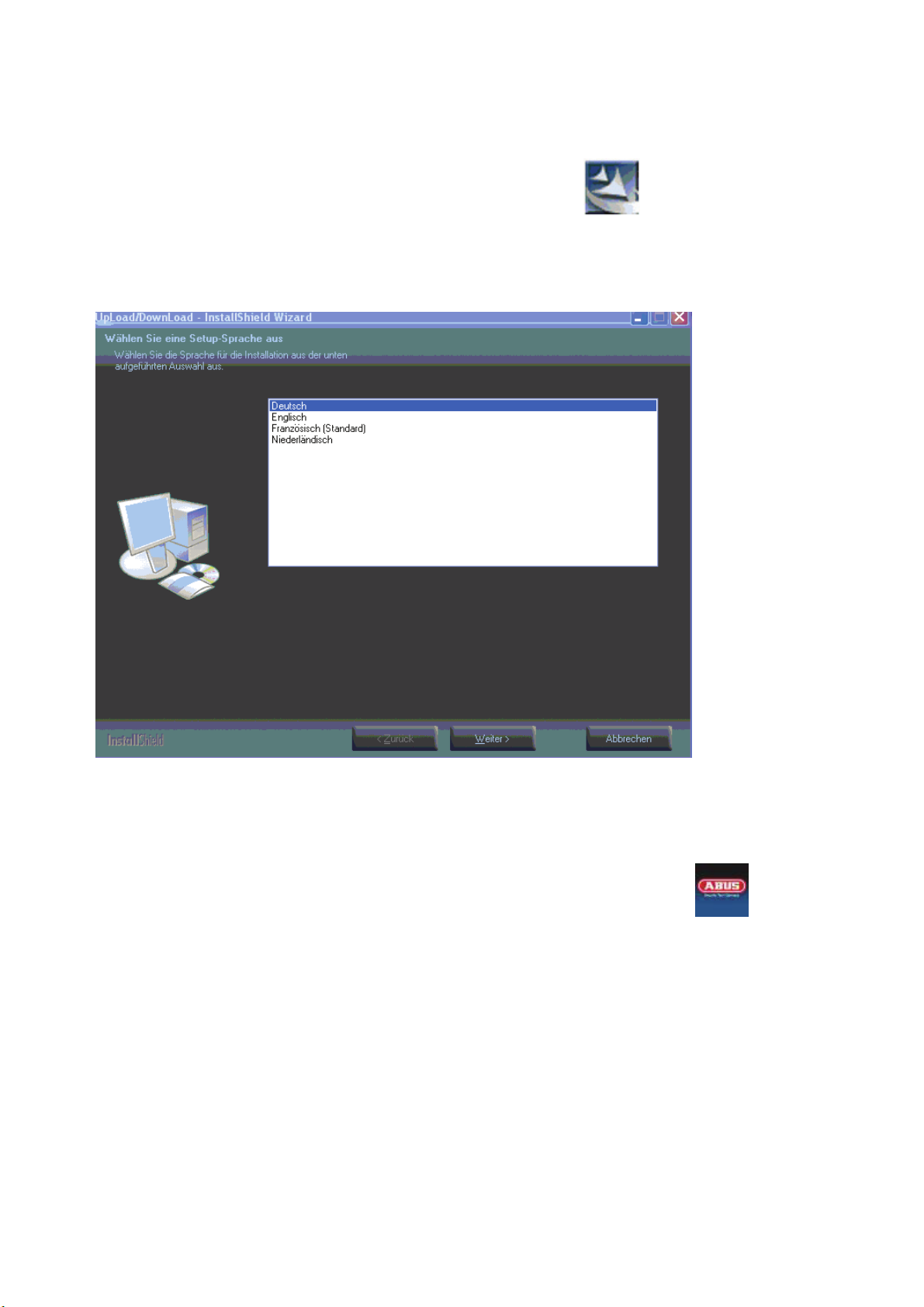
4. The Installation Wizard starts. You are then asked to select a setup language.
5. Select a language and click Next.
6. The installation now takes place in the selected language. Click Next when prompted to do so. Following installation,
reboot your PC.
The software is now installed on your PC and can be used. To start the software, either run the program via the Start menu -> Start-
>All Programs ->ABUS->3.2.1.0->ABUS,
or quite simply double-click the shortcut on your desktop.
2-4
Page 5
Chapter 3 Overview of the software menu options
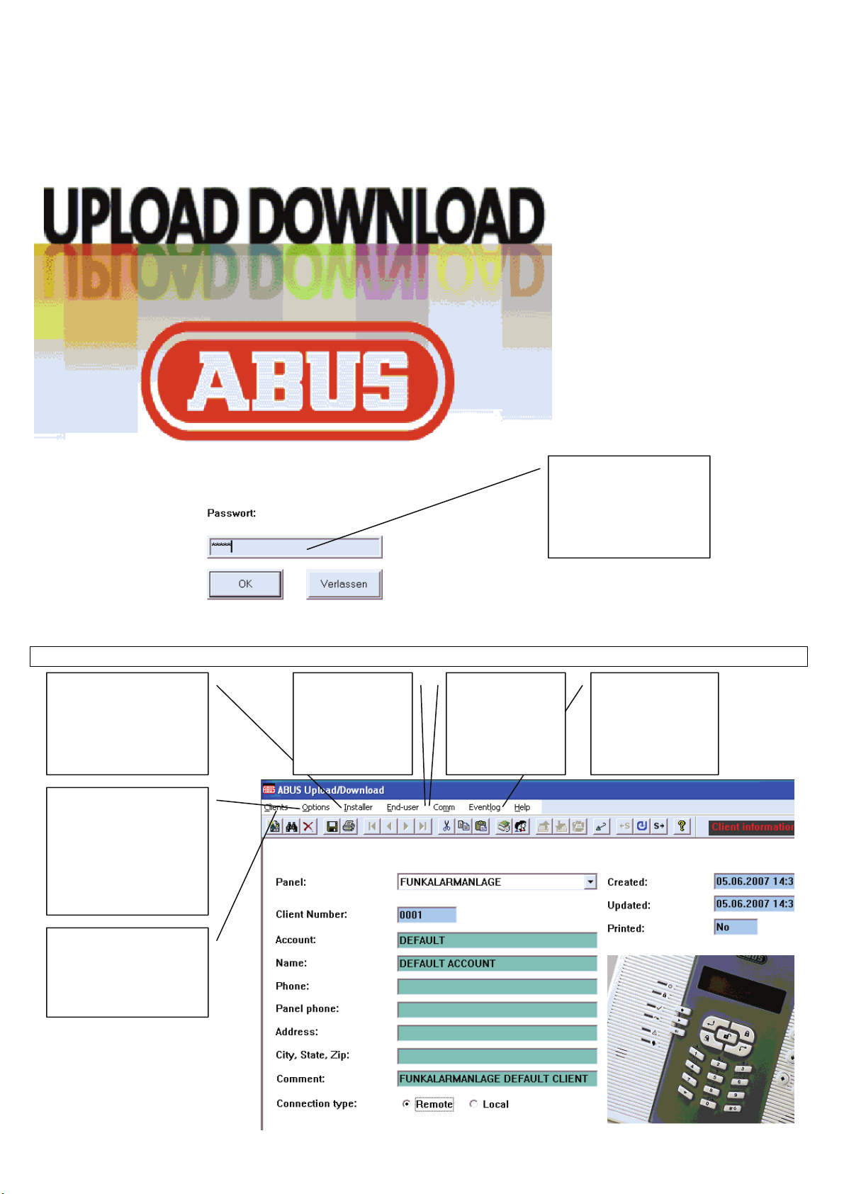
After starting the program, you are asked to enter your password. The factory default of this password is
abus. Enter this password and press OK.
The software starts.
The factory default of this
password is:
abus
3.1
The Upload/Download window
Change settings in the
Installer menu
Change the communication
settings, save and read the
program memory, print
information, and select the
language
Create new clients, search
for clients using search
patterns, and save client
information
Change settings in
the End-user menu
Link to the ABUS
wireless alarm
system to load and
save data
Read and save the
event log
3-5
Page 6

Chapter 4 Creating a new client
To make changes to your ABUS wireless alarm system, you first have to create a new client. Select the Clients dropdown menu. You
can now change the information on the Client information page.
Select New client.
After entering data,
select Save client.
You can now print
the input data under
Print client.
Select Remote for a modem connection.
Select Local for a USB connection.
After creating a new client, you can program it. You can program the client offline (i.e., you are not connected to the client) or online
(i.e., you are connected to the client by a modem or USB.
Enter a serial
number under Client
Number.
Enter a name.
Enter a telephone
number.
Enter a U/D
telephone number.
This number is
dialled if you make a
remote call by
modem.
Enter the city, the
state and the ZIP
code.
Enter a comment.
Chapter 5 Connecting to the client
There are two ways of connecting to the client:
• By modem
• By a direct USB link
Before connecting, make the connection settings. You change these settings in the Options dropdown menu.
Select System
configuration.
Select Remote COM Port
(modem) for a modem
connection. This is usually
port 1. For more
information, see the
Hardware Manager of your
PC.
Select Print options
to change the printer
settings.
Select Interface
Language to
change the software
language.
Select Direct COM Port for a
direct USB connection. This is
usually port 2 or 3. For more
information, see the Hardware
Manager of your PC.
5-6
Page 7

After changing the configuration settings, go to the Client information window and select Loca for a direct USB connection or Remote
for modem connection.
If you select Local, you can start programming the equipment.
If you select Remote, you first have to connect to the client. To do this, select the Comm dropdown menu.
Select Upload all to
transfer data from
the client to the PC.
Select Download all
to transfer data from
the PC to the client.
Select Dial to panel
to establish a remote
connection.
Chapter 6 Panel status
Select End-user -> Status -> Status Display to obtain the following overview of your wireless alarm system.
Under Trouble, you see an
overview of all possible
faults.
Under Zones, you see
an overview of all
zones. Green: not
monitored
Red: monitored
Grey: bypassed
The Accessory field
gives you an overview
of the state of
Select a zone with the
mouse and click this
button to bypass or
include the zone.
Freeze: Freezes the
current screen display.
No sound: Disables sound
signals.
Save: Saves the current
screen.
Press this button to
synchronise the panel
time with the PC system
time.
Select Arm or Disarm to
arm or disarm the system.
A green bar shows that a
connection exists.
A red bar shows that no
connection exists.
connected accessories.
6-7
Page 8

Chapter 7 Installer menu
To program your wireless alarm system, use the Installer dropdown menu. In this menu, you can set the following:
Select System to program system macros and the PIN code.
Select Communication to make settings for alarm calls.
Select Devices to make settings for wireless sounders.
Select Zones to make settings for zones.
Select Utility outputs to make settings for relays.
Select WL button to make settings for remote controls.
Select User codes to define authorities of the user PINs.
Select Follow Me to program alarm events for which the telephone number is to be called.
7.1 System parameters
Under System parameters, you program the system settings. The exact settings are shown in the installation instructions.
Enter the settings accordingly or click the corresponding items. Click a menu option to enable it. Some settings have to be selected
from the dropdown menu. After making all settings, send the data to the client. Click to send the screen data and confirm with Yes.
The data is transferred to the client and the Application succeed dialog box opens. The client emits a brief signal tone.
Confirm the dialog with OK. Make the settings under System und Commuication in the same way.
7-8
Page 9

7.2 Devices
Under Devices, you make the settings for the wireless sounders. Select Installer -> Devices -> Sounder.
Make your settings in the dropdown menu. Click a menu option and then select a setting from the next menu. After making all settings,
Select the siren
type:
External
Internal
None
Select whether the
siren emits an alarm
signal and/or an
acknowledgement.
Select how long
the external siren
emits a visual
alarm.
Select the
strobe
frequency.
Select the
duration of
the visual
acknowledg
ement.
Select whether
the siren emits
a visual
acknowledgem
ent.
send the data to the client. Click
to send the screen data and confirm with Yes.
The data is transferred to the client and the Application succeed dialog box opens. The client emits a brief signal tone.
Confirm the dialog with OK.
7.3
Zone parameters
Under Zone parameters, you make the settings for the zones. Select Installer -> Zones -> Zone parameters.
Enter the zone
label via the
keyboard.
Select the zone
type from the
dropdown
menu.
Enter the
partition (1, 2,
3) via the
keyboard.
Select the zone
sound from the
dropdown menu.
For wired zones,
select the zone
termination and
the response
time.
From the
dropdown menu,
select Force
arming, Confirm
and Supervise.
Make your settings accordingly. Some settings have to be selected from the dropdown menu. After making all settings, send the data
to the client. Click
to send the screen data and confirm with Yes.
The data is transferred to the client and the Application succeed dialog box opens. The client emits a brief signal tone.
Confirm the dialog with OK. Make the settings under Zonenverkn[pfung and Auto Test in the same way.
7-9
Page 10

7.4 Utility outputs
y
y
Under Utility outputs, you make the settings for the switched outputs. Select Installer -> Utility outputs.
Enter the
utility output
label via the
keyboard.
Select the
configuration
(pattern) from
the dropdown
menu.
If an output was
selected as
N/O Pulse,
select the pulse
duration.
If you select the
Zone group, you can
define here whether
one or all zone
events have to be
fulfilled for
activation/deactivatio
n.
Select the group
event:
System
Partition
Zone
Code
Select
the event
in the next
menu.
Assign
the
output to
a key.
Make your settings accordingly. Some settings have to be selected from the dropdown menu. After making all settings, send the data
to the client. Click to send the screen data and confirm with Yes.
The data is transferred to the client and the Application succeed dialog box opens. The client emits a brief signal tone.
Confirm the dialog with OK. Then program the authority levels of the user PINs.
7.5
WL button
Under WL button, you make the settings for 4-channel wireless remote control.Select Installer -> WL button.
On the keyboard,
enter the partition (1,
2, 3) that can be
operated with a
remote control device.
Select the function of
the keys:
Key 1 – arm
Key 2 – disarm
Key 3 – small key
4 – large ke
Ke
Make your settings accordingly. After making all settings, send the data to the client. Click to send the screen data and confirm
with Yes.
The data is transferred to the client and the Application succeed dialog box opens. The client emits a brief signal tone.
Confirm the dialog with OK.
7-10
Page 11

7.6 Follow Me
Under Follow Me, you make the settings for the events that cause an alarm to be transmitted by telephone. You also define the
remote access phone code that has to be entered if you want to access the system from outside by telephone. Select Installer ->
Follow me.
For every phone number, doubleclick Event. A new menu opens.
Select the events for which you
want to be called by phone.
After making your settings, confirm the dialog with OK. You can now make the same settings for resetting events, i.e., if the event is
reset. Another dialog box opens, but not all event resets are available.
Enter the remote access phone
code via the keyboard. This code
has to be entered by telephone to
dial into the system.
For every phone number, doubleclick Event. A new menu opens.
Select the events for whose reset
you want to be called by phone.
Intruder alarm – The call starts when an intruder alarm is triggered.
Fire alarm – The call starts when a fire alarm is triggered.
Emergency.Alarm – The call starts when an emergency alarm is triggered.
Panic alarm – The call starts when a panic alarm is triggered.
General tamper – The call starts when a tamper alarm is triggered.
Remote programming – The call starts if someone attempts to program the alarm system
from outside.
AC off – The call starts if a power failure is registered.
Duress – The call starts if the system is deactivated by a duress code.
Arm (by partition) – The call starts if the system or a partition is activated.
Disarm (by partition) – The call starts if the system or a partition is deactivated.
Bypass – The call starts if at least one zone is bypassed.
Wireless zone lost – The call starts if at least one wireless detector fails.
W. Low battery – The call starts if at least one wireless detector reports
Bell trouble – The call starts if the siren output is faulty.
False codes – The call starts if a bad PIN code is entered 3 times.
Low battery – The call starts if the standby power supply fails.
Wireless receiver jamming – The call starts if the radio traffic fails.
Bus trouble – The call starts if the internal bus fails.
After making all settings, send the data to the client. Click
to send the screen data and confirm with Yes.
The data is transferred to the client and the Application succeed dialog box opens. The client emits a brief signal tone.
Confirm the dialog with OK.
7-11
Page 12

Chapter 8 End-user menu
To program your wireless alarm system, use the End-user dropdown menu. In this menu, you can set the following:
8.1 Scheduling
Under Scheduling, you set the system time and date and the time of the next arming and disarming operations. You can program up
to 16 schedules for arming/disarming the system automatically. You can also program holiday times.
Give the
schedule a
name.
Select Status to display the status of the system.
Select Scheduling to program a schedule for the automatic arming/disarming of the system.
Select User settings to program user PINs, enter Follow Me numbers, and activate voice messages.
Select User operations to arm/disarm partitions, activate utility outputs, override tampering, and test
system components.
Select one of 16 schedules.
Select the function for this schedule.
Arm/Disarm – Arm/disarm the system
Utility outputs – Arm/disarm relays
User limit – Access restriction of user PINs
Select the same/different times for every day.
Select the type of arming: internal/external
Select a partition, a utility
output or the user PIN.
Select two time periods per day. Between the Start and Stop time,
the system is armed, the output is armed, or the user PIN is valid.
Select 00:00 and 00:00 to deactivate the time period.
After making all settings, send the data to the client. Click
to send the screen data and confirm with Yes.
The data is transferred to the client and the Application succeed dialog box opens. The client emits a brief signal tone.
Confirm the dialog with OK.
Program arming times for the holidays in the same way. You can program max. 20 days in this way.
After making all settings, send the data to the client. Click
to send the screen data and confirm with Yes.
The data is transferred to the client and the Application succeed dialog box opens. The client emits a brief signal tone.
Confirm the dialog with OK.
8-12
Page 13

8.2 User settings
Under User settings, you program the user PINs, the Follow Me numbers and the types of messages to be transmitted.
In the dropdown menu, select User PIN.
In the dropdown menu, select Installer to program the Follow Me numbers.
Program the Follow Me numbers. Enter A for a dial pause.
In the dropdown menu, select whether the alarm system can be programmed via this Follow Me number.
In the dropdown menu, select whether you can listen in to the alarm system via this Follow Me number.
After making all settings, send the data to the client. Click to send the screen data and confirm with Yes.
The data is transferred to the client and the Application succeed dialog box opens. The client emits a brief signal
tone.
Confirm the dialog with OK.
In the dropdown menu, select voice messages to program the messages that cause alarm transmission.
Select the appropriate message
structure from the dropdown
menu.
Enter the user’s first and last name and a four-digit
user PIN.
You cannot make any changes to the authority level
and the partition authority.
After making all settings, send the data to the
client. Click to send the screen data and
confirm with Yes.
The data is transferred to the client and the
Application succeed dialog box opens. The
client emits a brief signal tone.
Confirm the dialog with OK.
Select whether the corresponding
action causes alarm
transmission.
After making all settings, send the
data to the client. Click
the screen data and confirm with
Yes.
The data is transferred to the client
and the Application succeed
dialog box opens. The client emits
a brief signal tone.
to send
8-13
Page 14

8.3 User operations
Under User operations, you can perform system functions such as arming and disarming partitions, controlling utility outputs, etc. You
can also test partitions.
Select functions and confirm the dialog.
Chapter 9 Comm
Under Comm, you can upload screen data or all data, and send screen data or all data to the client. You also use this dropdown menu
for calling the system via a modem (remote) connection.
Upload screen – Select to upload data from the client.
Upload screen – Select to upload data from the client.
Upload screen – Select to upload data to the client.
Upload all – Select to upload all data to the client.
Verify screen – Select to compare screen data with
client data.
Wait for call – Select to program the software so that it waits for an incoming call from the
system.
Dial to panel – Select to call the number saved under U/D number.
Hand over – Select to hand over a call.
Hang up – Select to terminate a call.
Message to LCD Keypad – Select to send a text message to the LCD display of the
system.
Chapter 10 Eventlog
Under Eventlog, you can read the system event log.
Upload all – Select to read all system data saved so that you can view it later under View. The data
Upload recent – Select to read the latest system events. The data is saved in an event log.
View – Select to view the events downloaded from the system.
View from file – Select to view a saved file of an event log.
is saved in an event log.
10-14
 Loading...