

Page 1
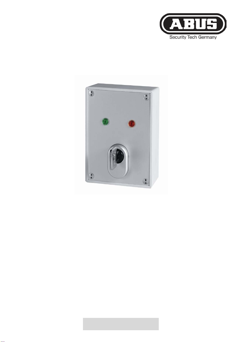
Privest Funk-Schlüsselschalter
Installations- und Bedienungsanleitung (DE)
Wireless key switch
Installation and operating instructions (UK) ......................... 6
Interrupteur à clé
Instructions d’installation et de commande (FR) ................ 11
Interruttore a chiave via radio
Istruzioni di installazione e per l'uso (IT) ............................ 16
Draadloze sleutelschakelaar
Installatie- en bedieningshandleiding (NL) ......................... 20
Trådløs nøglekontakt
Installations- og betjeningsvejledning (DK) ........................ 25
13022012
FU9075
Page 2

Vorwort
Sehr geehrte Kundin, sehr geehrter Kund e,
wir bedanken uns für den Kauf dieses Funk-Schlüsselschalters. Dieses
Produkt ist nach dem heutigen Stand der Technik gebaut. Es erfüllt die
Anforderungen der geltenden europäischen und nationalen Richtlinien. Die
Konformität wurde nachgewiesen, die entsprechenden Erklärungen und
Unterlagen sind beim Hersteller (www.abus-sc.com) hinterlegt. Um
gefahrlosen Betrieb s ich erzustellen, müss en Sie als A n wender d iese Anleitung
beachten! Bei Fragen wenden Sie sich bitte an Ihren Fachhändler. Das
gesamte Produkt darf nicht geändert und umgebaut werden.
Diese Anleitung enthält wichtige Hinweise zur Inbetriebnahme und
Handhabung. Heben Sie d iese Bedienungsanleitung desha lb zum Nachlesen
auf! Diese Anleitung gehör t zu diesem Produkt. Achten Sie darauf wenn Sie
dieses Produkt an Dritte weitergeben.
Haftungsausschluss:
Diese Bedienungsanleitung wurde mit größter Sorgfalt erstellt. Sollten Ihnen
dennoch Auslassungen oder Ungenauigkeiten auffallen, so teilen Sie uns
diese bitte an die angegebene Adresse mit.
Die ABUS Secur ity-Center GmbH übernimm t keinerlei Haftung für technische
und typographische Fehler und behält sich das Recht vor, jederzeit ohne
vorherige Ankündigung Änderungen am Produkt und an den
Bedienungsanleitun gen vor zun ehmen.
Der Inhalt dieser Anleitung kann ohne vorherige Bekanntgabe geändert
werden. Es wird keinerlei Garantie für den Inhalt dieses Dokuments
übernommen.
© ABUS Security-Center GmbH & Co. KG, 02 / 2012
2
Page 3

Hinweise
Der Funk-Schlüsselschalter dient im Zusammenhang mit der ABUS
Funkalarmanlage zum Aktivieren, bzw. D eaktivieren des Systems oder dessen
Teilbereiche.
Durch den Deckel- und Wandabrisskontak t, sowie der Kernziehschutzrosette
und dem hochwertigen Zylinder aus dem Hause ABUS ist der
Schlüsselschalter in erhöhtem Maße gegen Angriffe von außen geschützt.
Hauptmerkmale
• Aufputz Funk-Schlüsselschalter
• Stabiles wetterfestes Gehäuse
• Kernziehschutzrosette
• Deckel- und Wandabrisskontakt
• Farbige LED Status-Anzeige
Lieferumfang
4 Gehäusespezialschrauben inkl. Stiftschlüssel
1 Runddichtung
4 Mauerdübel inkl. Schrauben
Konformität
Die Konformitätserk lärung is t zu beziehen unter :
ABUS Security-Center GmbH & Co. KG
Linker Kreuthweg 5
86444 Affing
GERMANY
www.abus-sc.com
info@abus-sc.com
3
Page 4
4
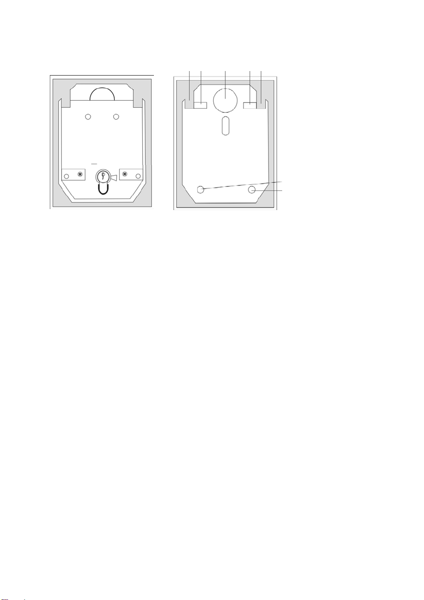
Beschreibung
1 2 2 1
1
Platinenhalter
2 Wandbefestigung
2
2
[Abb.1]
(mit Platine
Montage
Gehäuse
offen
)
[Abb.2]
Gehäuse ohne
Platine
1. Öffnen Sie mit dem beiliegenden Stiftschlüssel die Deckelschrauben
und nehmen Sie den Gehäusedeckel ab.
2. Entfernen Sie die beiden Plat inens c hrauben links und rechts vom
Zylinder.
3. Ziehen Sie die Platine am Zylinder vorsichtig nach oben heraus.
4. Benutzen Sie die Rückseiten des Schlüsselschaltergehäuses zum
Markieren der Befestigungen (2). Bohren Sie dann die Haltelöcher.
5. Befestigen Sie den Funkschlüsselschalter mit Hilfe der beiliegenden
Schrauben an der Wand.
6. Setzen Sie die Platine wieder ein. Achten Sie dabei darauf, dass der
Wandabrisskontakt eingedrückt wird.
7. Schließen Sie die beiliegende Batterie an.
8. Setzen Sie den Deck el wieder auf und verschrauben Sie diesen
anschließend mit den vier Spezialschrauben.
Page 5

Abmessungen Aufbau
85 x 114 x 42mm (BxHxT)
Schutzart
IP55
Gewicht
450g
Frequenz
868,65MHz
HF-Immunität
20V/m 80MHz-1GHz
Modulation
AM
Supervision
Keine
Batterie
3,6V DC, Li-Batterie Typ AA
Batterielebensdauer
Ca. 1 Jahr
Betriebstemperatur
-10°C bis 50°C
5
Einlernen des Funkschlüsselschalters
1. Die ABUS Alarmanlage muss sich im Programmiermodus
befinden.
2. Im Menüpunkt „Zonen“ wählen Sie den Menüpunkt
„Zuordnung“ und setzen Sie Ihre Anlage in den Einlernmodus.
Der Schriftzug „Warte auf Signal“ erscheint im Display.
3. Stecken Sie den Schlüssel in den Zylinder und drehen Sie ihn
bis zum Anschlag im Uhrzeigersinn, so dass die rote LED
aufleuchtet. Halten Sie den Zylinder in dieser Position.
4. Nach ca. drei Sek unden blinkt die ro te LED im Wechsel mit der
grünen und der Sender sendet die Einlernnachricht.
5. Vergewissern Sie sich an der Anlage, dass diese den Melder
erkannt hat.
6. Programmieren Sie für diesen Melder keine
Supervision.
7. Die Zone ist als Zonentyp „Blockschloss verzögert“ zu
programmiert, so startet die Anlage nach dem Aktivieren die
Ausgangsverzögerungszeit.
8. Setzen Sie Ihre Alarmanlage wieder in den normalen
Betriebsmodus zurück .
Technische Daten
Der Hersteller behält sich vor technische Änderungen ohne
Vorankündigung durch zuf ühren.
Page 6

FU9075
Privest Wireless key switch
Installation and operating instructions (UK)
13022012
Wireless key switch
Installation and operating instructions (UK) ......................... 6
Interrupteur à clé
Instructions d’installation et de commande (FR) ................ 11
Interruttore a chiave via radio
Istruzioni di installazione e per l'uso (IT) ............................ 16
Draadloze sleutelschakelaar
Installatie- en bedieningshandleiding (NL) ......................... 20
Trådløs nøglekontakt
Installations- og betjeningsvejledning (DK) ........................ 25
Page 7

Preface
Dear customer,
Many thanks for your purchase of this Wireless key switch. This product is built
according to state-of-the-art technology. It com plies with current dom estic and
European regulations. Conformity has been proven, and all related
certifications are available from the manufacturer on request (www.abussc.com). To ensure safe operation, it is your obligation to observe these
instructions! If you have any questions, please contact your local specialist
dealer. No part of the product may be changed or modified in any way.
These instructions contain important installation and operation information.
Store these instruct ions in a saf e place f or f uture ref erenc e. Thes e inst ructio ns
are part of the product. Bear this in mind if you pass the product on to others.
Disclaimer:
These operating instructions have been produced with the greatest care.
Should you discover any missing information or inaccuracies, please contact
us under the address shown.
ABUS Security-Center GmbH does not accept any liability for technical and
typographical errors, and reserves the right to m ake changes to the product
and operating instructions at any time and without prior warning.
We reserve the right to make changes to these instructions without prior
notice. No forms of guarantee are accepted for the contents of this document.
© ABUS Security-Center GmbH & Co. KG, 02 / 2012
7
Page 8

8
Notes
The radio key switch is us ed for activat ing/deactivat ing the ABUS r adio alarm
system or its partitions.
It is well protected ag ainst external interference, than ks to the cover contact
and the anti-removal wa ll c ontac t, as well as t he reinforced fasc ia pl ate, whic h
prevents removal of the high-quality ABUS cylinder.
Main features
• Surface-mounted key switch
• Stable, weatherproof casing
• Reinforced fascia plate to prevent lock removal
• Anti-removal wall and ceiling contact
• Colored LEDs
• Modern, attractive design
Scope of delivery
4 special casing screws with key
1 circular seal
4 wall plugs with sc rews
Conformity
The declaration of conformity can be ordered from:
ABUS Security-Center GmbH & Co. KG
Linker Kreuthweg 5
86444 Affing
GERMANY
www.abus-sc.com
info@abus-sc.com
Page 9

9
Description
1 2 2 1
1
PCB
2 Wall fixing
2
2
[Fig. 1]
Casing
open
PCB)
(with
[Fig. 2]
Casing without
PCB
Installation
1. Using the key supplied, unscrew the cover screws and remove
the cover plate.
2. Remove the two PCB screws on the left and right of the cylinder.
3. Pull the cylinder and PCB carefully upwards and out.
4. Use the back of the key-switch case as a template for marking
the drill holes (2). Drill the holes for the fixing screws.
5. Fix the key switch to the wall using the screws supplied.
6. Replace the PC board. Mak e sure that the anti-removal tamper
contact is pressed.
7. Connect the battery supplied.
8. Replace the cover and screw it tight with the four special screws.
holder
Page 10

Dimensions (surface fitting)
85 x 114 x 42mm (WxHxD)
Protection type
IP55
Weight
450g
Frequency
868.65 MHz
HF immunity
20V/m 80MHz–1GHz
Modulation
AM
Supervision
None
Battery
3.6V DC, Li battery type AA
Battery lifetime
Ca. 1 year
Ambient operating temperature
-10°C – 50°C
10
Training the key switch
1. The ABUS alarm system must be in programming mode.
2. Under “Zones”, select “Allocation” and set the system to
learn mode. You see the message “(Re) Write” on the display.
3. Insert the key in the cylinder and turn it clockwise to its end
stop so that the red LED lights up. Keep the key in this
position.
4. After about 3 seconds, the red and green LED flash
alternately and the transmitter sends the learn message.
5. Check that the alarm system has recognised the detector.
6. Program no
supervision for this detector.
7. Program the zone as “Latch KSW” zone type. If you
program the zone as “BlLatch KSW delay”, the system
starts the exit delay time following activation.
8. Switch the alarm centre back to normal operating mode.
Technical data
The manufacturer reserves the right to make technical
modifications without prior notice.
Page 11

Privest Interrupteur à clé
Instructions d’installation et de commande (FR)
Wireless key switch
Installation and operating instructions (UK) ......................... 6
Interrupteur à clé
Instructions d’installation et de commande (FR) ................ 11
Interruttore a chiave via radio
Istruzioni di installazione e per l'uso (IT) ............................ 16
Draadloze sleutelschakelaar
Installatie- en bedieningshandleiding (NL) ......................... 20
Trådløs nøglekontakt
Installations- og betjeningsvejledning (DK) ........................ 25
13022012
FU9075
Page 12

12
1. Préface
Chère cliente, cher client,
Nous vous rem ercions d’avoir opté pour l’Interrupt eur á clè. Le présen t produit
fait appel à une technologie de pointe. Il est conforme aux exigences des
directives europé ennes et natio nales en vigueur. La conformité de ce pro duit a
été prouvée. L es déclarations et documents c orrespondants s ont consultab les
auprès du fabricant (www.abus-sc.com). Pour qu’un fonctionnement en toute
sécurité puiss e être assur é, lire attent ivement la pr ésente notice. Pour plus de
renseignements, adressez-vous à votre vendeur spécialiste sur place. Une
modification ou transformation de la structure d’une quelconque partie de ce
produit n’est pas autorisée.
Cette notice comporte des consignes importantes de mise en service et de
manipulation. Conser vez donc les présentes instructi ons de service, afin de
pouvoir les consulter ! Les présentes instructions font partie intégrante du
produit. Ne les oubliez pas lors de la remise du produit à un tiers.
Clause de non-responsabilité :
Le présent mode d’emploi a été élaboré avec le plus grand soin. Si vous
veniez cependant à remarquer des omissions ou autres imprécisions, nous
vous prions de bien vouloir nous les signaler en les faisant parvenir à
l’adresse indiquée.
La société ABUS Securit y-Center GmbH décline toute responsabil ité en cas
d’erreurs techniques ou typographiques et se réserve le droit de modifier à
tout moment le produit et les modes d’emploi sans préavis.
Sous réserve d’u ne modification du contenu du présent doc ument sans avis
préalable. Le contenu de ce document ne fait l’objet d’aucune garantie.
© ABUS Security-Center GmbH & Co. KG, 02 / 2012
Page 13

13
Remarques
Conjointement au système d’alarme sans fil ABUS, le présent interrupteur à
clé amovible sans fil permet d’activer ou de désactiver le système et ses
secteurs.
De par le contact du couvercle et anti-arrachement mural ainsi que la
rosette de protection du cylindre et le cylindre de qualité de la société
ABUS, cet interrupteur à clé amovible dispose d’une protection forte contre
les agressions venant de l’extérieur.
Principales caractéristiques
• Interrupteur à clé am o vib le sans fil pour montage apparent
• Boîtier stable résistant aux intempéries
• Rosette de protection du cylindre
• Contact de couvercle et anti-arrachement mural
• Affichage à DEL couleur
• Design modern agréable
Livraison
4 vis de boîtier spéciales et clé mâle coudée
1 joint rond
4 chevilles de fixation murale avec vis
Conformité
La déclaration de conformité est disponible auprès de :
ABUS Security-Center GmbH & Co. KG
Linker Kreuthweg 5
86444 Affing
GERMANY
www.abus-sc.com
info@abus-sc.com
 Loading...