

Page 1

1
BOM-No. 12244842
FU8200
Funk-Infomodul
Installationsanleitung
Page 2

2
Funk-Infomodul
Installationsanleitung (DE) ............................ 1
Wireless info module
Installation instructions (UK) ....................... 23
Module d’information sans fil
Instructions d’installation (FR) ..................... 45
Modulo radio info
Istruzioni per l’installazione (IT) .................. 67
Draadloze infomodule
Installatiehandleiding (NL) .......................... 89
Trådløst infomodul
Installationsvejledning (DK) ...................... 111
Radiowy moduł informacyjny
Instrukcja instalacji (PL) 133
Page 3

3
0. Vorwort
Sehr geehrte Kundin, sehr geehrter Kunde,
wir bedanken uns für den Kauf dieses Funk-Infomoduls
für Ihre Secvest Funkalarmzentrale. Dieses Produkt ist
nach dem heutigen Stand der Technik gebaut. Es erfüllt
die Anforderungen der geltenden europäischen und
nationalen Richtlinien. Die Konformität wurde
nachgewiesen, die entsprechenden Erklärungen und
Unterlagen sind beim Hersteller (www.abus-sc.eu)
hinterlegt. Um diesen Zustand zu erhalten und einen
gefahrlosen Betrieb sicherzustellen, müssen Sie als
Anwender diese Anleitung beachten! Bei Fragen wenden
Sie sich bitte an Ihren Fachhändler. Das gesamte
Produkt darf nicht geändert und umgebaut werden.
Diese Anleitung enthält wichtige Hinweise zur
Inbetriebnahme und Handhabung. Heben Sie deshalb
diese Bedienungsanleitung zum Nachlesen auf! Diese
Anleitung gehört zu diesem Produkt. Achten Sie darauf
wenn Sie dieses Produkt an Dritte weitergeben.
Page 4

4
Es wurde alles Erdenkliche unternommen, um
sicherzustellen, dass der Inhalt dieser Anleitung korrekt
ist. Jedoch kann weder der Verfasser noch die ABUS
Security-Center GmbH & Co. KG die Haftung für einen
Verlust oder Schaden übernehmen, der mittelbar oder
unmittelbar aufgrund dieser Anleitung verursacht wurde,
oder von dem behauptet wird, dass er dadurch
entstanden ist. Der Inhalt dieser Anleitung kann ohne
vorherige Bekanntgabe geändert werden.
© ABUS Security-Center GmbH & Co. KG, August 2012
Page 5

5
1. Bestimmungsgemäße Verwendung
Dieses Funkinfomodul zeigt den Status des
ausgewählten Teilbereiches an. Es dient zur akustischen
Reproduktion der Infotöne und Alarmtöne Ihrer
Funkalarmzentrale.
Der eingebaute Piezosignalgeber dient außerdem als
interne Sirene während eines Alarms.
Es wird hauptsächlich an Nebeneingangstüren oder
Garagentüren, sowie an allen anderen möglichen
Zugangsbereichen eingesetzt.
Der Kontakt des Gerätes nebst angeschlossenen
Komponenten mit Feuchtigkeit, z.B. im Badezimmer u.ä.
ist unbedingt zu vermeiden.
Eine andere Verwendung als die zuvor beschriebene
kann zur Beschädigung dieses Produkts führen. Das
Produkt wird mit einem Steckernetzteil oder
Unterputznetzteil mit 12VDC / ≥600mA betrieben. Das
gesamte Produkt darf nicht geändert bzw. umgebaut
werden.
Page 6

6
2. Inhalt
0. Vorwort ......................................................................... 3
1. Bestimmungsgemäße Verwendung ............................ 5
2. Inhalt ............................................................................ 6
3. Sicherheitshinweise ..................................................... 7
4. Lieferumfang ................................................................ 8
5. Anzeigen und Bedienelement ...................................... 8
6. Akustische Signaltöne ............................................... 11
7. Installation .................................................................. 13
7.1. Standortprüfung .................................................. 13
7.2. Öffnen des Gehäuses ........................................ 14
7.3. Anbringen der Rückwand ................................... 16
7.4. Zuweisung der Secvest zum Infomodul ............. 16
7.5. Beendigung der Installation ................................ 18
8. Test der Signalstärke ................................................. 19
8.1. Durchführung eines Signalstärkentests ............. 19
9. Technische Daten ...................................................... 20
Page 7

7
3. Sicherheitshinweise
!Vorsicht!
Durch unsachgemäße oder unsaubere
Installationsarbeiten kann es zu Fehlinterpretationen von
Signalen kommen. Die Folgen können beispielsweise
Fehlalarme sein. Die Kosten für mögliche Einsätze von
Rettungskräften, wie z.B.: Feuerwehr oder Polizei, sind
vom Betreiber der Anlage zu tragen.
Das Gerät wurde nur für die Innenanwendung gebaut.
Beachten Sie die Anweisungen und Hinweise in dieser
Anleitung! Sollten Sie sich nicht an diese Anleitung halten
erlischt Ihr Garantieanspruch! Eine andere Verwendung
als die Beschriebene kann zur Beschädigung dieses
Produkts führen. Der elektronische Teil des Produkts darf
nicht geändert oder umgebaut werden. Für
Folgeschäden wird keine Haftung übernommen!
Page 8

8
4. Lieferumfang
Funk-Infomodul
3 Mauerdübel 8x36mm
3 Schrauben 3x33mm
Mehrsprachige Anleitung
5. Anzeigen und Bedienelement
Das Infomodul hat 8 untereinander angeordnete LEDs,
die folgende Informationen anzeigen:
LED Spannung (grün)
leuchtet permanent, wenn Spannung vorhanden ist
LED Empfang (grün)
blinkt jedes Mal, wenn das Infomodul ein gültiges Signal
empfängt
Page 9
9
LED Aktiviert (rot)
leuchtet, wenn der eingestellte Teilbereich aktiviert ist
LED Warnung (gelb)
leuchtet, wenn eine Rückstellung der Funkalarmzentrale
erforderlich ist oder die Funkalarmzentrale Informationen
zum Anzeigen hat.
LED Intern Aktiviert (gelb)
leuchtet, wenn der eingestellte Teilbereich intern aktiviert
ist
Page 10
10
LED Bereit (rot)
leuchtet, wenn mindestens eine Zone des eingestellten
Teilbereichs geöffnet ist oder wenn sich die Zentrale im
Errichtermodus befindet.
(Der Menüpunkt an der Funkalarmzentrale:
ERRICHTERMODUS And. Komponenten
Infomodul/Int. Sirene Bereit LED“ muss dazu auf
„Aktiviert“ gesetzt sein.)
LED Verzögerungszeit (gelb)
leuchtet, wenn die Aus-/Eingangsverzögerung läuft
LED Alarm (rot)
leuchtet, wenn ein Alarm ausgelöst wurde. Außerdem
ertönt der interne Piezosignalgeber.
Page 11

11
Unten rechts am Gehäuse befindet sich ein kleines Loch,
das einen Zugang zu einem internen Schalter ermöglicht,
der zur Überwachung der Signalstärke verwendet wird.
6. Akustische Signaltöne
Das Infomodul ist in der Lage, eine ganze Reihe von
akustischen Signaltönen zu erzeugen. Diese sind ähnlich
den Signaltönen der Funkalarmzentrale. Zugleich wird
bei Alarm der interne Piezosignalgeber des
Funkinfomoduls aktiviert und dient so als zusätzliche
Innensirene.
Die folgende Tabelle zeigt eine Übersicht über die
Signaltöne und Ihre Bedeutung.
Page 12
12
Signalton
Bedeutung
Kurzer Piepton
(beep)
Störung an der Anlage, die Zentrale
kann nicht aktiviert werden.
Unterbrochene
Pieptöne
(beep…beep…beep)
Eine Zone wurde während der
Ausgangsverzögerungszeit
geöffnet. Sie muss vor Ablauf der
Verzögerungszeit geschlossen
werden.
Langer
durchgehender
Piepton
(beeeeeeeeeeeep)
Während der
Ausgangsverzögerungszeit. Alle
Zonen geschlossen, Zentrale wird
nach Ablauf der Verzögerungszeit
aktiviert.
Kurze unterbrochene
Pieptöne
(beepbeepbeepbeep)
Während der
Eingangsverzögerungszeit.
Unterschiedlich hoher
Piepton
Zentrale wurde erfolgreich
aktiviert.
Einlernsignal empfangen und
gespeichert.
Beim Verlassen des
Errichtermodus.
Türgong (wenn bei
Zoneneigenschaften
ausgewählt).
Page 13

13
7. Installation
Sie sollten das Modul flach an der Wand auf einer
praktischen Höhe für den Bediener montieren. Achten
Sie darauf, dass eine geeignete Gleichstromversorgung
mit 12 V vorhanden ist. Sie können das Infomodul bis zu
100 m von Ihrer Funkalarmzentrale anbringen. Die
Empfangsreichweite ist stark von den baulichen
Gegebenheiten des Gebäudes abhängig.
7.1. Standortprüfung
Sie sollten die Stärke des eingehenden Signals an der
geplanten Position für das Infomodul messen. Sie
können dazu die Funktestbox FU3801 aus unserem
Hause für diesen Zweck einsetzen. Wenn Sie keine
Funktestbox besitzen, können Sie das Infomodul selbst
zur Anzeige der Signalstärke verwenden (siehe Kap.
Test der Signalstärke).
Vermeiden Sie folgende Montageorte:
In der Nähe von oder an großen Metallkonstruktionen.
Weniger als 1 Meter entfernt von Stromleitungen und von
Metall-, Wasser- und Gasrohren. Innerhalb von
Stahlgehäusen. Neben Elektrogeräten, insbesondere
Computer, Fotokopierer oder Kommunikationsgeräten.
Page 14
14
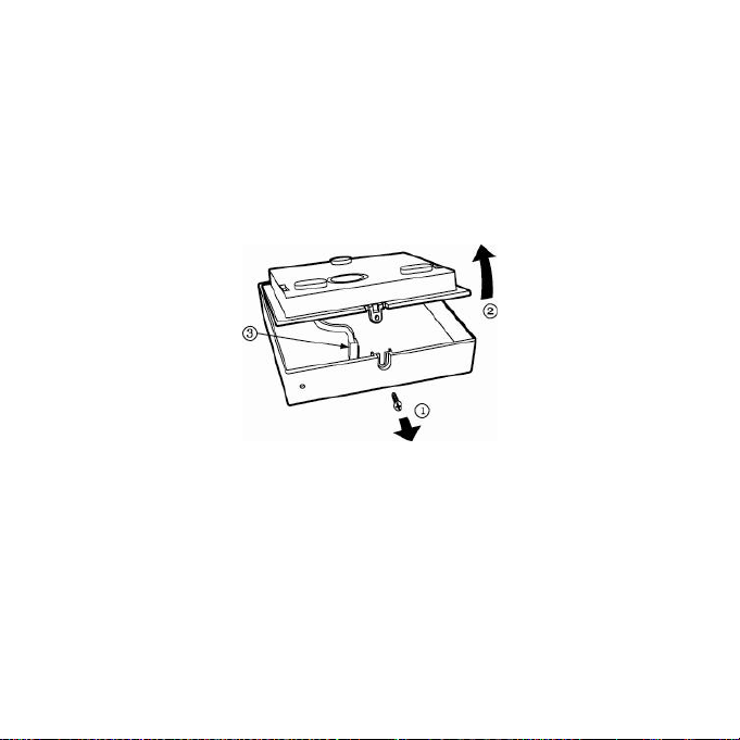
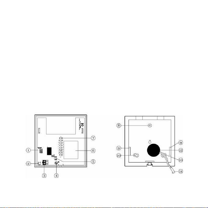
7.2. Öffnen des Gehäuses
Um einen Zugang zur Rückwand zu erhalten, lockern Sie
die Schraube unten am Gehäuse (1) und bewegen das
Vorderteil behutsam ein Stück nach oben (2). Trennen
Sie das Kabel vom Piezosignalgeber zur Leiterplatte (3),
bevor Sie die Rückwand vollständig entfernen.
Abb. 1: Öffnen des Gehäuses
Page 15
15
1. Steckbrückenanschlüsse zur Auswahl des
Teilbereichs
2. Taste zum Anzeigen der Signalstärke
3. Schraubklemmleiste für 12 Volt Anschluss
4. Potentiometer
5. Steckverbinder für internen Piezosignalgeber
6. Funkempfangsmodul
7. LEDs
8. Oberes Befestigungsloch
9. Kabeleinführungsöffnungen
10. Befestigungslöcher
11. Verbindungskabel zum Piezosignalgeber
12. Piezosignalgeber
Abb. 2: Innenansicht
Page 16

16
7.3. Anbringen der Rückwand
1. Nutzen Sie die Bodenplatte als Bohrschablone
und zeichnen Sie die Löcher an die Wand.
Bohren Sie die Löcher und setzen Sie bei Bedarf
Dübel ein.
2. Führen Sie das Anschlusskabel des Netzteils in
das Gerät ein und schrauben Sie die Rückseite
des Gehäuses an die Wand.
7.4. Zuweisung der Secvest zum Infomodul
1. Am Infomodul stellen Sie zuerst sicher, dass
keine Steckbrücke gesteckt ist. Dann versorgen
Sie das Infomodul mit Spannung (die Polarität
der Klemmleiste ist auf der Leiterplatte
aufgedruckt). Die untersten sieben LEDs blinken.
Damit ist der Lernmodus aktiviert.
2. Wählen Sie im Errichtermodus der
Funkalarmzentrale den Menüpunkt „And.
Komponenten Infomodul/Int. Sirene
Komponente einlernen“
Page 17

17
3. Drücken Sie an der Funkalarmzentrale „Send“
Die Zentrale sendet das Einlernsignal zum
Infomodul.
Wenn das Einlernen der Funkalarmzentrale
erfolgreich war:
Hören die untersten sieben LEDs des
Infomoduls auf zu blinken.
Leuchten alle LEDs dauerhaft.
Gibt das Infomodul einen Doppelton aus.
4. Bestätigen Sie den erfolgreichen Einlernvorgang
an der Funkalarmzentrale.
5. Legen Sie nun fest, über welchen Teilbereich das
Infomodul informieren soll. Wählen Sie mit Hilfe
der Steckbrücke den Teilbereich aus.
Haben Sie einen Teilbereich gewählt, gibt das
Infomodul erneut einen Doppelton aus. Nur die
grüne LED für die Spannung leuchtet noch.
Das Infomodul hat den Lernmodus verlassen.
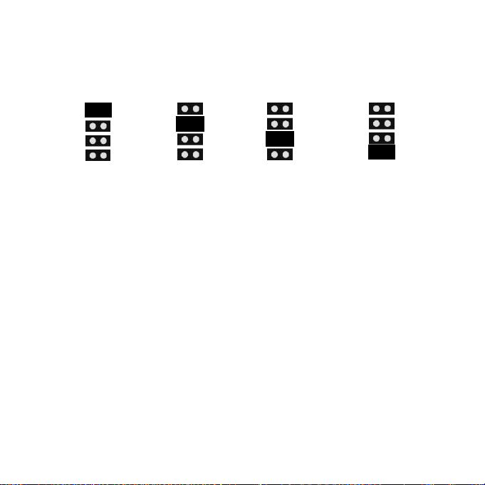
Die Grafik zeigt die Steckbelegung für die
verschiedenen Teilbereiche:
Page 18
18
Teilbereich 1 Teilbereich 2 Teilbereich 3 Teilbereich 4
7.5. Beendigung der Installation
Wenn Sie keine Funk-Standortprüfung durchgeführt
haben, müssen Sie unbedingt die Stärke des
eingegangenen Signals prüfen (siehe Kap. Test der
Signalstärke)
Wenn Sie mit der Signalstärke zufrieden sind:
1. Schließen Sie das Kabel vom Piezosignalgeber
wieder an der Leiterplatte an.
2. Bringen Sie das Vorderteil an der Rückwand des
Gehäuses an und befestigen Sie es mit der
Schraube (führen Sie die Anweisungen in
Abbildung 1 in umgekehrter Reihenfolge durch).
Page 19

19
8. Test der Signalstärke
Das Infomodul ist in der Lage, die Signalstärke der
empfangenen Signale von der Zentrale anzuzeigen.
Hinweis:
Achten Sie darauf, dass die Zentrale in das Infomodul
eingelernt ist.
Stellen Sie sicher, dass eine Steckbrücke für die Auswahl
des Teilbereichs gesteckt ist.
8.1. Durchführung eines Signalstärkentests
Sobald das Infomodul ein Signal von der
Funkalarmzentrale erhalten hat, betätigen Sie am
Infomodul den Taster zum Anzeigen der Signalstärke
(verwenden Sie dazu ein langes spitzes Werkzeug, das
Sie durch das Loch unten am Gehäuse führen können).
Die LEDs zeigen die Stärke des empfangenen Signals
an. Je mehr LEDs erleuchtet sind (von unten nach oben),
desto stärker ist das Signal. Wenn nur zwei LEDs oder
Page 20

20
weniger erleuchtet sind, ist das Signal nicht stark genug
Umweltklasse
II
Sicherheitsgrad
2 EN50131-1 und -3
Schutzklasse
IP 54
Betriebstemperatur
-10°C bis +55°C
Luftfeuchtigkeit
96% Relative Luftfeuchtigkeit
Abmessungen
123,9 x 123,9 x 40,7mm
(BxHxT)
Gewicht
200g
Spannungsversorgung
9-14V DC, 12V DC nominal
Stromaufnahme
55±5% mA (Stand-by)
600mA Alarmzustand
Frequenz
868,6625 MHz
Anzeige
8 verschiedenfarbige LEDs
Signale
Interner Piezo
max.110dB(A)@1m
Sabotageüberwacht
nein
für einen zuverlässigen Betrieb. Die grüne LED für die
Spannung leuchtet immer.
9. Technische Daten
Irrtümer und technische Änderungen vorbehalten.
Page 21

21
Dieses Gerät erfüllt die Anforderungen der EU-Richtlinie
1999/5/EG des Europäischen Parlaments und des Rates
vom 9. März 1999 über Funkanlagen und
Telekommunikationsendeinrichtungen und die
gegenseitige Anerkennung ihrer Konformität.
Die Konformitätserklärung ist zu beziehen unter:
ABUS Security-Center GmbH & Co. KG
Linker Kreuthweg 5
D 86444 Affing
Germany
www.abus-sc.eu
info@abus-sc.eu
Page 22

22
Page 23
23
BOM-No. 12244842
FU8200
Wireless info module
Installation Instructions
Page 24

24
Funk-Infomodul
Installationsanleitung (DE) ............................ 1
Wireless info module
Installation instructions (UK) ....................... 23
Module d’information sans fil
Instructions d’installation (FR) ..................... 45
Modulo radio info
Istruzioni per l’installazione (IT) .................. 67
Draadloze infomodule
Installatiehandleiding (NL) .......................... 89
Trådløst infomodul
Installationsvejledning (DK) ...................... 111
Radiowy moduł informacyjny
Instrukcja instalacji (PL) 133
Page 25

25
0. Preface
Dear customers,
Many thanks for your purchase of this wireless info
module for your Secvest wireless alarm centre. This
product is built according to state-of-the-art technology. It
complies with current domestic and European
regulations. Conformity has been proven, and all related
certifications are available from the manufacturer on
request (www.abus-sc.eu). To maintain this status and to
guarantee safe operation, it is your obligation to observe
these instructions. In the event of questions, please
contact your local specialist dealer. No part of the product
may be changed or modified in any way.
This manual contains important installation and operation
instructions. Store these instructions in a safe place for
future reference. These instructions are an important
product accessory. Bear this in mind if you pass the
product on to others.
Page 26

26
Everything possible has been done to ensure that the
contents of these instructions are correct. However,
neither the author nor ABUS Security-Center GmbH &
Co. KG can be held liable for loss or damages caused
directly or indirectly by these instructions, whether real or
alleged. We reserve the right to make changes to these
instructions without prior notice.
© ABUS Security-Center GmbH & Co. KG, 08 / 2012
Page 27

27
1. Usage in accordance with regulations
This wireless info module displays the status of the
selected partition. It is used for the acoustic reproduction
of information and alarm tones on your wireless alarm
centre.
The installed piezo signaller is also used as an internal
siren during an alarm.
It is placed mainly on side doors or garage doors as well
as all other possible access areas.
The equipment contacts and connected components
must be kept free of moisture (bathrooms and similar
surroundings must be strictly avoided).
Use of this product for other than the described purpose
may lead to damage of the product. The product
operates with a 12 V DC/≥600 mA mains supply or flushfitting power supply unit. No part of the product may be
changed or modified in any way.
Page 28

28
2. Contents
0. Preface ....................................................................... 25
1. Usage in accordance with regulations ....................... 27
2. Contents ..................................................................... 28
3. Safety information ...................................................... 29
4. Scope of delivery ....................................................... 30
5. Displays and the operating element .......................... 30
6. Acoustic signal tones ................................................. 33
7. Installation .................................................................. 35
7.1. Location check.................................................... 35
7.2. Opening the housing .......................................... 36
7.3. Attaching the rear housing wall .......................... 38
7.4. Allocating the Secvest to the info module .......... 38
7.5. Finishing the installation ..................................... 40
8. Testing the signal strength......................................... 41
8.1. Carrying out a signal strength test...................... 41
9. Technical data ........................................................... 42
Page 29

29
3. Safety information
Caution!
Improper or careless installation work may lead to
misinterpretation of signals. This could result in false
alarms. The costs resulting from the deployment of
emergency services (e.g. fire or police) are borne by the
operator of the equipment.
The device is designed for indoor use only.
Pay attention to the notes and instructions in these
operating instructions! If you do not follow these
instructions, your guarantee claim becomes invalid! Use
of this product for other than the described purpose may
lead to damage to the product. The electronic part of the
product must not be changed or modified in any way. No
liability can be accepted for resulting damages!
Page 30

30
4. Scope of delivery
Wireless info module
3 x wall plugs (8 x 36 mm)
3 x screws (3 x 33 mm)
Multilingual instructions
5. Displays and the operating element
The info module has eight LEDs arranged one below the
other. These display the following information:
LED power supply (green)
Lights up constantly when the power supply is present.
LED reception (green)
Flashes each time the info module receives a valid
reception signal.
Page 31

31
LED activated (red)
Lights up when the set partition is activated.
LED warning (yellow)
Lights up when a reset of the wireless alarm centre is
necessary or the alarm centre has information ready to
display.
LED internal activated (yellow)
Lights up when the set partition is activated internally.
Page 32

32
LED ready (red)
Lights up when at least one zone on the set partition is
opened or the centre is in installer mode.
(The menu point “INSTALLER MENU Other Devices
Info Module/Int Siren Rdy-to-Set LED” on the
wireless alarm centre must be set to “Activated”.)
LED delay time (yellow)
Lights up when the input or output delay runs.
LED alarm (red)
Lights up when an alarm is triggered. The piezo signaller
also emits a sound.
Page 33

33
A small hole at the bottom-right of the housing provides
access to an internal switch that is used for monitoring the
signal strength.
6. Acoustic signal tones
The info module can generate a whole series of acoustic
signal tones. These are similar to the signal tones of the
wireless alarm centre. At the same time, the internal
piezo signaller of the wireless info module is activated
during an alarm and thus serves as an additional internal
siren.
The following table gives an overview of the signal tones
and their meaning.
Page 34

34
Signal tone
Meaning
Short beep
(beep)
The system is faulty and the centre
cannot be activated.
Interrupted beeps
(beep…beep…beep)
A zone was opened during the output
delay time. This must be closed
before the delay time expires.
Long, continuous
beep
(beeeeeeeeeeeeeep)
The output delay time is active. All
zones are closed, the centre is
activated after the delay time expires.
Short, interrupted
beeps
(beepbeepbeepbeep)
The input delay time is active.
Beeps at different
pitch
The centre was successfully
activated.
Teach signal received and
stored.
When the installer menu is
exited.
Door chime (when selected under
zone attributes).
Page 35

35
7. Installation
The module should be attached to the wall at a practical
height for the operator. Ensure that a suitable 12 V power
supply is available. The info module can be installed up
to 100 metres from your wireless alarm centre. The
reception range is strongly dependent on the structural
characteristics of the building.
7.1. Location check
The incoming signal strength should be measured at the
planned installation location for the info module. The
FU3801 wireless testing box from our product range can
be used for this purpose. If you do not possess a wireless
testing box, then the info module itself can be used to
display the signal strength (see “Testing the signal
strength”).
Avoid installation in the following locations:
Next to or on large metal structures. Less than one meter
away from power lines and metal, water and gas pipes.
Inside steel cases. Next to electrical devices, especially
computers, photocopiers or communication devices.
Page 36

36
7.2. Opening the housing
To access the rear wall, loosen the screw at the bottom
of the housing (1) and move the front part upwards
carefully (2). Disconnect the piezo signaller cable from
the PCB (3) before completely removing the rear wall.
Fig. 1: Opening the housing
Page 37

37
1. Jumper connection for selecting the partition
2. Key for displaying the signal strength
3. Screw terminal block for 12 V connection
4. Potentiometer
5. Connector for internal piezo signaller
6. Wireless reception module
7. LEDs
8. Upper fixing hole
9. Cable feed openings
10. Fastening holes
11. Connection cable for piezo signaller
12. Piezo signaller
Fig. 2: Interior view
Page 38

38
7.3. Attaching the rear housing wall
1. Using the base plate as a drilling template, mark
the drill holes on the wall. Drill the holes and
insert wall plugs if necessary.
2. Feed the connection cable of the PSU into the
device and screw the rear housing side onto the
wall.
7.4. Allocating the Secvest to the info
module
1. Firstly ensure that no jumper is inserted on the
info module. Attach the power supply to the info
module (the polarity of the terminal block is
printed on the PCB). The lower seven LEDs
flash. Learning mode is now active.
2. In the installer menu of the wireless alarm centre,
select the “Other Devices Info Module/Int
Siren Teach Device” menu point.
Page 39

39
3. Press “Send” on the wireless alarm centre.
The centre sends the teach signal to the info
module. After successful teaching of the wireless
alarm centre:
The seven lower LEDs on the info
module stop flashing.
All LEDs light up constantly.
The info module emits a double tone.
4. Confirm the successful teaching procedure on
the wireless alarm centre.
5. Define which partition should be used by the info
module. Select the partition using the jumper.
When a partition has been selected, the info
module emits a double tone again. Only the
green power supply LED is still lit.
The info module has left the learning mode.
The diagram shows the jumper setting for the
different partitions:
Page 40

40
Partition 1 Partition 2 Partition 3 Partition 4
7.5. Finishing the installation
If no wireless location check has been made, then it is
important that the strength of the incoming signal is
checked now (see “Testing the signal strength”).
When the signal strength is satisfactory:
1. Reattach the piezo signaller cable to the PCB.
2. Attach the front part of the housing to the rear
wall and fasten it with the screw (carry out the
steps in figure 1 in reverse order).
Page 41

41
8. Testing the signal strength
The info module can display the signal strength of signals
received from the alarm centre.
Important:
Make sure that the alarm centre is taught to the info
module.
Ensure that a jumper is inserted for selecting the
partition.
8.1. Carrying out a signal strength test
As soon as the info module has received a signal from
the wireless alarm centre, press the button for displaying
the signal strength on the info module (use a long, sharp
tool that fits through the hole on the bottom of the
housing).
The LEDs display the strength of the received signal. The
more LEDs are lit (from bottom to top), the stronger the
Page 42

42
signal. If two LEDs or less are lit, then the signal is not
Environment class
II
Security level
2 EN50131-1 und -3
Protection class
IP 54
Operating temperature
-10 °C to +55 °C
Humidity
96% relative humidity
Dimensions
123.9 x 123.9 x 40.7 mm
(W x H x D)
Weight
200 g
Power supply
9-14 V DC, 12 V DC nominal
Power consumption
55 ±5% mA (standby)
600 mA (alarm)
Frequency
868.6625 MHz
Display
8 LEDs of different colours
Signals
Internal piezo signaller
(max. 110 dB (A) @ 1 m)
Tamper monitoring
No
strong enough for reliable operation. The green power
supply LED is always lit.
9. Technical data
Subject to alterations and errors.
Page 43

43
This product complies with the requirements of the EU
directive 1999/5/EC of the European Parliament and of
the Council of 9 March 1999 on radio equipment and
telecommunications terminal equipment and the mutual
recognition of their conformity.
The declaration of conformity can be ordered from:
ABUS Security-Center GmbH & Co. KG
Linker Kreuthweg 5
D 86444 Affing
Germany
www.abus-sc.eu
info@abus-sc.eu
Page 44

44
Page 45

45
BOM-No. 12244842
FU8200
Module d’information
sans fil
Instructions d’installation
Page 46

46
Funk-Infomodul
Installationsanleitung (DE) ............................ 1
Wireless info module
Installation instructions (UK) ....................... 23
Module d’information sans fil
Instructions d’installation (FR) ..................... 45
Modulo radio info
Istruzioni per l’installazione (IT) .................. 67
Draadloze infomodule
Installatiehandleiding (NL) .......................... 89
Trådløst infomodul
Installationsvejledning (DK) ...................... 111
Radiowy moduł informacyjny
Instrukcja instalacji (PL) 133
Page 47

47
0. Préface
Chère cliente, cher client,
Nous vous remercions d’avoir porté votre choix sur ce
module d’information sans fil pour votre centrale d’alarme
sans fil Secvest. Le présent produit fait appel à une
technologie de pointe. Il est conforme aux exigences des
directives européennes et nationales en vigueur. La
conformité de ce produit a été prouvée. Les déclarations
et documents correspondants ont été déposés chez le
fabricant (www.abus-sc.eu). Pour que cette conformité
persiste et qu’un fonctionnement en toute sécurité puisse
être assuré, lire attentivement les présentes instructions !
Pour de plus amples renseignements, veuillez vous
adresser à votre vendeur spécialiste sur site. Une
modification ou une transformation de la structure d’une
quelconque partie de ce produit n’est pas autorisée.
Cette notice comporte des consignes importantes de
mise en service et de manipulation. Conserver donc les
présentes instructions de service, afin de pouvoir les
Page 48

48
consulter ! Les présentes instructions font partie
intégrante du produit. Ne pas l’oublier lors de la remise
du produit à un tiers.
Le plus grand soin a été apporté pour assurer
l’exactitude des présentes instructions. Cependant, ni le
rédacteur, ni la société ABUS Security-Center GmbH &
Co. KG, ne sauraient être tenus responsables d’une
perte ou de dommages en rapport direct ou indirect avec
les présentes instructions, ou prétendus avoir été causés
par celles-ci. Sous réserve d’une modification du contenu
du présent document sans avis préalable.
© ABUS Security-Center GmbH & Co. KG, 08 / 2012
Page 49

49
1. Utilisation conforme
Ce module d’information sans fil indique le statut du
secteur sélectionné. Il sert à la reproduction sonore des
tonalités d’information et d’avertissement de votre
centrale d’alarme sans fil.
L’émetteur de signaux piezo monté fait en outre office de
sirène interne pendant une alarme.
Ce module est utilisé principalement au niveau de portes
d’entrée secondaires ou de portes de garages ainsi que
de toute autre zone d’accès possible.
Eviter à tout prix que l’appareil et les composants qui y
sont reliés entrent en contact avec l’humidité, par
exemple, dans une salle de bain ou autre.
Tout autre utilisation de ce produit risque d’endommager
l’appareil. Le produit fonctionne avec une alimentation
enfichable ou une alimentation encastrable de 12 V c.c./
≥ 600 mA. Une modification ou une transformation de la
structure d’une quelconque partie de ce produit n’est pas
autorisée.
Page 50

50
2. Table des matières
0. Préface ....................................................................... 47
1. Utilisation conforme ................................................... 49
2. Table des matières .................................................... 50
3. Consignes de sécurité ............................................... 51
4. Contenu de la livraison .............................................. 52
5. Affichage et commande ............................................. 52
6. Tonalités .................................................................... 55
7. Installation .................................................................. 57
7.1. Contrôle du site .................................................. 57
7.2. Ouverture du boîtier ........................................... 58
7.3. Mise en place de la face arrière ......................... 60
7.4. Affectation de Secvest au module d’information 60
7.5. Fin de l’installation .............................................. 62
8. Test de l’intensité du signal ....................................... 63
8.1. Test de l’intensité de signal ................................ 63
9. Fiche technique ......................................................... 64
Page 51

51
3. Consignes de sécurité
Attention !
Des travaux d’installation non conformes ou incorrects
risquent d’être à l’origine de défauts d’interprétation des
signaux. Il peut, par exemple, en résulter de fausses
alarmes. Les frais occasionnés par d’éventuelles
interventions des pompiers ou de la police, par exemple,
sont à la charge de l’utilisateur de la centrale d’alarme.
L’appareil a été conçu pour être utilisé uniquement à
l’intérieur.
Tenir compte des instructions et des consignes de la
présente notice ! Le non-respect des présentes
instructions entraîne l’annulation de la garantie ! Tout
autre utilisation de ce produit risque d’endommager
l’appareil. Une modification ou une transformation de la
partie électronique de ce produit n’est pas autorisée. La
société ne saurait être tenue responsable des dommages
indirects !
Page 52

52
4. Contenu de la livraison
Module d’information sans fil
3 chevilles de fixation murale 8 x 36 mm
3 vis 3 x 33 mm
Notice en plusieurs langues
5. Affichage et commande
Le module d’information contient 8 LEDS reliées entre
elles et donnant les informations suivantes :
LED Tension (vert)
est allumée en permanence lorsque la tension est
appliquée.
LED Réception (vert)
clignote à chaque fois que le module d’information reçoit
un signal valide.
Page 53

53
LED Oui (rouge)
s’allume lorsque le secteur réglé est active.
LED Avertissement (jaune)
s’allume lorsqu’une réinitialisation de la centrale d’alarme
sans fil est nécessaire ou lorsque la centrale d’alarme
sans fil a des informations à afficher.
LED Oui, interne (jaune)
s’allume lorsque le secteur réglé est activé en interne.
Page 54

54
LED Prêt (rouge)
s’allume lorsque au moins une zone du secteur réglé est
ouverte ou lorsque la centrale se trouve en mode
d’installateur.
(L’option de menu sur la centrale d’alarme sans fil :
« MODE D’INSTALLATEUR Périphériques Module
infos/Sirène int. Prêt LED » doit pour cela être réglée
sur « Oui ».)
LED Temporisation (jaune)
s’allume lorsque une temporisation de sortie / d’entrée
est en cours.
LED Alarme (rouge)
Page 55

55
s’allume lorsqu’une alarme est déclenchée. L’émetteur
de signaux piézo interne retentit également.
Un petit trou se trouve en bas à droite sur le boîtier, il
permet d’accéder à un commutateur interne utilisé pour
la surveillance de l’intensité du signal.
6. Tonalités
Le module d’information est capable d’émettre toute une
série de tonalités. Celles-ci sont semblables aux signaux
sonores de la centrale d’alarme sans fil. Lors d’une
alarme, l’émetteur de signaux piezo du module
d’information sans fil est également activé et sert donc de
sirène intérieure complémentaire.
Le tableau ci-dessous présente une vue d’ensemble des
tonalités et de leur signification.
Page 56

56
Tonalité
Signification
Brève tonalité
(bip)
Anomalie de fonctionnement de
l’installation. Impossible d’activer
la centrale.
Tonalité discontinue
(bip…bip…bip)
Une zone a été ouverte pendant la
temporisation de sortie. Elle doit
être refermée avant la fin de la
temporisation.
Longue tonalité continue
(biiiiiiiiiiiiiiiiiiiiiiiiiiiiiiiiiiiiiiiiiip)
Emise pendant la temporisation de
sortie. Toutes les zones sont
fermées. La centrale est activée à
expiration de la temporisation de
sortie.
Brèves tonalités
discontinues
(biipbiipbiipbiip)
Emise pendant la temporisation
d’entrée.
Tonalité plus ou moins
aiguë
L’activation de la centrale a
réussi.
Signal d’apprentissage reçu
et mis en mémoire.
Au moment de quitter le mode
d’installateur.
Carillon (si sélectionné dans
les propriétés de la zone).
Page 57

57
7. Installation
Le module doit être monté à plat sur le mur, à une
hauteur appropriée à l’utilisateur. Veiller à ce qu’une
alimentation en courant continu appropriée de 12 V soit
disponible. Le module d’information peut être monté
jusqu’à une distance de 100 m par rapport à la centrale
d’alarme sans fil. La portée de réception dépend
fortement du contexte architectural du bâtiment.
7.1. Contrôle du site
L’intensité du signal entrant doit être mesurée au niveau
de la position prévue pour le module d’information. Pour
cela, notre boîtier de test radio FU3801 peut être utilisé.
Si vous ne disposez d’aucun boîtier de test radio, il est
également possible d’utiliser le module d’information lui-
même pour afficher l’intensité de signal (voir chap. Test
de l’intensité du signal).
Eviter les sites de montage suivants :
A proximité de ou sur les grandes constructions
métalliques. A moins de 1 mètre des fils électriques et
des tuyaux métalliques, d’eau et de gaz. Dans les
boîtiers en acier. A proximité d’équipements
Page 58

58
électroniques et notamment d’ordinateurs, de
photocopieurs et d’appareils de communication.
7.2. Ouverture du boîtier
Afin d’accéder à la face arrière, desserrer la vis sous le
boîtier (1) et déplacer doucement la partie avant, une
pièce vers le haut (2). Couper le câble reliant l’émetteur
de signaux piezo à la carte de circuits imprimés (3) avant
de retirer complètement la face arrière.
Fig. 1 ouverture du boîtier
Page 59

59
1. Connecteurs de jacks enfichables pour la sélection du
secteur
2. Touche pour l’affichage de l’intensité du signal
3. Bornier à vis pour le branchement 12 Volt
4. Potentiomètre
5. Connecteur enfichable pour l’émetteur de signaux piezo
interne
6. Module de réception sans fil
7. DEL
8. Trou de fixation supérieur
9. Orifices de guidage des câbles
10. Trous de fixation
11. Câble de raccordement à l’émetteur de signaux piezo
12. Emetteur de signaux piezo
Fig. 2 : vue interne
Page 60

60
7.3. Mise en place de la face arrière
1. Utiliser le panneau arrière du boîtier en tant que
gabarit et marquer les trous au mur. Percer les
trous et introduire, si nécessaire, les chevilles.
2. Insérer le câble de raccordement du bloc
d’alimentation dans l’appareil et visser la face
arrière du boîtier sur le mur.
7.4. Affectation de Secvest au module
d’information
1. Veiller tout d’abord à ce que aucun jack
enfichable ne soit inséré au niveau du module
d’information. Appliquer ensuite la tension dans
le module d’information (la polarité de la barrette
à bornes est imprimée sur la carte de circuits
imprimés). Les sept DEL inférieures clignotent.
Le mode d’apprentissage est ainsi activé.
2. Dans le mode d’installateur de la centrale
d’alarme sans fil, sélectionner le point de menu
« Périphériques Module infos/Sirène int.
Apprentissage de composant »
Page 61

61
3. Au niveau de la centrale d’alarme sans fil,
appuyer sur « Codage ».
La centrale envoie le message d’apprentissage
au module d’information. Lorsque l’apprentissage
de la centrale d’alarme sans fil a fonctionné :
Les sept DEL inférieures du module
d’information cessent de clignoter.
Toutes les DEL s’allument en continu.
Le module d’information émet une double
tonalité.
4. Confirmer la réussite de l’apprentissage sur la
centrale d’alarme sans fil.
5. Déterminer ensuite par l’intermédiaire de quel
secteur le module d’information doit transmettre
les informations. Sélectionner le secteur à l’aide
du jack enfichable.
A l’issue de la sélection d’un secteur, le module
d’informations émet de nouveau une double
tonalité. Seule la DEL verte signalant la mise
sous tension est encore allumée.
Le module d’information a quitté le mode
d’apprentissage.
Page 62

62
La figure ci-dessous présente l’enfichage de
straps pour les divers secteurs :
Secteur 1 Secteur 2 Secteur 3 Secteur 4
7.5. Fin de l’installation
Si aucun contrôle radio du site n’a été effectué, l’intensité
du signal entrant doit impérativement être contrôlée (voir
chap. Test de l’intensité de signal).
Si l’intensité du signal est satisfaisante :
1. Rebrancher le câble de l’émetteur de signaux
piezo sur la plaque de circuits imprimés.
2. Monter la partie avant sur la face arrière du
boîtier et la fixer avec la vis (effectuer les
instructions de la figure 1 dans l’ordre inverse).
Page 63

63
8. Test de l’intensité du signal
Le module d’information est capable d’afficher l’intensité
des signaux reçus de la centrale.
Remarque :
Veiller à ce que l’apprentissage de la centrale ait été
effectué dans le module d’information.
Veiller à ce que un jack enfichable pour la sélection d’un
secteur soit enfiché.
8.1. Test de l’intensité de signal
Dès que le module d’information reçoit un signal de la
centrale d’alarme sans fil, au niveau du module
d’information appuyer sur la touche pour l’affichage de
l’intensité de signal (pour cela, utiliser un long outil pointu
pouvant être inséré dans le trou sous le boîtier).
Les DEL indiquent l’intensité du signal reçu. Plus il y a de
DEL allumées (de bas en haut), plus le signal est fort.
Lorsque seules deux DEL ou moins sont allumées, le
Page 64

64
signal n’est pas assez fort pour assurer un
Classe environnementale
II
Niveau de sécurité
2 EN50131-1 und -3
Indice de protection
IP 54
Température de
fonctionnement
-10 °C à +55 °C
Humidité
Humidité relative de l’air 96 %
Dimensions
123,9 x 123,9 x 40,7 mm
(L x H x P)
Poids
200 g
Alimentation
9-14 V CC, 12 V CC nominale
Consommation
55 ±5 % mA (Stand-by)
600 mA état d’alarme
Fréquence
868,6625 MHz
Affichage
8 DEL multicolores
Signaux
Piezo interne
max. 110 dB (A)@1 m
Surveillance anti-sabotage
Non
fonctionnement fiable. La DEL verte signalant la mise
sous tension est toujours allumée.
9. Fiche technique
Sous réserve d’erreurs et de modifications techniques.
Page 65

65
Ce produit est conforme aux exigences de la directive
européenne : Directive 1995/5/CE, R&TTE (Radio and
Telecommunications Terminal Equipment) et la
reconnaissance de leur conformité mutuelle.
La déclaration de conformité est disponible auprès de :
ABUS Security-Center GmbH & Co. KG
Linker Kreuthweg 5
D 86444 Affing
Germany
www.abus-sc.eu
info@abus-sc.eu
Page 66

66
Page 67

67
BOM-No. 12244842
FU8200
Modulo radio info
Istruzioni per l’installazione
Page 68

68
Funk-Infomodul
Installationsanleitung (DE) ............................ 1
Wireless info module
Installation instructions (UK) ....................... 23
Module d’information sans fil
Instructions d’installation (FR) ..................... 45
Modulo radio info
Istruzioni per l’installazione (IT) .................. 67
Draadloze infomodule
Installatiehandleiding (NL) .......................... 89
Trådløst infomodul
Installationsvejledning (DK) ...................... 111
Radiowy moduł informacyjny
Instrukcja instalacji (PL) 133
Page 69

69
0. Prefazione
Egregio cliente,
la ringraziamo per aver acquistato questo modulo radio
info per la sua centrale allarme radio Secvest. Questo
prodotto è stato realizzato secondo gli attuali standard
dell’evoluzione tecnologica e risponde ai requisiti richiesti
dalle vigenti direttive europee e nazionali. La conformità
è stata comprovata, mentre le dichiarazioni e la relativa
documentazione sono depositate presso il produttore
(www.abus-sc.eu). Al fine di preservare tali standard e
garantire un corretto funzionamento, in qualità di utente
lei è tenuta ad osservare queste istruzioni! In caso di
dubbi la preghiamo di rivolgersi al suo rivenditore
specializzato. Il prodotto nella sua interezza non deve
essere modificato o trasformato.
Queste istruzioni contengono avvertenze importanti per
la messa in funzione e l’utilizzo. Conservare queste
istruzioni per l’uso per la consultazione futura! Le
presenti istruzioni fanno parte di questo prodotto. Si
Page 70

70
prega pertanto di prestare particolare attenzione in caso
di cessione del presente prodotto a terzi.
È stato fatto tutto il possibile per garantire che il
contenuto di queste istruzioni sia corretto. In ogni caso il
redattore e l’ABUS Security-Center GmbH & Co. KG
declinano qualsiasi responsabilità per eventuali perdite o
danni direttamente o indirettamente imputabili a queste
istruzioni o che si ritenga possano essere ad esse
riconducibili. Il contenuto di queste istruzioni può subire
modifiche senza preavviso.
© ABUS Security-Center GmbH & Co. KG, 08 / 2012
Page 71

71
1. Utilizzo conforme
Questo modulo info radio mostra lo stato del settore
selezionato. Esso serve alla riproduzione acustica dei
toni informativi e dei toni di allarme della centrale di
allarme.
Il trasmettitore di segnale piezoelettrico incorporato
fuziona inoltre come sirena interna durante un allarme.
Esso viene impiegato principalmente in corrispondenza
di porte d’ingresso secondarie o porte di garage, oppure
in altri possibili spazi d’ingresso.
È indispensabile evitare che l’apparecchio e i componenti
ad esso collegati vengano a contatto con umidità, ad es.
in caso si trovi in locali bagno o simili.
Un utilizzo diverso da quanto sopra descritto può
comportare danni al prodotto. Il prodotto viene attivato
con un alimentatore a spina oppure un alimentatore da
incasso da 12 VDC / ≥ 600 mA. Il prodotto nella sua
interezza non deve essere modificato e/o trasformato.
Page 72

72
2. Indice
0. Prefazione .................................................................. 69
1. Utilizzo conforme ....................................................... 71
2. Indice ......................................................................... 72
3. Informazioni di sicurezza ........................................... 73
4. Fornitura ..................................................................... 74
5. Indicatori e dispositivo di controllo ............................. 74
6. Segnali acustici .......................................................... 77
7. Installazione ............................................................... 79
7.1. Verifica del luogo ................................................ 79
7.2. Apertura dell’alloggiamento ................................ 80
7.3. Applicazione alla parete posteriore .................... 82
7.4. Assegnazione del Secvest al modulo info .......... 82
7.5. Conclusione dell’installazione ............................ 84
8. Test della potenza del segnale .................................. 85
8.1. Esecuzione di un test sulla potenza del segnale 85
9. Dati tecnici ................................................................. 87
Page 73

73
3. Informazioni di sicurezza
Attenzione!
Interventi di installazione non corretti possono causare
un’errata interpretazione del segnale. Le conseguenze
possono per esempio essere i falsi allarmi. I costi per
eventuali interventi di addetti alla sicurezza, come ad
esempio pompieri o polizia, sono a carico dell’utente
dell’impianto.
L’apparecchio è stato costruito esclusivamente per
l’impiego in ambienti interni.
Osservare le indicazioni e le avvertenze fornite nelle
presenti istruzioni! La mancata osservanza delle presenti
istruzioni comporta l’annullamento della garanzia. Un
utilizzo diverso da quanto sopra descritto può comportare
danni al prodotto. I componenti elettronici del prodotto
nella sua interezza non vanno modificati o trasformati. È
esclusa la responsabilità per danni indiretti.
Page 74

74
4. Fornitura
Modulo radio info
3 bulloni di espansione 8 x 36 mm
3 viti 3 x 33 mm
Istruzioni in diverse lingue
5. Indicatori e dispositivo di controllo
Il modulo info ha 8 LED reciprocamente disposti secondo
un certo ordine, i quali segnalano le seguenti
informazioni:
LED tensione (verde)
rimane costantemente illuminato se è presente tensione.
LED ricezione (verde)
lampeggia quando il modulo info riceve un segnale
valido.
Page 75

75
LED Attivato (rosso)
si illumina quando il settore impostato è attivato.
LED Avvertenza (giallo)
si illumina se è necessario un ripristino della centrale
allarme radio o se quest’ultima ha informazioni da
visualizzare.
LED Interno Attivato (giallo)
si illumina quando il settore interno impostato è attivato.
Page 76

76
LED Pronto (rosso)
lampeggia se è aperta come minimo una zona del settore
impostato oppure se la centralina si trova nella modalità
installatore.
(la voce del menu sulla centrale allarme radio:
“MODALITÀ INSTALLATORE Mod. componenti
Modulo info/sirena interna LED Pronto” deve inoltre
essere posto su “Attivato”)
LED Tempo di ritardo (giallo)
lampeggia quando è in funzione il ritardo
d’uscita/d’ingresso.
Page 77

77
LED Allarme (rosso)
si illumina se è scattato un allarme. Inoltre viene emesso
un segnale sonoro dal trasduttore di segnale
piezoelettrico.
Nella parte inferiore dell’alloggiamento a destra si trova
un piccolo foro che permette l’accesso ad un interruttore
interno utilizzato per il monitoraggio della potenza del
segnale.
6. Segnali acustici
Il modulo info è in grado di generare un’intera serie di
segnali acustici. Questi sono simili ai segnali acustici
della centrale allarme radio. In caso di allarme viene
contemporaneamente attivato il modulo info radio, il
quale funge da sirena interna supplementare.
La seguente tabella mostra una panoramica dei segnali
acustici coi rispettivi significati.
Page 78

78
Segnale sonoro
Significato
Breve segnale acustico
(beep)
Guasto dell’impianto, la centrale
non può essere attivata.
Segnali acustici interrotti
(beep…beep…beep)
Durante il tempo di ritardo in
uscita è stata aperta una zona.
Prima che sia decorso il tempo di
ritardo essa deve essere chiusa.
Segnale acustico
ininterrotto e prolungato
(beeeeeeeeeeeeeeeeep)
Durante il tempo di ritardo in
uscita. Tutte le zione chiuse, la
centrale viene attivata dopo che è
decorso il tempo di ritardo.
Segnali acusitici brevi
interrotti
(beepbeepbeepbeep)
Durante il tempo di ritardo in
entrata.
Segnale acustico con
diversi livelli sonori
La centrale è stata attivata
con successo.
Segnale di inizializzazione
ricevuto e memorizzato.
Mentre si esce dalla modalità
installatore.
Gong porta (se selezionato
nelle caratteristifche della
zona).
Page 79

79
7. Installazione
Il modulo deve essere montato sulla parete in piano e ad
un’altezza adeguata per l’utilizzatore. Fare attenzione
che sia presente un’alimentazione a corrente continua da
12 V. È possibile applicare il modulo info fino a 100 m
distante dalla centrale allarme radio. La portata della
ricezione è strettamente dipendente dalle caratteristiche
costruttive dell’edificio.
7.1. Verifica del luogo
Dovrebbe essere misurata la potenza del segnale in
entrata sulla posizione prevista per il modulo info. Al tale
scopo è possibile impiegare il box per testare la
radioemissione FU3801 di nostra produzione. Se non si
dispone di alcun box per testare la radioemissione è
possibile impiegare il modulo info per la visualizzazione
della potenza del segnale (vedi capitolo Test della
potenza del segnale).
Evitare i seguenti luoghi per il montaggio:
nei pressi oppure in corrispondenza di grandi costruzioni
metalliche; in punti con una distanza inferiore a 1 metro
da linee elettriche e da tubature in metallo o tubature per
Page 80

80
acqua e gas; internamente ad alloggiamenti in acciaio;
accanto ad apparecchi elettrici, in particolare a computer,
fotocopiatrici o apparecchi per le telecomunicazioni.
7.2. Apertura dell’alloggiamento
Al fine di ottenere l’accesso alla parete posteriore,
allentare la vite sull’alloggiamento in basso (1) e muovere
un poco verso l’alto e con cautela la parte anteriore (2).
Staccare il cavo dal trasmettitore di segnale
piezoelettrico collegato alla scheda a circuito stampato
(3) prima di rimuovere completamente la parete
posteriore.
Fig. 1: Apertura dell’alloggiamento
Page 81

81
1. Attacchi a ponticello per la scelta del settore
2. Tasto per la visualizzazione della potenza del segnale
3. Morsettiera a vite per collegamento a 12 Volt
4. Potenziometro
5. Connettore a spina per trasmettitore di segnale
piezoelettrico interno
6. Modulo ricezione radio
7. LED
8. Foro di fissaggio superiore
9. Aperture per l’inserimento di cavi
10. Fori di fissaggio
11. Cavo di collegamento al trasmettitore di segnale
piezoelettrico
12. Trasmettitore di segnale piezoelettrico
Fig. 2: vista interna
Page 82

82
7.3. Applicazione alla parete posteriore
1. Utilizzare il lato la piastra di base come dima e
disegnare i fori di fissaggio sulla parete. Eseguire
i fori e all’occorrenza impiegare tasselli.
2. Introdurre il cavo di collegamento
dell’alimentatore nell’apparecchio e avvitare il
lato posteriore dell’alloggiamento alla parete.
7.4. Assegnazione del Secvest al modulo
info
1. Assicurarsi innanzitutto che nel modulo info non
sia inserito alcun ponticello. Quindi alimentare il
modulo info con tensione (la polarità della
morsettiera è indicata sulla dicitura posta sulla
scheda a circuito stampato). I sette LED più in
basso lampeggiano. In tal modo si attiva la
modalità di inizializzazione.
2. In modalità installatore della centrale allarme
radio selezionare la voce di menu “Mod.
componenti Modulo info/Sirena interna
Inizializza componente”.
Page 83

83
3. Premere sulla centrale allarme radio “Invia”.
La centrale invia il segnale di inizializzazione al
modulo info. Se l’inizializzazione della centrale
allarme radio è stata eseguita con successo:
I sette LED più in basso del modulo info
cessano di lampeggiare.
Tutti i LED sono costantemente illuminati.
Il modulo info emette un doppio segnale
sonoro.
4. Confermare che il processo di inizializzazione
della centrale allarme radio è stato eseguito con
successo.
5. Stabilire ora riguardo a quale sezione il modulo
info deve informare. Selezionare la sezione con
l’aiuto dei ponticelli.
Una volta selezionata una sezione, il modulo info
emette un doppio segnale sonoro. Solamente il
LED verde per la tensione lampeggiare ancora.
Il modulo info è uscito dalla modalità di
inizializzazione.
Page 84

84
Il grafico mostra i punti di inserimento occupati
riguardo ai diversi settori:
Settore 1 Settore 2 Settore 3 Settore 4
7.5. Conclusione dell’installazione
Se non è stata eseguita alcuna verifica del luogo sotto il
profilo del funzionamento radio, occorre assolutamente
verificare la potenza del segnale in entrata (vedi capitolo
Test della potenza del segnale).
Se si è soddisfatti della potenza del segnale:
1. Collegare il cavo del trasmettitore di segnale
piezoelettrico alla scheda per circuito stampato.
2. Collocare la parte anteriore sulla parete
posteriore dell’alloggiamento e fissarla con una
vite (procedere seguendo le istruzioni nella figura
1 nella sequenza inversa).
Page 85

85
8. Test della potenza del segnale
Il modulo info è in grado di visualizzare la potenza dei
segnali ricevuti dalla centrale.
Nota:
Fare attenzione al fatto che la centrale sia inizializzata
nel modulo info.
Assicurarsi che sia inserito un ponticello per la scelta del
settore.
8.1. Esecuzione di un test sulla potenza del
segnale
Non appena il modulo info ha ricevuto un segnale dalla
centrale allarme radio, attivare sul modulo info il tasto per
la visualizzazione della potenza del segnale (utilizzare a
tal fine un attrezzo lungo e appuntito che può essere
infilato nel foro sull’alloggiamento in basso).
Page 86

86
I LED mostrano la potenza del segnale ricevuto. Più LED
si accendono (dal basso verso l’alto), più è elevata la
potenza del segnale. Se si accende un numero di LED
pari a due o meno, il segnale non è sufficientemente
potente per un funzionamento affidabile. Il LED per la
tensione è sempre acceso.
Page 87

87
9. Dati tecnici
Classe ecologica
II
Grado di sicurezza
2 EN50131-1 und -3
Classe di protezione
IP 54
Temperatura di
funzionamento
da -10 °C a +55 °C
Umidità dell’aria
Umidità relativa dell’aria 96%
Dimensioni
123,9 x 123,9 x 40,7 mm
(Largh. X Alt. x Prof.)
Peso
200 g
Alimentazione di
tensione
9-14 V DC, 12 V DC nominale
(tipico)
Assorbimento di
corrente
55 ±5% mA (Stand-by)
Stato di allarme 600 mA
Frequenza
868,6625 MHz
Indicatore
8 LED di diversi colorí
Segnali
Cicalino piezoelettrico interno
max.110 dB (A)@ 1 m
Controllo
antimanomissione
no
Page 88

88
Con riserva per quanto riguarda possibili errori o
modifiche tecniche.
Questo apparecchio soddisfa i requisiti richiesti dalla
direttiva UE: Direttiva 1995/5/CE relativa ai
radiotrasmittenti e agli impianti di telecomunicazione e
riconoscimento reciproco di conformità.
La dichiarazione di conformità può essere richiesta a:
ABUS Security-Center GmbH & Co. KG
Linker Kreuthweg 5
D 86444 Affing
Germany
www.abus-sc.eu
info@abus-sc.eu
Page 89

89
BOM-No. 12244842
FU8200
Draadloze infomodule
Installatiehandleiding
Page 90

90
Funk-Infomodul
Installationsanleitung (DE) ............................ 1
Wireless info module
Installation instructions (UK) ....................... 23
Module d’information sans fil
Instructions d’installation (FR) ..................... 45
Modulo radio info
Istruzioni per l’installazione (IT) .................. 67
Draadloze infomodule
Installatiehandleiding (NL) .......................... 89
Trådløst infomodul
Installationsvejledning (DK) ...................... 111
Radiowy moduł informacyjny
Instrukcja instalacji (PL) 133
Page 91

91
0. Voorwoord
Geachte klant,
Wij bedanken u voor de aankoop van deze draadloze
infomodule voor uw Secvest draadloze alarmcentrale. Dit
product is met de allernieuwste techniek gebouwd. Het
voldoet aan de eisen van de geldende Europese en
nationale richtlijnen. De conformiteit is aangetoond, en de
overeenkomstige verklaringen en documenten zijn bij de
fabrikant (www.abus-sc.eu) gedeponeerd. Om deze
toestand te behouden en een veilig gebruik te
garanderen, dient u als gebruiker deze aanwijzing in acht
te nemen! Als u vragen heeft, neem dan a.u.b. contact op
met uw speciaalzaak. Het gehele product mag niet
gewijzigd of omgebouwd worden.
Deze handleiding bevat belangrijke opmerkingen over
het in gebruik nemen en de bediening. Bewaar daarom
de gebruiksaanwijzing om deze na te kunnen lezen!
Deze handleiding hoort bij dit product. Let hierop als u dit
product aan derden doorgeeft.
Page 92

92
Er is alles aan gedaan om ervoor te zorgen dat de inhoud
van deze aanwijzing correct is. Toch kunnen de auteur
noch ABUS Security-center GmbH & Co. KG
aansprakelijk worden gesteld voor verlies of schade die
direct of indirect door deze aanwijzing veroorzaakt zijn of
die men aan deze aanwijzing meent te kunnen
toeschrijven. De inhoud van deze handleiding kan zonder
voorafgaande kennisgeving worden gewijzigd.
© ABUS Security-Center GmbH & Co. KG, 08 / 2012
Page 93

93
1. Bedoeld gebruik
Deze draadloze infomodule geeft de status van het
gekozen deelgebied weer. Hij dient voor de akoestische
reproductie van de infosignalen en alarmsignalen van uw
draadloze alarmcentrale.
De ingebouwde piëzosignaalgever dient bovendien als
interne sirene tijdens een alarm.
De module wordt voornamelijk op deuren van zijingangen of garagedeuren en op alle andere mogelijke
toegangsbereiken gebruikt.
Het contact van het apparaat, inclusief aangesloten
componenten, met vocht, bv. in badkamers e.d. moet
beslist worden vermeden.
Een andere toepassing dan hierboven beschreven kan
tot beschadiging van deze producten leiden. Het product
wordt met een netadapter of inbouwnetadapter met
12 V DC / ≥ 600 mA gebruikt. Het gehele product mag
niet gewijzigd of omgebouwd worden.
Page 94

94
2. Inhoud
0. Voorwoord.................................................................. 91
1. Bedoeld gebruik ......................................................... 93
2. Inhoud ........................................................................ 94
3. Veiligheidstips ............................................................ 95
4. Leveromvang ............................................................. 96
5. Indicaties en bedieningselement ............................... 96
6. Akoestische signaaltonen .......................................... 99
7. Installatie .................................................................. 101
7.1. Controle van de standplaats ............................. 101
7.2. Openen van het huis ........................................ 102
7.3. Aanbrengen van de achterwand ...................... 104
7.4. Toewijzing van de Secvest aan de
infomodule ............................................................... 104
7.5. Beëindiging van de installatie ........................... 106
8. Test van de signaalsterkte ....................................... 107
8.1. Uitvoering van een signaalsterktetest .............. 107
9. Technische gegevens .............................................. 108
Page 95

95
3. Veiligheidstips
!Opgelet!
Ondeskundige of slordige installatiewerkzaamheden
kunnen tot foute interpretaties van signalen leiden. De
gevolgen kunnen bijvoorbeeld foute alarmen zijn. De
kosten voor het eventueel uitrukken van
reddingsbrigades, zoals bijv.: brandweer of politie, moet
de exploitant van de installatie betalen.
Het apparaat werd uitsluitend voor het gebruik
binnenshuis geconstrueerd.
Neem de instructies en opmerkingen in deze handleiding
in acht! Als u zich niet aan deze handleiding houdt,
vervalt uw aanspraak op garantie! Een andere
toepassing dan de beschreven kan tot beschadiging van
deze producten leiden. Het elektronische deel van het
product mag niet veranderd of omgebouwd worden. We
aanvaarden geen aansprakelijkheid voor gevolgschade!
Page 96

96
4. Leveromvang
Draadloze infomodule
3 muurpluggen 8 x 36 mm
3 schroeven 3 x 33 mm
Meertalige handleiding
5. Indicaties en bedieningselement
De infomodule heeft 8 onder elkaar geplaatste LED’ s die
de volgende informatie weergeven:
LED spanning (groen)
brandt permanent als er spanning voorhanden is
LED ontvangst (groen)
knippert telkens als de infomodule een geldig signaal
ontvangt
Page 97

97
LED geactiveerd (rood)
brandt als het ingestelde deelgebied geactiveerd is
LED waarschuwing (geel)
brandt als een reset van de draadloze alarmcentrale
vereist is of als de draadloze alarmcentrale informatie
weer te geven heeft
LED intern geactiveerd (geel)
brandt als het ingestelde deelgebied intern geactiveerd is
Page 98

98
LED klaar (rood)
brandt als minstens een zone van het ingestelde
deelgebied geopend is of als de centrale zich in het
programmeermenu bevindt.
(het menupunt aan de draadloze alarmcentrale:
„PROGRAMMEERMENU And. componenten
infomodule/int. sirene klaar LED” moet hiervoor op
„Geactiveerd” gezet zijn.)
LED vertragingstijd (geel)
brandt als de uit-/inschakelvertraging loopt
LED alarm (rood)
brandt als een alarm geactiveerd werd. Bovendien
weerklinkt de interne piëzosignaalgever.
Page 99

99
Onderaan rechts aan de behuizing bevindt zich een klein
gat dat de toegang tot een interne schakelaar mogelijk
maakt, die voor de bewaking van de signaalsterkte
gebruikt wordt.
6. Akoestische signaaltonen
De infomodule is in staat een hele reeks akoestische
signaaltonen te genereren. Deze lijken op de
signaaltonen van de draadloze alarmcentrale. Gelijktijdig
wordt bij alarm de interne piëzosignaalgever van de
draadloze infomodule geactiveerd en dient zodoende als
extra binnensirene.
De volgende tabel toont een overzicht van de
signaaltonen en hun betekenis.
Page 100

100
Signaaltoon
Betekenis
Korte pieptoon
(beep)
Storing op het systeem, de centrale
kan niet geactiveerd worden.
Onderbroken
pieptonen
(beep…beep…beep)
Een zone werd tijdens de
uitgangsvertragingstijd geopend.
Die moet voor het verstrijken van de
vertragingstijd gesloten worden.
Lange
ononderbroken
pieptoon
(beeeeeeeeeeeeeep)
Tijdens de uitgangsvertragingstijd.
Alle zones gesloten, centrale wordt
na het verstrijken van de
vertragingstijd geactiveerd.
Korte onderbroken
pieptonen
(beepbeepbeepbeep)
Tijdens de ingangsvertragingstijd.
Verschillend hoge
pieptoon
Centrale werd met succes
geactiveerd.
Inleessignaal ontvangen en
opgeslagen.
Bij het verlaten van het
programmeermenu.
Deurbel (indien bij zone-
eigenschappen gekozen).
 Loading...