

Page 1
Secvest 2Way
BOM-No 12000869
O P E R A T I N G I N S T R U C T I O N S
1
Page 2

Preface
Dear customers,
Many thanks for your purchase of the SECVEST 2Way wireless alarm centre. T h is
device is built according to state-of-the-art technology.
It complies with current domestic and European regulations.
Conformity has been proven, and all related certifications are available from the
manufacturer on request (www.abus-sc.com).
To ensure safe operation, it is your obligation to observe these installation instructions!
In the event of questions, please contact your local specialist dealer.
Everything possible has been done to ensure that the contents of these instructions
are correct.
However, neither the author nor ABUS Security-Center GmbH & Co. KG can be held
liable for loss or damages caused directly or indirectly by these instructions, whether
real or alleged.
We reserve the right to make changes to these instructions without prior notice.
© ABUS Security-Center GmbH & Co. KG, 01-2010, V 5-05-30
Introduction
This wireless alarm centre is used to secure your property in combination with
detectors and transmitters. Among others, it can be used to protect your company
premises, house, garage, summer house or weekend cottage.
The alarm centre registers unauthorised break-ins by switching outputs that can be
connected to visual, acoustic or silent alarm transmitters.
The alarm centre contacts and connected components must be kept free of moisture
(bathrooms and similar surroundings must be strictly avoided).
Use of this product for other than the described purpose may lead to damage of the
product.
Other hazards such as short-circuits, fire, electric shock etc. are also possible. The
PSU is designed for operation with a 230 V AC / 50 Hz mains power supply.
No part of the product may be changed or modified in any way.
Connection to the public power network is subject to country-specific regulations.
Please be aware of applicable regulations in advance.
2
Page 3

2. Contents
Preface ............................................................................................................ 2
Introduction ...................................................................................................... 2
2. Contents ........................................................................................... ........... 3
3. Safety information ........................................................................................ 4
4. System and keypad overview ...................................................................... 5
5. Graphic display ............................................................................................ 6
6. Activating the wireless alarm system ........................................................... 7
6.1. Fast activation ...................................................................................... 7
6.2. User code ............................................................................................ 7
6.3. Remote control .................................................................................... 7
6.4. Chip key ........................................ ....................................................... 7
6.5. Wireless cylinder .................................................................................. 7
7. During the delay time ................................................................................... 8
8. Unsuccessful activation . .............................................................................. 8
8.1. Delay time was not started ................................................................... 8
8.2. Notes on system activation with compulsory hidden (omitted) zones ... 9
Automatic omission with confirmation ............................................... 9
Automatic omission without confirmation .......................................... 9
8.3. Delay time started .............................................................................. 10
9. Following successful activation .................................................................. 11
9.1. Acknowledgement tone on system .................................................... 11
9.2. Acknowledgement tone on info module ............................................. 11
9.3. SMS message ................................................................................... 11
9.4. Acknowledgement on siren ................................................................ 11
9.5. Accessory module ............................................................................. 11
10. Deactivating the wireless alarm system ................................................... 12
10.1. User code ........................................................................................ 12
10.2. Remote control ................................................................................ 12
10.3. Chip key ........................................................................................... 12
10.4. Wireless cylinder .............................................................................. 12
11. Activating partitions .................................................................................. 13
11.1. On the system .................................................................................. 13
11.2. Using the wireless remote control ........................................... ......... 13
12. Internal activation ..................................................................................... 14
12.1. On the system .................................................................................. 14
12.2. Using the wireless remote control ........................................... ......... 14
13. Alarms ..................................................................................................... 15
13.1. Local / internal alarm ........................................................................ 15
13.2. External alarm .................................................................................. 15
13.3. Silent alarm ...................................................................................... 15
14. Resetting the alarm ................................................................................. 16
15. Alarm transmission by telephone ............................................................. 17
16. Remote control by telephone ................................................................... 17
17. User menu ............................................................................................... 18
18. Settings in the user menu ........................................................................ 19
18.1. First steps in the user menu ............................................................ 19
18.2. Overview of menu items in the user menu ....................................... 19
18.3. Recording voice messages ............................................................. 20
18.4. Omitting zones ................................................................................ 21
18.5. Installing users ................................................................................ 21
18.5.1. Editing users....................................................................... 22
15.5.2. Adding users ...................................................................... 26
15.5.3. Deleting users .................................................................... 26
18.6. Viewing the log ................................................................................ 27
18.7. Additional functions ......................................................................... 29
18.8. Test ................................................................................................. 30
18.9. System configuration ....................................................................... 31
18.9.1. Week Planner ..................................................................... 33
18.9.2. Activation / deactivation of the week planner ...................... 34
18.9.3. Selecting the weekday ........................................................ 34
18.9.4. Auto Set ............................................................................. 35
18.9.5. Auto Unset ......................................................................... 36
18.9.6. Internal and external activa tio n ........................................... 37
18.9.6. Activating and deactivating data records ............................ 38
18.10. Follow Me ...................................................................................... 39
18.11. Outputs On/Off .............................................................................. 39
18.12. Telephone Call .............................................................................. 40
19. Error displays .......................................................................................... 40
19.1. Errors, meanings, causes and suggested solutions ......................... 41
20. Declaration of conformity ......................................................................... 43
21. User menu overview ................................................................................ 43
3
Page 4
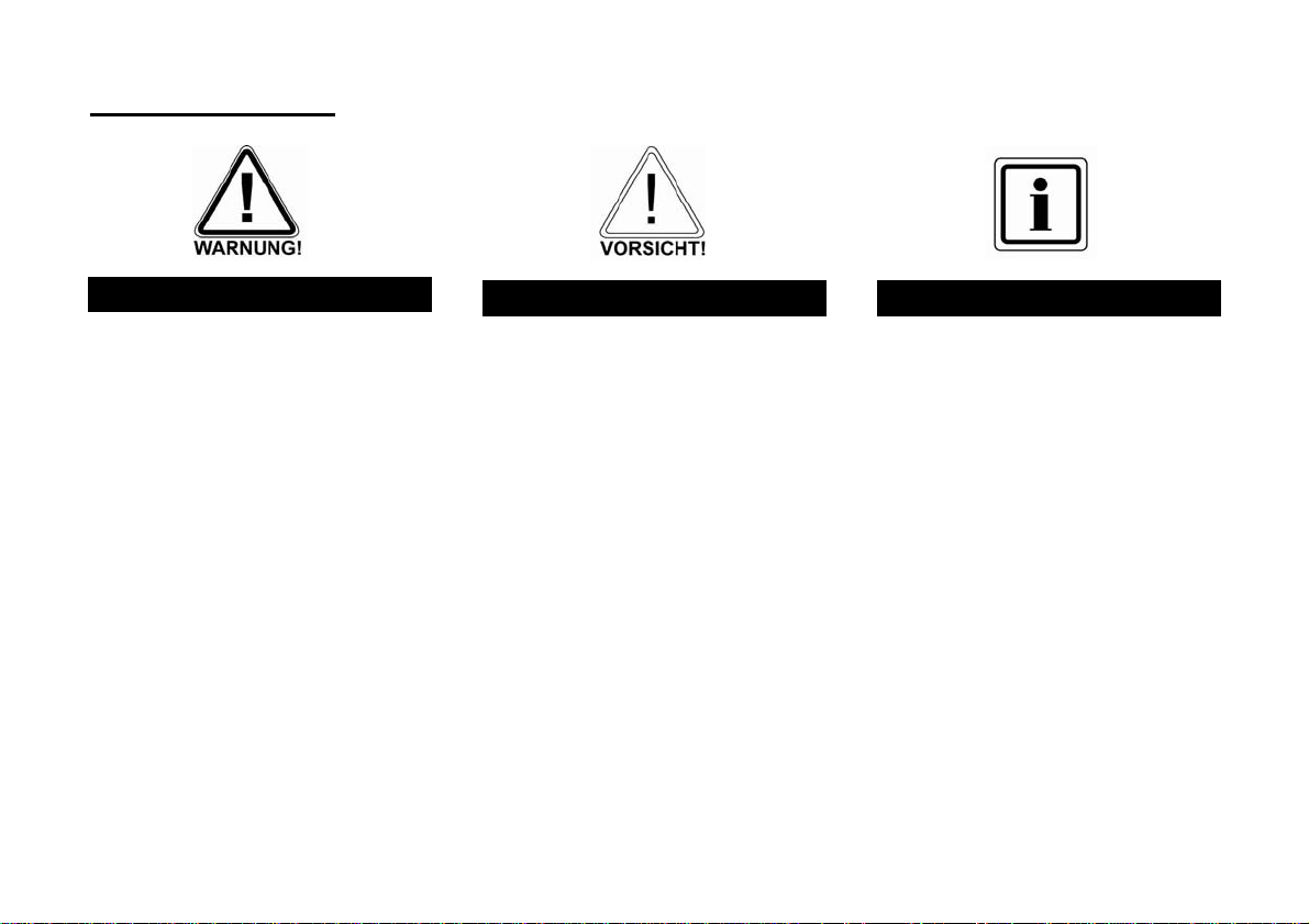
3. Safety information
!WARNING!
To avoid fire and injury, please note the following:
• Securely fasten the device in a dry location in the
building.
• Ensure sufficient ventilation for the alarm centre.
• Do not expose the alarm centre to temperatures
under 0 °C or above 50 °C.
• The alarm centre is designed for indoor use only.
• Humidity must not exceed 90% (non-condensed).
• Ensure that no metal objects can be inserted into the
equipment from outside.
• Ensure that the power supply is disconnected before
carrying out any work on the alarm centre.
!Caution!
Please observe the following precautionary measures
to ensure trouble-free operation of your system.
• The alarm centre is supplied with power from the
built-in PSU.
• The PSU is connected to the 230 V AC domestic
mains network over a separate, electrically protected
line.
• Connection work to the domestic mains network is
subject to country-specific regulations.
• Emergency standby power is supplied by an internal
rechargeable battery.
• The maximum power consumption of the connected
components must not exceed 1 A at any time.
• Always replace fuses with ones of the same rating,
never higher.
!IMPORTANT!
On burglar alarm centres in general:
Improper or careless installation work may lead to
misinterpretation of signals and false alarms. The
costs resulting from the deployment of emergency
services (e.g. fire or police) are borne by the operator
of the equipment. Therefore, please read the
instructions very carefully and follow the installation
instructions for lines and components precisely.
4
Page 5
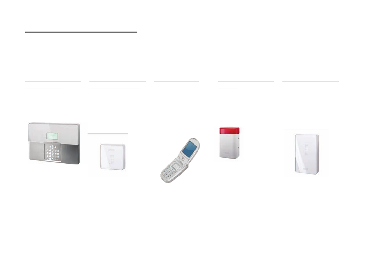
4. System and keypad overview
1 – Chip key reader
2 – Graphic display Multiple-line display
3 – Integrated siren
4 – Activation button
5 – Deactivation button
6 – Control buttons
7 – Keypad alarm keys for panic, fir e,
medical and social call emergencies
8 – Keypad for programming and
operating the alarm centre
9 – Integrated loudspeaker
10 – Integrated microphone
11 – Service flap
5
Page 6
5. Graphic display
The graphic display informs you about all events concerning the wireless alarm system. The following is an overview of the different display messages and their
meaning:
This symbol appears if a voice message
exists that should be listened to. An acoustic
message is issued every time the wireless
alarm system is deactivated. This is as
follows: “You have a message”
This symbol appears when activity
monitoring is activated. Remember to define
the monitoring time period. Activity
monitoring also works when the wireless
alarm system is deactivated.
Menu
Press the button under the menu display.
The wireless alarm system then prompts you
to enter your access code (user code). If the
code is accepted, the user menu is
accessed. All user functions that were
authorised by the installer can be ac cessed
here. Note that some functions in the user
menu require a user code with administra tor
rights (master code).
.
21:00
01/05/2008
Displays the current time and date.
The four black bars stand for the four
individual partitions of the wireless
alarm system. A letter in the black
bar represents the state of th e
partition (1–4). The letters and their
meaning:
U: Unset (deactivated)
S: Set (activated)
P: Part Set (internally activated)
Note: A letter is only displayed in the
partition (bar) when at least one
detector is present in this partition.
This symbol indicates an error in the
wireless alarm system that must be
resolved immediately. For a
summary of the different error
displays and their meaning , see the
table at the end of these instructi o ns.
To display the error, press the button
under the display.
You are then prompted to enter a
valid user code.
6
Page 7
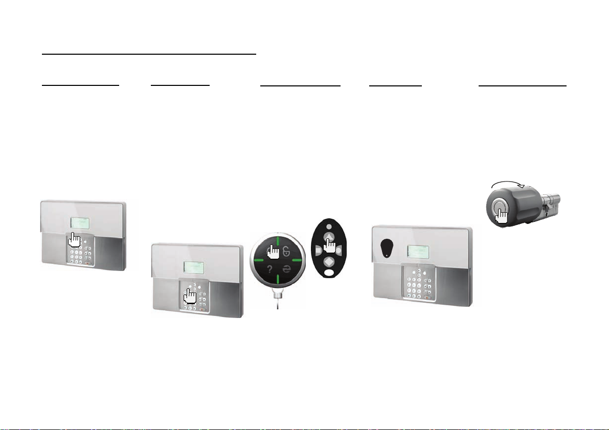
6. Activating the wireless alarm system
The wireless alarm system can be activated in a variety of ways. The system emits an acoustic message. Depending on whether a partition or the complete system
is activated, the message is: “Partition activated” or “Alarm system activated”.
6.1. Fast activation
Please note that this
function can also be
deactivated to prevent
unauthorised operation of
the system. This function is
located in the installer
menu under System
Options -> User access ->
Quick set.
To activate the complete
wireless alarm system,
simply press the active key
as shown.
6.2. User code
If the fast activation
function is deactivated, a
user code is also needed to
activate the system. If the
system has only one
partition, then simply enter
your user code. The
partition for which this user
code is valid is then
activated. If your user code
is valid for two or more
partitions, then a selection
of areas that can be
activated is displayed. For
more information, see
chapters 11 and 12
(“Activating partitions” and
“Activating internally”).
6.3. Remote control
You can activate the
complete wireless alarm
system by pressing the
“Fully active” button on the
remote control. The other
buttons on the remote
control can be used for
activating a partition or
activating the wireless
alarm system internally. For
more information, see
chapters 11 and 12
(“Activating partitions” and
“Activating internally”).
FU8100
FU5150
FU5155
6.4. Chip key
The chip key can be used
to fully activate/deactivate
the wireless alarm centre or
a partition. The chip key is
used in place of the user
code. If a user is authorised
to activate two or more
partitions with a chip key,
then they must decide
which partition to activate
after holding the chip key
against the system. For
more information, see
chapters 11 and 12
(“Activating partitions” and
“Activating internally”).
6.5. Wireless cylinder
The wireless cylinder can
also be used to fully
activate the system or a
partition. To activate the
wireless alarm system, first
press the button on the
cylinder and then lock the
door. The alarm system is
activated after the door is
locked.
7
Page 8
7. During the delay time
Provided no errors that prevent ac ti va ti o n ha ve occurred (zone open), the wireless alarm system starts the confi g ur ed exit delay time. The system emits an acoustic
message. Depending on whether a par ti tion or the complete system is activated, the m essa ge is:
“Partition activated” or
“Alarm system activated”
During this period, you must leave the premises.
A continuous tone sounds duri n g th e delay time. This tone is also emitted by the info module (if fitted).
Some zones may be left open during activation and the exit delay time (Final Exit, Entry Route). However, these zones must be closed be fore the delay time expires
– otherwise, a local alarm is triggered.
When “Final Exit” or “Entry Rout e” zones are open, a pulse tone is emit ted during the exit delay time un til all zones are closed.
8. Unsuccessful activation
There are two different situati ons here:
a) The delay time was not started.
b) The delay time was started.
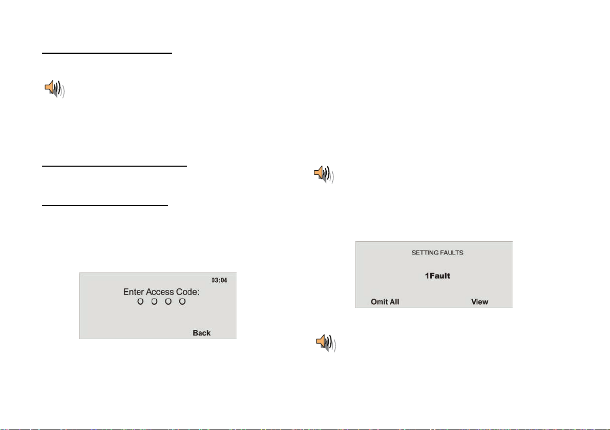
8.1. Delay time was not started
The system does not start the delay time due to a system error.
If you have attempted to a ctivate the system using:
• Fast activation
• Arming station
• Remote control
• Wireless cylinder
then the following display is shown:
An acoustic warning is also issued.
This is as follows:
“The alarm system cannot be activated”
Enter a valid user code in the system and proceed as shown here.
If you have attempted to activate the system usi ng :
• User code
• Chip key
then the display shows the current error.
Select Omit All, to stop monitoring of the zone(s). The d ela y time st arts when
the error is omitted. An acoustic message is played.
“The alarm system is activated with omitted zones”
8
Page 9
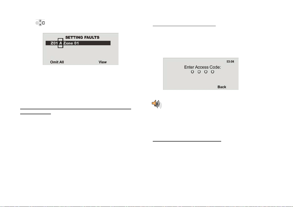
Using the control button, select the item under View to display the error.
The following graphic displ ay is shown:
The wireless alarm system now sh ows all zones that are open or have an
error. The entry following the zone number directly in front of the zone name is
important here. These entri es have the following meanings:
A: Alarm
T: Tamper
Close the zones until the display shows 0Faults, or omit the zones and
remove them from surveillance.
8.2. Notes on system activation with compulsory hidden
(omitted) zones
In order to facilitate system operation, it is possible to hide open zones
automatically when the system is activated. It is then possible to leave the
premises for a short time without needing to close all doors and windows.
Omitted zones remain hidden for the entire activation period and d o not trigger
any alarms.
IMPORTANT:
Only important entry and exit zones shou l d be automatically omitted (e.g. front
door, cellar door, back door etc).
Automatic omission of zones can be made in two ways:
a) Automatic omission with confirmation
b) Automatic omission without confirmation
Automatic omission with confirmation
System is activated by:
• Fast activation
• Remote control
• Arming station
• Chip key
• Wireless cylinder
The following display is shown:
An acoustic warning is also issued. Thi s is as follows:
“The alarm system cannot be activated”
When this message is heard, all opened zones with the “FS” (Force Set) zone
attribute can be automatically omitted in the following ways:
• By pressing the active key on the remote control again
• By entering your user code and pressing the active key on the remote
control
The alarm system is then activated.
Automatic omission without confirmation
System is activated by:
• Fast activation
• Remote control
• Arming station
• Wireless cylinder
All opened zones with the “FS” (Force Set) zone attribute are automatically
omitted and the alarm system is activat ed .
9
Page 10
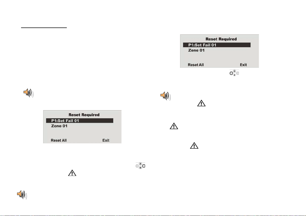
8.3. Delay time started
The alarm system starts the delay time, but with a pulsed tone ins tead of a
continuous tone. This indicates that one or more zones are still open.
Close these zones within the delay time so that a continuous tone is emitted
again.
If these zones are not closed within the delay time, a local alarm is triggered
after the time expires.
Acknowledge this alarm by either entering a valid user code or sending a
deactivation signal using the r emote control (wireless cyli nder).
The system acknowledges the alarm confirmation with an acoustic message.
This is as follows:
“Warning! An alarm has been triggered. A system reset is
required.”
The reason for the alarm is shown on the graphic display of the system. For
example, the following grap hic di splay is shown:
Note: The graphic display disappears after 30 seconds.
The alarm can only be reset on the system itself. The alarm cannot be reset
over the remote control, wireless cylinder or arming station.
If the graphic display has already disappeared, press the control bu tton
under the exclamation mark (
). You are prompted to enter your user
code. After entering the user code, an acoustic message is played.
This is as follows:
“ Warning! An alarm has been triggered. A system reset is required.”
The following graphic display is shown after entry of the correct user code or
immediately after the alar m is ac knowledged:
To reset the alarm, press the co ntrol button
under Reset.
The system can carry out the reset when the ca use of the alarm has been
cleared. The system acknowl ed ge s th e al ar m reset with an acoustic message.
This is as follows:
“The alarm system has made the reset”.
The exclamation mark (
If the cause of the alarm is not cleared (e .g. the tamper contact of the detector
) in the display disappears.
is still open or the technical zone is still triggered), then the alarm cannot be
reset. No acoustic acknowledgement of the reset is received. The exclamation
mark (
) in the display remains in place. Remedy the cause of the alarm
and then reset the alarm again.
After the alarm is reset and confirmed acoustically by the system, the
exclamation mark (
) in the display should disappear . If this is not the
case, then a system fault has occurred. For more information, see section 19.
Reactivate the system and close the zones within the delay time for
successful activation.
10
Page 11
9. Following successful activation
When the alarm centre is successfully activated (also with automatically omitted zones), an acknowledgement is received after the del ay time has expired. This
acknowledgement can have differe nt forms:
• Acknowledgement tone on the wireless alarm system
• Acknowledgement tone on the info module
• An SMS from the wireless alarm system
• Acknowledgement display on the external wireless siren
• Activation of a switch output on the accessory module
9.1. Acknowledgement
tone on system
The wireless alarm system is
activated after the delay time
has expired. Activation is
acknowledged on the system
by an acoustic signal.
After acknowledgement is received, the system is activated and intrusion into a monitored area results in an alarm. Activated areas are marked with an “S” on the
display.
The wireless alarm system must be deactivated before entering the monitored area again. Deactivation can be carried out in several different ways.
Beep beep
9.2. Acknowledgement
tone on info module
After the delay time has
expired and the system has
been successfully activated,
the info module acknowle dges
activation with an acoustic
signal. At the same time, it
shows an active state via the
red LED.
Beep beep
9.3. SMS message
The alarm centre sends an
SMS after the delay time has
expired. This message sho ws
who activated the system and
when. In certain
circumstances, transmission
of the SMS can be slightly
delayed.
9.4. Acknowledgement
on siren
The alarm system sends a
message to the external siren
after the delay time has
expired. This activates the
strobe for about 5 seconds.
This flashes 3 to 5 times in
acknowledgement.
FLASH
FLASH
FLASH
9.5. Accessory module
All types of acknowledgement
displays can be triggered
using the accessory module.
These include LEDs, exterior
lights or additional buzzers.
The output can be triggered
continuously (for the entire
activation period) or in pulses.
11
Page 12

10. Deactivating the wireless alarm system
The wireless alarm system can be deactivated in a variety of ways:
• Deactivation of the entire system or a partition with a user code
• Deactivation of the entire system or a par ti ti o n vi a r emote control
• Deactivation of the entire system or a par ti ti o n vi a a chip key
• Deactivation of the entire system or a pa r ti tion via the wireless cylinder
Note: When operating the alarm system with an arming station, please consult the relevant product instructions.
10.1. User code
Enter your user code. If the user code
is authorised for deactivating one
partition only, then this partition is
deactivated immediately. If the user
code is authorised to deactivate more
than one partition, all parti tions are
displayed that can be deactivated with
this user code. Select the partiti on t o
be deactivated.
If the wireless alarm system is not deactivated before you enter a pro t ec ted area (e.g. system operated wi t h a user code or chip key), the delay time usually starts
after the entrance door is opened. Approach the system as specified by the installer and then de activate the areas concerned. Note that an acoustic signal is emitted
by the wireless alarm system during the entry delay time. This signal indicates that surveillance is still active and that you must not deviate fr om the prescribed route,
otherwise an alarm is triggered.
Following succes sful deactivation, the deactivated areas are now marked with an “U” on the di splay. At the same time, the alarm centre emits an acoustic
message. This is as follows:
“The alarm system is deactivated”
10.2. Remote control
Using a remote control, the complete
wireless alarm system can be
deactivated by pressing the
“Deactivate” button. A l l areas which
can be operated with the remote
control are deactivated.
10.3. Chip key
Hold the chip key over the reader on
the alarm system. If the chip key is
authorised for deactivating one
partition only, this partition is now
deactivated. If the chip key is
authorised to deactivate more than
one partition, all partitio ns are
displayed that can be deactivated with
this chip key. Select the partition to be
deactivated.
10.4. Wireless cylinder
Using the wireless cylinder, a
deactivation signal can be sent easi l y
to the wireless alarm system by
unlocking the front door or
withdrawing a trap. All areas which
can be operated with the remote
control are deactivated.
12
Page 13
)
11. Activa ting partitions
If the alarm system is set up so that two or mor e par titions can be monitored independent ly of each other, these partitions c an now be individually activated or
deactivated. A user can now activate/deactivate one or more partitions, depending on the user authorisation. If the entire alarm system is activated, each partition is
also activated. If the user is authorised to activate one partition only, then this partition can be activated by entering the user code. If the user is authoris e d to
activate two or more partitions, then they must now select the partition to be activated. Partitions can also be activated/deactivated using the remote control or the
arming station. The remote control has the same authorisation as its assigned user.
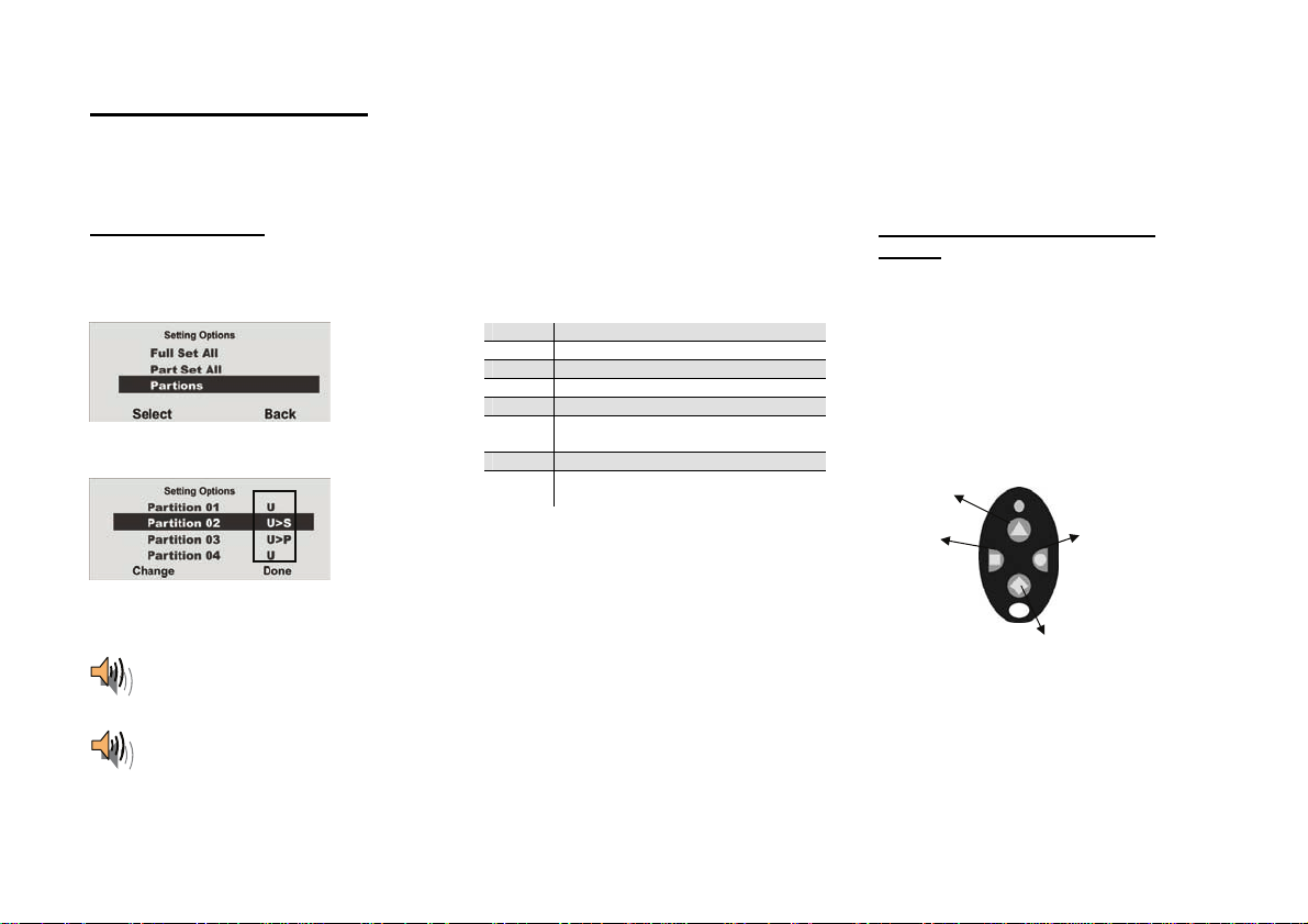
11.1. On the system
Enter your user code or hold your chip key over
the system reader. If you are authorised to
activate more than one partition, the following
graphic display is shown:
Select “Partitions”.
Select the partition to be activated.
When activation is confirmed, the syst em starts the delay time for the correspondi ng pa r tition. At the same time,
Change the settings for this par tition.
The displayed codes next to the partitio n have
the following meanings:
Display Meaning
U This partition remains deactivat ed .
U>P This partition is activated internally.
U>S This partition is activated.
S>U This partition is deactivated.
P>U This partition is deactivated
internally.
S This partition remains activated.
P This partition remains activated
To activate one or more partition s, select U>S
internally.
next to the corresponding partition.
Confirm your entry by pressing Done.
The system then carries out the entered actions
(activation/deactivation).
the system emits an acoustic message. This is as follows:
“Partition activated”
If the user activates all partitions for which they have authorisation, the message is as follows:
“Alarm system activated”
11.2. Using the wireless remote
control
Using the FU5155 / FU5150 remote control unit,
partitions can be activated in two ways:
a) The remote control activates all parti tions
within the user’s authorisat io n.
b) The keys of the remote control unit are
programmed in the user menu t o activate
partitions individually.
Example of key settings:
Complete activation (partitions 1 and 3
Activate
partition
Complete deactivation
See also “System Config”.
Activate
partition 3
13
Page 14
12. Internal activation
In addition to monitoring one or more partitions (i.e. objects or company departments) separately, the system also has an intern al activation option. This type of
activation is often used to monitor the exterior of the object when it is still occupied. In this case, specific detectors within the object such as motion sensors are
removed from surveillance. The same authorisations apply for internal activation as for any other activation. That means that only users who are authorised to
activate the entire system can internally acti va te an ar e a. This also app lie s to remo te controls.
12.1. On the system
Enter your user code or hold your chip key over
the system reader. If you are authorised to
activate more than one partition, the following
graphic display is shown:
Select Part Set All and confirm by pressing
Select.
All areas of the alarm system for which the user
code is authorised are now internally activated.
The system emits the following acoustic
message:
“Alarm system activated internally”
To activate separate partitions internally, select
“Partitions” until the followin g graphic display is
shown:
Select the partition to be activated.
Change the settings for this partition.
The displayed codes next to the partitio n have
the following meanings:
Display Meaning
U This partition remains deactivat ed .
U>P This partition is activated internally.
U>S This partition is activated.
S>U This partition is deactivated.
P>U This partition is deactivated
internally.
S This partition remains activated.
P This partition remains activated
internally.
To activate one or more partition s i nt er n al ly,
select U>P next to the corresponding partition.
Confirm your entry by pressing Done.
The system then carries out the entered actions
(activation/deactivation). If only one partition is
internally activated, the system issues the
following message:
“One partition activated internally”
12.2. Using the wireless remote
control
Partitions can be activated internally using the
wireless remote control in two ways:
a) The remote control internally activates all
partitions within the user’s authorisation.
b) The keys of the remote control unit are
programmed in the user menu t o activate
individual partitions internally.
Example of key settings:
1) Complete activation
(partitions 1 and 3)
2) Complete deactivation
3) System status
4) Complete internal
activation
5) Activate partition
3 internally
See also “System Config”.
3
1
2
21
4
5
4
14
Page 15

13. Alarms
The wireless alarm system has three different types of alarm. Depending on the system state (deactivated , internally activated, activated) or triggered alarm zone
(technical alarm, panic alarm, burglar alarm, fire alarm), one of the fol lowing alarms can be triggered:
• Local / internal alarm
• External alarm
• Silent alarm
13.1. Local / internal alarm
In the event of a local alarm, the following are
activated:
• The alarm system siren
• The info module siren
• The external siren only with a local
alarm (the acoustic alarm is active for 3
minutes and the visual alarm is active
until the system is deactivated)
• The relay of the accessory module (if
programmed)
A local alarm is caused by:
• A tamper alarm when the system is
deactivated
• An alarm in the technical zones
• An alarm in each zone of the system
(except zones with entry/exit delay) when
the system is activated (if programmed)
• An unsuccessful activation due to
exceeding the exit delay time
• Exceeding the first entry delay time
Keep calm in the event of an alarm, regardless of the type. Not every alarm is an intrusion. Most alarms have other causes. Check the situation carefully and take
considered action accordingly. Deactivate the system, check the r ea so n for th e al ar m and then reset the alarm. If you receiv e an alarm by telephone, follow the
steps in section 15.
13.2. External alarm
In the case of an external alarm, the following are
activated:
• The alarm system siren
• The info module siren
• The external siren (the acoustic alarm is
active for 3 minutes and the visual alarm
is active until the system is deactivated)
• Alarm transmission by telephone
• The relay of the accessory module (if
programmed)
An external alarm is caused by:
• A tamper alarm when the system is
activated
• An alarm in the 24-hour zones and fire
zones when the system is activated and
deactivated
• An alarm in each zone of the system
(except zones with entry/exit delay) when
the system is activated (if programmed)
• Exceeding the second entry delay time
13.3. Silent alarm
In the case of a silent alarm, the following are
activated:
• No acoustic or visual alarm
• Alarm transmission by telephone onl y
• The relay of the accessory module (if
programmed)
A silent alarm is caused by:
• A panic alarm (if programmed)
• An alarm in each zone of the system
(except zones with entry/exit delay) when
the system is activated (if programmed)
15
Page 16

14. Resetting the alarm
If the alarm system has triggered an ala r m ( whe ther local, external or silent),
then this must first be acknowledged and then reset. To confirm the alarm,
deactivation of the system is sufficient. Follow the instructions described in
section 10.
When the alarm is confirmed, the siren s on the al arm system, info module(s),
external sirens and relay on the universal module are deactivated.
The system acknowledges the alarm confirmation with an acoustic message.
This is as follows:
“Warning! An alarm has been triggered. A system reset is
required.”
The reason for the alarm is shown on the graphic display of the system. For
example, the following grap hic di splay is shown:
Note: The graphic display disappears after 30 seconds.
The system or partition cannot be reactivated (even internally) until the alarm
is reset (exception: automatic system activation).
The alarm can only be reset on the system itself. The alarm cannot be
reset over the remote control, wireless cylinder or arming station.
If the graphic display has already disappeared, press the control bu tton
under the exclamation mark (
code. After entering your user code, you will receive an acoustic message.
This is as follows:
). You are prompted to enter your user
“Warning! An alarm has been triggered. A system reset is
required.”
The following graphic display is shown after entry of the correct user code or
immediately after the alar m is ac knowledged:
To reset the alarm, press the co ntrol button
The system can carry out the reset when the ca use of the alarm has been
cleared. The system acknowledges the alarm reset with an acoustic message.
This is as follows:
“The alarm system has made a reset”
The exclamation mark (
If the cause of the alarm is not cleared (e .g. the tamper contact of the detector
is still open or the technical zone is still triggered), then the alarm cannot be
reset. No acoustic acknowledgement of the reset is received. The exclamation
mark (
activated. Remedy the cause of the alarm and then reset the alarm again.
After the alarm is reset and confirmed acoustically by the system, the
exclamation mark (
case, then a system fault has occurred. For more information, see section 19.
16
) in the display remains in place and the system cannot be
) in the display disappears.
) in the display should disappear . If this is not the
under Reset.
Page 17

15. Alarm transmission by telephone
In addition to alarms from si r ens a nd si gn al lin g de vi ces , th e wirel e ss al ar m
system can also transmit an alarm via telephone (PSTN, ISDN, GSM). There
are two types of alarm transmission by telephone:
• Alarm transmission of a digital protocol to a security centre
• Alarm transmission of a voice message to any telephone
If a connection to a security centre has be en established, the centre reception
confirms the alarm transmission. I f the a l arm is transmitted to a normal
telephone, the called party mu st acknowledge the alarm transmission to
prevent further dial attempts.
This is the made as follows:
1. The call is received on the telephone and is displayed like any other call.
2. Accept the call.
3. Listen to the complete voice message. A distinction is made here between
different alarm causes.
4. The recorded voice message is repeated three times. After the third
announcement, the microphone on t he wi r ele ss alarm centre is activated
and you can listen in to the monitored room. The following tone dialling
commands are also available.
Telephone key
(DTMF)
1 Switch from listen to voice connection
2 Switch from voice to listen connection
3 Switch to listen connection and repetition of the alarm
5 End call to the phone number
9 End all calls
5. If you are able to take action yourself, acknowledge the alarm
transmission by pressing “5” or “9” on y our telephone (DTMF telephones).
6. If you are not able to take action, then end the call or press “5”. The alarm
transmission is continued and other parties are informed.
Meaning
message
16. Remote control by telephone
The alarm centre can call you in the event of an al arm. After listening to the
message, you can send commands to the system by pressing your telephone
keypad. The system informs you of the command status by playing short
tones through the telephone. Hang up the telephone when you are finished.
You can also call the wireless centr e when no alarms are present in
order to check the system:
1. Dial the number of the alarm system:
You should then hear: “beep, beep, beep”
2. Enter your user code.
****
You should then hear: “beep, beep”
Each of the following commands can be us ed. Hang up the phone to end the
call.
Function Key combination
Playback 1
Talk 2
Playback and talk
(to switch back and forth)
Play message 3
End call 5
End all calls 9
Deactivate system #0*0
Activate system #0*1
Activate system internally #0*2
Disable sirens #1*0
Reset system #1*1
Query system #3*
Switch ON output nn #9*nn*1
Switch OFF output nn #9*nn*0
Switch output nn #9*nn*
*
17
Page 18
The alarm centre registers the status of your commands through different
tones:
Beep = Command accepted
Beep, beep = Action carried out
Bup = Action failed
Eeh, oh (three times) = Alarm
Pip, pip, pip, pip, pip = Reset required
17. User menu
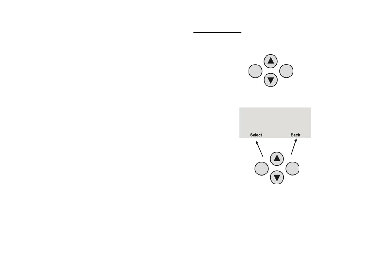
The user menu is graphically designed to be used almost intuitively. The
control buttons are used to navigate around the user menu.
Using the arrow keys, you can navigate up and down within a menu item. The
buttons to the left and right refer to the LCD display and have various
functions.
18
Page 19

18. Settings in the user menu
18.1. First steps in the user menu
In the user mode, proceed as follows:
Press the control button under Menu.
Enter a valid user code or master code.
The default master code is 1234: 1 2 3 4
The wireless alarm system accesses the user menu and the following graphic
display is shown:
Using the control buttons , you can scroll through the men u ite m s in the
installer menu. For a list of the menu items, see the next page.
To select a menu item, press the control button under Select.
To exit a menu item, press the control button under Back.
To exit the user menu, press the control button under Exit.
Overview of menu items in the user menu
18.2.
Among other things, the user m en u ca n be us e d to pr ogram the user code,
omit zones, record voice messages, read the log, activate control functions
and test detectors.
Some functions may have been blocked for the user by the installer. The
following table lists all possible menu items.
Menu item Settings
Voice Memo Play, record and delete voice messages
Omit Zones Omit zones and remove them from surveillance
Users Install, edit and delete u sers
View Log Read log entries
Facilities On/Off Activate/deactivate additional functions (door chime,
Test Test functions on the alarm centre and detectors
System Options Enter date and time, activate remote maintenance ,
Follow Me Enter the follow me number
Outputs On/Off Control manual outputs
Telephone Call Start manual telephone call
The user menu is equipped with a time control. If there is no input within
30 seconds, the user menu is exited automatically.
voice prompt and activity monitoring)
summer/winter time, communication information
19
Page 20

18.3. Recording voice messages
To record a message, proceed as f oll ows:
Select the Voice Memo menu item.
By pressing Select you can record a voice message.
The wireless alarm centre enabl e s the user to record individual
voice messages. These voic e m essages can be listened to and
deleted at any time. The system infor m s th e user of the
existence of a voice message when the wireless alarm system is
deactivated.
This allows you to leave messa ges for other persons.
If Select was confirmed using the control button, recording begins and the
following graphic display is shown:
Recording can be stopped at any time by pressing Done.
Recording stops automatically after 30 seconds. The recording is saved
automatically after it is stopped.
,
You can now select the displayed options.
Option Meaning
Play
Message
Record
Plays back the recorded voice message.
Starts the recording again. The old message is deleted.
Message
Delete
Message
Exit the menu item by pressing Back.
Deletes a saved voice message.
20
Page 21

18.4. Omitting zones
If necessary, you can remove zones from surveillance (e.g. if a detector is
defective or a zone cannot be closed).
Select the Omit Zones menu item.
The system displays all trained zones . S elect the zone where the settings
should be changed.
The settings are as follows: M = Monitored / O = Omitted (not monitored)
The setting can be changed her e.
When the settings have been made, finish data entry by pressing Done.
These zones are not monitored when the wireless alarm system is activated.
The next time the alarm system is deactivated, these zones are
automatically included again and have to be removed again from
monitoring manually.
18.5. Installing users
As an administrator, you can use your code (master code) to install further
users for the wireless alarm system. Up to 50 us ers can be installed on the
system. This menu item is also used for training the remote control, the
emergency and panic detectors and the chip key.
Select the User
You can now edit user settings, add a new user or delete an existing user
together with all settings.
To edit the user settings, first select the Edit User menu item.
menu item.
21
Page 22

18.5.1. Editing users
After selecting the Edit User menu item, the user attributes can be edited.
Chip key Remote control Pendant Panic transmitter
Select the user whose attributes should be edited.
Property Meaning
Name Program the user name.
Type Define the user type.
Partition Define the partitions this user can control.
Code Enter the user code.
Chip key Ad d a chip key to the user.
Telecommands Add a remote control to the user.
Social Care Add a pendant to the user.
Panic Add a panic transmitter to the user. Alt ernatively, you can
also use the dual key function of th e remote control.
Exit this menu item by pressing Back.
18.5.1.1. Changing the user name
Select the user, then the “Name” menu item.
Remove the existing name by pressing Delete, then enter a new user name.
Enter letters via the keypad. Letter-to-key assignment:
Save the new user name and exit the menu it em by pr essing OK.
22
Page 23

18.5.1.2. Changing the user type
Select the user type:
• Normal User
• Administrator
In contrast to the normal user
different settings in the user menu. The normal user
, the administrator can make many
can only change
their user code, but cannot create u ser s or make changes to the system
settings.
18.5.1.3. Defining partitions
User authorisations are defined in this menu. In this way, different users can
control different partitions. The settings also refer to the chip key trained for
this user.
The system shows all four partitions. Sel ec t the partition whose setting
should be changed.
The settings are as follows:
• Yes = This user can activate and deactivate this partition
• No = This user cannot activate or deactivate this partition
23
Page 24

18.5.1.4. Changing the user code
Select the Code menu item.
Enter the new four-digit code vi a th e keypad. After entering the last digit, you
are prompted to repeat your input.
If both codes are identical, the code is saved.
18.5.1.5. Training and removing chip keys, remote controls, pendants
and panic transmitters
Follow the instructions in t he display to train the correspondi ng components to
the wireless alarm system. The following page shows how to train the different
components.
Components can be removed from a user in t he same way as they are
assigned. In this case, follow the instructions in th e dis play.
24
Page 25

Training the chip key
Select Tag. The system
prompts you to hold the chip
key over the system reader.
Hold the chip key over the
alarm system as shown in the
picture. When the system
detects the chip key, it
confirms that training was
successful.
Note: One chip key can be
trained for ea ch user. The
user code remains active.
Training the remote
control without panic
function (FU5155)
Select Telecommands. The
system prompts you to press a
button on the remote control
until the system has detected
and trained the remote control.
Any key can be pressed here.
When the system detects the
remote control, it confirms that
training was successful.
Note:
Up to 20 remote control
units (FU8100, FU5155/5150)
can be trained.
More than one remote
control can be assigned to a
user.
Training the remote
control with panic
function (FU5150)
Training a remote control with
panic function is made in the
same way as the remote
control without panic function
(see above). However, the
panic function is also trained in
this case. The separate
training or deletion of the panic
function is not necessary, and
is also not possible.
When the system has
recognised the remote control,
the panic function and other
normal remote control
functions are activated.
Note:
Up to 20 remote control
units (FU8100, FU5155/5150)
can be trained.
More than one remote
control can be assigned to a
user.
Training the wireless
cylinder
Select Telecommands. The
system prompts you to train
the wireless cylinder. Press
the button on the wireless
cylinder and lock the door. The
cylinder sends a learn
message to the wireless alarm
system.
When the system detects the
wireless cylinder, it confirms
that training was successful. A
wireless cylinder is treated
like a remote control unit,
i.e. up to 16 remote controls
and/or wireless cylinders
can be trained. Depending on
which user the wireless
cylinder was trained to, the
user can activate or deactivate
the corresponding areas.
Example: If user 2 is
authorised to control partitions
2 and 3, these two partitions
are activated via the wireless
cylinder.
Training the pendants
(emergency call
transmitters)
The wireless alarm system
can process two types of
emergency transmitters.
These are “Social Care” and
“Panic”, which have the s ame
meaning as the emergency
key functions on the system
keypad. Select Social Care or
Panic. The system then
prompts you to press the
emergency transmitter.
When the system detects the
emergency transmitter, it
confirms that training was
successful.
Note: Up to 16 emergency
transmitters can be trained.
This number includes the
other emergency
transmitters (social care and
panic).
One emergency tr an s mitter
and one panic transmitter
can be trained per user.
25
Page 26

15.5.2. Adding users
To add a new user to the wireless alarm system, select the Add User menu
item.
You are now guided through the remaining menu items as described in the
“Editing users” section.
15.5.3. Deleting users
To delete a user and all user settings (such as remote controls and chip keys),
select the Delete User menu item. Select the corresponding user by pressing
Delete.
Confirm your entries by pressing OK. The user is then deleted. Please note
that at least one administrator must be pr esent in the system.
For this reason, the user 01 with administrator properties cannot be deleted.
IMPORTANT: To change or delete a single component of a user, select
Edit User
and then select the item you wish to change or delete.
26
Page 27

18.6. View in g t h e lo g
This function enables you to read the event log. This log contains the last 250
events together with the date and time. The log cannot be deleted. When the
log is full, the oldest event is delete d to make room for a new event (FIFO
memory).
Select the View Log menu item.
Select the corresponding report trigger. To display report trigger details such
as time and date, select Expanded.
Exit this menu item by pressing Back.
If Expanded was confirmed with the control butt on , t he following graphic
display is shown:
You can also scroll through the log using the control buttons
. To return
to the list, select the List menu item. To exit the log, select Back.
The following list gives an overview of the entries and their meaning.
Entry Meaning
Lid Tamper The tamper contact of the housing lid was
opened.
Lid Tamp Restore The tamper alarm of the housing lid was
confirmed.
Telecmd U-- Low Bat The remote control battery of user -- must be
replaced.
Pendant U-- Low Bat Th e pendant of user -- must be replaced.
Batt Missing There are no batteries in the system.
Batt Fault Restore Batteries were fitted in the system.
Invalid No entry.
Configuration Fail Error when storing the programming.
Codes Defaulted All user codes were reset.
Defaults Loaded The factory default settings were loaded.
System Startup The system has been put into operation.
System Tamper Tamper detection on a detector or syste m .
System Tamper Rstr The tamper alarm was confirmed.
U-- On-Site The installer has accessed the installer menu.
U-- Off-Site The installer has exited the installer menu.
Entry Meaning
U-- Change U-- User -- has edited us er --.
U-- Delete U-- User -- has deleted user --.
U-- Ptn # Set User -- has activated partition #.
U-- Ptn # UnSet User -- has deactivated partition #.
27
Page 28

System Rearmed The system has automatically reactivated itself
following an alarm.
U-- Z== Omit User -- has omitted zone ==.
Fire Z== Alarm Zone == has triggered a fire alarm.
Fire Z== Restore The fire alarm was confirmed.
Fire Reset The fire alarm was confirmed on the control
panel.
PA Z== Alarm Zone == has triggered a panic alarm.
PA Z== Restore The panic alarm of zone == was confirmed.
U-- System Reset User -- has reset the system.
Fire K== Alarm A fire alarm was triggered on the control panel.
PA K== Alarm A panic alarm was triggered on the c ontrol panel.
Medical K== Alarm A medical emergency was triggered on the
control panel.
Burg Z== Alarm Zone == has triggered an burglar alarm.
Set Fail Z== System activation has failed due to an error i n
zone ==.
Burg Z== Restore The burglar alarm was confirmed.
Tamper Z== Zone == has triggered a tamper alarm.
Tamper Z== Restore The tamper alarm was confirmed.
K== Excess Keys The extra keys on the control panel were
activated.
Low Bat Z== The battery of the detector in zone == must be
replaced.
Low Bat Z== Rstr The battery in this zone is OK again.
RF Jamming Wireless jamming has occurred. The wireless
transmission was disturbed for at least 30
seconds within one minute.
RF Jamming Restore The jamming report was confirmed.
RF Sup Fail Z== Supervision has failed in zone ==. This zone has
not reported to the system for 2 hours.
RF Sup Rstr Z== The supervision failure message was confirmed.
PSTN Line Fault Error in the analogue telephone line.
PLGON Line Fault Transmission error via ISDN/GSM.
Entry Meaning
PSTN Line Restore Error in analogue telephone line was confirmed.
PLGON Line Restore Error in ISDN/GSM transmission was confirmed.
Comms Fail Error during transmission to security centre.
U-- Remote Download User -- has carried out remote maintenance.
U-- Download Fail User -- has an error in remote maintenance.
AC Fail Power failure.
AC Restore The power failure was confirmed.
Low Battery The system battery is not charged.
Low Batt Restore The battery error was confirmed.
Battery Load Fail The battery cannot be charged.
Tech Z== Alarm Zone == has triggered a technical alarm.
Tech Z== Restore The technical alarm was confirmed.
U-- Time/Date User -- has changed the date or time.
Soak Fail Z== Detector test in zone == has failed.
Test Call The system has made a test call.
Bad Checksum Mis interpretation in wireless transmission.
U-- Soc. Emergency A social care emergency has been tri gg ere d.
Social Inactive The social care function has been deactivated.
Key Box Open Z== The key box in zone == was opened.
Key Box Close Z== The key box in zone == was closed.
Key Sw Set Z== The key sw itch of zone == has activated the
system.
Key Sw Unset Z== The key switch of zone == has deactivated the
system.
U-- Ptn # Reset User -- has reset the par ti tion.
RF Failure Error in wireless transmission.
RF Failure Restore Wireless transmission is OK again.
Social Emergency K== A social care emergency was triggered o n th e
control panel.
Fire Restore K== The fire alarm was confirmed .
PA Restore The panic alarm was confirmed.
U-- Ptn # PtSet User -- has activated a partition internally.
PA U-- Alarm User -- has triggered a panic alarm.
RF PA U-- Low Bat The panic detector battery must be replaced.
Entry Stray Z== Zone == has triggered an alarm during the entry
28
delay time.
Page 29

A
18.7. Additional functions
In this menu, a user can switch the functions assigned to them by the installer
on and off.
Select the Facilities On/Off menu item.
Seven menu items are available for selection.
Function Meaning
Chime When deactivated, the system emits a signal tone if
a door chime detector is triggered. This signal tone
can be deactivated here.
Voice Prompts Activates an d de activates the voice prompt.
Activity Monitor Activates and deactivates activity monitoring of the
social care call.
B’Light Brightness Sets the backlight brightness in 4 steps.
B’Light Always Backlight is per manently on/off.
Wall Light Off: Wall light is permanently off.
On: Wall light is illuminated when the
system is active, flashes in the
event of an alarm and is not lit
when the system is deactivated.
Timed: Wall light is illuminated for 5 minutes
when activated and flashes in the event of
an alarm.
Zone Name Prompts
ctivated: Yes/no
Voice Prompts: 2 second prompt for each
zone
29
Page 30

18.8. Test
This menu is used to test the different alarm centre functions.
Select the “Test” menu item.
Select the function you wish to test.
To end the test, select Back.
Function Meaning
Siren Tests local alarms on the system and external sirens.
Loudspeaker Tests the loudspeaker function.
Keypad Tests the keypad function.
Walk Test Tests the functions of the individual zones.
Outputs Tests the wired and wireless outputs.
Telecommands Tests the remote control (telecommand) functions.
Pendants Tests the social care transmitter (pendant) functions.
PA Detector Tests the panic detector functions.
Tag Tests the chip key (tag) functions.
Siren
Press On/Off to activate and dea ct i vate the siren. On or Off at the top-right of
the display indicates whether or not the siren should be heard.
Loudspeaker
Press Play/Stop to play the voice messages over the loudspeaker. You can
listen to all voice messages saved in the system. Playing is shown at the topright of the display and the voice message should be heard.
Keypad
Press each button once. The corresponding character is shown on the
display in response. Press the double keys simultaneously to start the test.
Press OK to end the test.
Walk Test
A list of all detectors installed on the system is shown on the display. Go
through the property and trigg er all detectors one after the other. Each time a
detector is triggered, the al ar m centre emits a double tone and “S” is
displayed at the end of the row for the corresponding detector. Please note
that “24 Hour” and “Fire” zones cannot be test ed.
30
Page 31

Outputs
A list of all outputs installed on the system is shown on the display. Select the
output to be tested. Press Done to end the test.
IMPORTANT: Ensure that nobody attempts to activate the WAM using a
remote control or social care transmitter during the test. When the test
is ended, check whether the output has the required status.
Telecommands
Press any key on the remote control. The remote control user, the key
pressed according to the wireless centre programming and the signal strength
are all shown on the display. Press all keys on the remote control one after
another.
Pendants
Press the button on the pendant. The identity of the user assigned to the
pendant is displayed.
PA Detector
Press the button on the panic transmitter. The identit y of th e user assigned to
the panic transmitter is displ ayed.
Tag
Hold the chip key (tag) at the top-left corner on the front of the alarm centre.
The identity of the user assigned to the chip key is shown on the display.
18.9. System configuration
This menu is used to change individual system settings, such as date and
time, outputs and remote controls.
Select the System Config menu item.
Select the item where the settings should be changed. Exit this menu item by
pressing Back.
The items have the following meanings:
31
Page 32

Function Meaning
Set Date & Time Select this point to enter the date and time of the
wireless alarm system.
Edit Outputs Select this point to change the time s of th e m anual
output. The manual output is activated at the first
time entered and deactivat ed at the second.
Note: Outputs can be sw itched on and off using
a suitable remote control or by selecting the
“Outputs On/Off” user menu.
Telecommands Select this point to newly allocate the remote control
buttons. The fourth button of the remote control can
also be programmed here.
Note: If you do not have a remote control, press
“NO TELECOMMANDS”. A list of registered
remote controls and their users is show n on the
display. Select the remote control to be edited.
The corresponding keys can be selected using
keys. Select the option on the display
the
you wish to use.
Call Downloader Manually activates the selection of a phone number
for the remote control (if installed).
Summer/Winter
Time
Selects between automatic and manual change
from summer to winter time.
Message Volume Selects the volume of the voice message.
Panel Sounder Vol The volume of operating, info and alarm tones
can be set in 5 steps here.
Installer access Defines whet h er th e ad mi n i strator code must be
entered in addition to the installer code to access
the installer menu .
About Comms Shows information on the available communication
paths.
Additionally, the following alarm centre information
is displayed.
With inserted ISDN module:
None
With inserted GS M module:
GSM IMEI module
GSM signal strength
GSM network name
GSM phone number
With inserted ethernet module:
IP address
IP subnet mask
IP gateway address
MAC address
With inserted GPRS module:
GSM IMEI module
GSM signal strength
GSM network designatio n (e .g . 26 201 for D1)
GSM phone number
Auto Set/Unset Using this option, you can activate and deactivate
the system according to a week planner. Further
details can be found in the following example.
Follow the instructions in the display to make settings. The display guides you
through the settings.
32
Page 33

18.9.1. Week Planner
Only users with administration rights can install this function.
The system should be activated and deactivated according to the time and day of the week.
First create a weekly plan of the activation and deactivation times.
Each day, up to 5 data records can be programmed for activation (start) and 5 data records can be programmed for deactivation (end).
Monday Tuesday Wednesday Thursday Friday Saturday Sunday
Time P1* P2 P3 P4 P1 P2 P3 P4 P1 P2 P3 P4 P1 P2 P3 P4 P1 P2 P3 P4 P1 P2 P3 P4 P1 P2 P3 P4
00:00 00:00
01:00
02:00
03:00 S S
04:00
05:00
06:00
07:00 07:20 07:20
08:00
09:00
10:00
11:00
12:00
13:00
14:00
15:00
16:00
17:00
18:00 18:00
19:00 P
20:00 19:59
21:00 20:00
22:00
23:00 S
00:00
*P = Partition
33
Page 34

18.9.2. Activation / deactivation of the week planner
Access the user menu using the administrator code (default = 1234) and create a week planner.
Access the menu and enter your access code.
In the System Config menu, select the Auto Set/Unset menu item.
Select Y for activation.
Æ
Æ
Set (activated)
Activation Y
Deactivation
X
Activation N
18.9.3. Selecting the weekday
Select the weekday in the week planner.
Æ
Monday Tue sday Wednesday
Time P1 P2 P3 P4 P1 P2 P3 P4 P1 P2 P3
00:00 00:00
01:00
02:00
03:00 S
04:00
Th
P4 P1
34
Page 35

Y
,
y
P
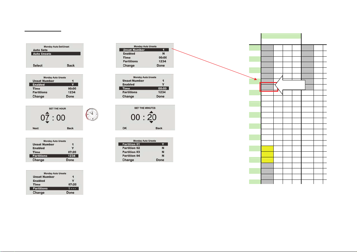
18.9.4. Auto Set
Select the time for Auto Set (00:00).
Select data record 1.
Select activated
Select the activation time.
Set the hour, then press Next to set the minutes and confirm with OK.
Select the “Partitions” menu item
Æ
Æ
Æ
Æ
then change the partitions to Y or N.
Æ
Monday Tuesda
Time P1 P2 P3 P4 P1 P2
00:00 00:00
01:00
02:00
03:00 S
04:00
05:00
06:00
07:00 07:20 07:20
08:00
09:00
10:00
11:00
12:00
13:00
14:00
15:00
16:00
17:00
18:00 18:00
19:00 P
20:00 19:59
21:00 20:00
22:00 S
23:00
Data record
Activation
35
Page 36
r
,
,
y
P
18.9.5. Auto Unset
Select the time for the Auto Unset (07:20).
Select data record 1.
Select activated Y Select the activation time.
Æ
Æ
Set the hou
then press Next to set the minutes and confirm with OK.
Select the “Partitions” menu item
End programming by pressing Done.
A data record has now been programmed for Monday with an activation time of 00:00 and a deactivation time of 07:20.
Æ
Æ
then change the partitions to Y or N.
Monday Tuesda
Time P1 P2 P3 P4 P1 P2
00:00 00:00
01:00
02:00
03:00 S
04:00
05:00
06:00
07:00 07:20 07:20
08:00
09:00
10:00
11:00
12:00
13:00
14:00
15:00
16:00
17:00
18:00 18:00
19:00 P
20:00 19:59
21:00 20:00
22:00 S
23:00
Data record
Deactivation
36
Page 37

y
P
18.9.6. Internal and external activ atio n
In this example, partition 1 is switched from internal activation (external perimeter protection) to external activ ati on (completely activated).
The system should have external perimeter protection from 18:00 onwards and a complete activation from 20:00 onwards.
If detectors with the Part Set (P) property are set up for partition 1, you can Menu item in week planner: Use Auto Set to Part Set for
partition 1.
( Installer mode - Detector)
Detector in partition 1 with the property: P
Set 18:00 Unset 19:59
Activation Monday, 20:00 Select the next day (Tuesday) Deactivation Tuesday, 07:20
The change from internal to external activation cannot be made without an interruption of <
1 minute
(e.g. 19:59 Æ 20:00).
(Week Planner)
• Create data record 2 as detailed in the Auto Set and Auto Unset sections.
Set Y, activation time 18:00, Part Set Y and Partitions 1 - - - .
Set Y, deactivation time 19:59 and Partitions 1 - - - .
Part Set: Y for partition 1
• Create data record 3 as detailed in the Auto Set and Auto Unset sections.
Set Y, activation time 20:00, Part Set N and partitions 1 - - - .
Unset time 07:20 on the following day (Tuesday) with data record 1.
Please make sure to use the data record 1 on the next day for deactivation.
There is a danger of losing track of the programming.
Monday Tuesda
Time P1 P2 P3 P4 P1 P2
00:00 00:00
01:00
02:00
03:00 S
04:00
05:00
06:00
07:00 07:20 07:20
08:00
09:00
10:00
11:00
12:00
13:00
14:00
15:00
16:00
17:00
18:00 18:00
19:00 P
20:00 19:59
21:00 20:00
22:00 S
23:00
Data record 1
Data record 2
Monday
Data record 3
Activation
Tuesday
Data record 1
Deactivation
37
Page 38

y
P
18.9.6. Activating and deactivating data records
To deactivate a data record (time period), make changes in the AUTO SET menu.
In AUTO UNSET, change Set to N.
Data record: Data record:
Start deactivated End deactivated
Monday Tuesda
Time P1 P2 P3 P4 P1 P2
00:00 00:00
01:00
02:00
03:00 S
04:00
05:00
06:00
07:00 07:20 07:20
08:00
09:00
10:00
11:00
12:00
13:00
14:00
15:00
16:00
17:00
18:00 18:00
19:00 P
20:00 19:59
21:00 20:00
22:00 S
23:00
Data record 1
X
Data record 2
Monday
Data record 3
Activation
Tuesday
Data record 1
Deactivation
38
Page 39

18.10. Follow Me
This menu is used for entering the follow me number. This number is dialled
to send a voice message to a telephone of your choice in the event of an
alarm. Apart from the follow me num b er , up to four other telephone numbe r s
can be dialled. These can only be changed in the installer menu. The follow
me number can also be changed in the user menu.
Select the Follow Me menu item.
Enter the new number on the key pad a nd save by pressing OK.
Press Delete to delete a phone number.
18.11. Outputs On/Off
This menu is used to activate or deactivate individual outputs manually.
Only outputs programmed a s manual can be activated.
Select the Outputs On/Off
Select the output where the settings should be changed.
The selected output can be activated or deactivated
End your entry by pressing Done.
menu item.
by pressing “Change”.
39
Page 40

18.12. Telephone Call
This menu is used to start a telephone call manually and test the telephone
line or GSM connection. The system uses the integrated loudspeaker and
microphone to establish a voice connection.
Select the “Telephone Call” menu it em.
Enter the new number using the keypad. The number is dialled b y pressing
“OK”. The number is removed by pressing “Delete”.
The system starts to dial the entered number and establishes a voice
connection.
19. Error displays
There are several errors that can occ ur dur ing normal system operation.
These errors do not immediately trigg er an al ar m or prevent system activation.
All errors should be cleared immediately by the user or reported to the
installer as they indicate a malfunction. Errors and error-clearing measures
are entered in the event log. An error always results in the following graphic
displays (except after an alarm):
The exclamation mark (
error, press the control button
are prompted to enter your user code. The error is then display ed. For
example, the following graphic display is shown:
See the following pages for displayed errors, their meaning and possible
causes.
Confirm by pressing OK after dealing wit h th e er ror. The exclamation mark
) disappears.
(
) in the display indicates en error. To display the
under the exclamation mark ( ). You
40
Page 41

•
•
•
•
19.1. Errors, meanings, causes and suggested solutions
Displayed error Meaning Possible causes Suggested solutions
AC Fail The 230 V AC system
power supply is missing.
WAM__PSU Fail 230 V AC power supply is
missing in the accessory
module.
Batt Low No battery power supply
to the system.
WAM Low Batt No battery po wer supply
to the accessory module.
• The main fuse of the PSU on the wireless
alarm system is not fitted correctly or is
defective.
• The connecting cable between the system
and the base plate is not inserted correctly.
• The main power supply to the PSU of the
base plate has failed or the power cable
was not fitted correctly.
• PSU in base plate is defective.
• The mains power cable to the 12 V power
supply is not connected correc tly.
• The PSU is not supplied with power.
• The PSU that supplies power to the
accessory module is defective.
• The inserted batteries are not full y charged.
• The lead-acid battery has not yet been
charged.
• No lead-acid battery was connected.
Replace the main fuse with one of the same
rating.
• Check that the fuse is correctly fitted.
• Check the correct installation of the system to
the base plate and plug the connecting cable
into the correct base plate socket.
• Check that your mains power fuse is active for
the system. Is there a 230 V power supp ly?
• Check the correct connection between t h e m ains
power line and the PSU clamp.
• Contact your installer.
Check the correct installation of the 12 V DC
connecting cable.
• Check that the PSU is inserted and the red LED
on the PSU is lit.
• Contact your installer.
This error should disappear when the batteries
are fully charged.
• After a maximum of 4 hours, the batteri es are
charged and this display disappears.
This error should disappear when the battery is
fully charged.
• Check the correct installation of the 6 V, 1. 2 Ah
lead-acid battery in the accessory module.
41
Page 42

•
•
•
•
•
•
Displayed error Meaning Possible causes Suggested solutions
Low Batt Z__ No battery power supply
in zone __.
WAM__ SUP Fail Supervision signal from
the accessory module
has failed.
Zone Supervision
Faults
Supervision signal from
detector of zone __ has
failed.
Jamming Jamming of wireless
communication for more
than 30 seconds inside a
• The battery capacity in the detector of zone
__ is almost exhausted.
• The accessory module outside the wireless
range of the system.
• The wireless unit on the accessory module
has failed.
• The detector is outside the wireless range
of the system.
• The wireless unit of the detector has failed.
• Intentional or natural disturban ce within the
wireless band.
Change the detector battery wit hi n 14 days.
Check wireless communication betwee n the
system and the accessory module usi ng the
wireless testing box.
• Install the accessory module in a more suitable
location.
• Contact your installer.
Check wireless communication between the
system and the transmitter using t he wi r ele ss
testing box.
• Install the detector in a more suitabl e location.
• Contact your installer.
Contact your installer.
minute.
PSTN Line Fault Analogue transmission
path has failed.
PLGON Line Fault Digital transmission path
has failed.
Failure of GSM
connection.
• The analogue telephone connection is not
connected correctly to the telephone line.
• The transmission path has been
programmed for an analogue telephone,
although this is not used.
• The ISDN telephone connection is not
connected correctly to the telephone line.
• The GSM device is not connected to the
network.
Check the correct connection of the analogue
telephone line.
• Check whether the analogue line is engaged for
a long period or disconnected .
• Contact your installer. Programming must be
changed.
Check the correct connection of the ISDN
telephone line.
• Check that the SIM card is correctly inserted and
that you still have credit.
• Use the “About Comms” item in the user menu
to check the signal strength and the stat e of the
GSM module. If the signal strength is too weak,
no transmission can take place.
42
Page 43

20. Declaration of conformity
The declaration of conformity to the applicable guidelines has been made available and signed by Security Center management. It is available under www.abus-sc.eu.
21. User menu overview
43
Page 44

44
Page 45

Amendments to the operating manual (UK)
Secvest 2WAY
FU8006
S/W ≥ 5.04.22
A1 - I
Page 46

1. Preface
Dear customers,
We constantly develop our product range in order to provide our customers with optimal products incorp orating
state-of-the-art technology. The new software release for the Secvest 2WAY includes optimised wo rkflows and an
extended function range. These improvements can be found in the following document.
2. Software status (01.08.2009)
The information as detailed below can be found under the “Installer Menu”
Main S/W: 5.04.22 50 Hz
Part No.: 11952474
RF S/W: 05.11
Dansk [SC]: 3.07
or
English : 3.18
or
Italiano [SC]: 3.02
Æ “About Panel” menu item.
A1 - II
Page 47

3. New menu items in user menu
3.1. Secvest Key 2WAY wireless cylinder, item no. FU59xx
• Testing
User Menu
Select the corresponding Secvest Key 2WAY (Door Lock 1, Door Lock 2, Door Lock 3 or Door
Lock 4). The wireless cylinder functions can be tested here.
“Unlocked” is shown on the Secvest 2WAY display when the door is unlocked. “Locked” is shown
when the button on the Secvest Key 2WAY wireless cylinder is pressed and the door is then
locked. The received signal strength is also shown.
Æ Testing Æ Secvest Key
A1 - III
Page 48

3.2. FU8100 wireless remote control
User Menu
• “Y” (yes) is the default factory setting. The alarm centre is activated immediately when the FU8100 remote
• When “N” (no) is selected, the actions set under the following positions are started wh en the remote control
• Pay attention to the reception time of the FU8100 remote control for feedback (approx. 10 seconds).
Æ System Config Æ Telecommands Æ 2 Way Instant Set Æ 2 Way Instant Set Y
2 Way Instant Set N
control is pressed.
is pressed:
Installer Menu
The exit delay time is started for “Timed Set” or “Silent Set”, or the corresponding action is started for
“Final Door Set” or “Instant Set”.
After this period has elapsed, the FU8100 remote control cannot display any more feedback.
Æ Partitions Æ Partition 0x Æ Ext Mode Æ Timed Set
Final Door Set
Instant Set
Silent Set
A1 - IV
 Loading...