

Page 1
Secvest 2Way
BOM-No 12156890
O P E R A T I N G I N S T R U C T I O N S
1
Page 2

Preface
Introduction
Dear customers,
Many thanks for your purchase of the SECVEST 2Way wireless alarm centre. This
device is built according to state-of-the-art technology.
It complies with current domestic and European regulations.
Conformity has been proven, and all related certifications are available from the
manufacturer on request (www.abus.com).
To ensure safe operation, it is your obligation to observe these installation instructions!
In the event of questions, please contact your local specialist dealer.
Everything possible has been done to ensure that the contents of these instructions
are correct.
However, neither the author nor ABUS Security-Center GmbH & Co. KG can be held
liable for loss or damages caused directly or indirectly by these instructions, whether
real or alleged.
We reserve the right to make changes to these instructions without prior notice.
© ABUS Security-Center GmbH & Co. KG, 10-2011, V5-07-52
This wireless alarm centre is used to secure your property in combination with
detectors and transmitters. Among others, it can be used to protect your company
premises, house, garage, summer house or weekend cottage.
The alarm centre registers unauthorised break-ins by switching outputs that can be
connected to visual, acoustic or silent alarm transmitters.
The alarm centre contacts and connected components must be kept free of moisture
(bathrooms and similar surroundings must be strictly avoided).
Use of this product for other than the described purpose may lead to damage of the
product.
Other hazards such as short-circuits, fire, electric shock etc. are also possible. The
PSU is designed for operation with a 230 V AC / 50 Hz mains power supply.
No part of the product may be changed or modified in any way.
Connection to the public power network is subject to country-specific regulations.
Please be aware of applicable regulations in advance.
2
Page 3

2. Contents
2. CONTE NTS ................................................................................................................ 3
3. SAFET Y INFOR MATION............................................................................................. 5
4. SYSTE M AND KEY PAD OVERVIEW ........................................................................... 6
5. GRAP HIC DISP LAY ..................................................................................................... 7
6. ACTIV ATING TH E WIRE LESS ALAR M SYSTEM .......................................................... 8
6.1. FAST ACTIVATION .................................................................................................... 8
6.2. USER CODE............................................................................................................. 8
6.3. REMOTE CONTROL ................................................................................................... 8
6.4. CHIP KEY ................................................................................................................ 8
6.5. WIRELESS CYLINDER ................................................................................................. 8
7. DURING THE D ELAY TIME......................................................................................... 9
8. UNSUCCE SSFUL AC TIVAT ION ................................................................................... 9
8.1. DELAY TIME WAS NOT STARTED .................................................................................. 9
8.2. NOTES ON SYSTEM ACTIVATION WITH COMPULSORY HIDDEN (OMITTED) ZONES ................. 10
Automatic omission with confirmation................................................................ 10
Automatic omission without confirmation .......................................................... 10
8.3. DELAY TIME STARTED ............................................................................................. 11
9. FOLL OWING SUCC ESSFUL ACTIV ATION ................................................................. 12
9.1. ACKNOWLEDG EMENT TONE ON SYST EM ..................................................................... 12
9.2. ACKNOWLED GEMENT TONE ON I NFO MODULE............................................................. 12
9.3. SMS MESSAGE...................................................................................................... 12
9.4. ACKNOWLEDGEMENT ON SIREN ................................................................................ 12
9.5. ACCESSORY MODULE .............................................................................................. 12
10. DEA CTIVAT ING THE WIR ELESS AL ARM SYST EM .................................................. 13
10.1. USER CODE......................................................................................................... 13
10.2. REMOTE CONTROL ............................................................................................... 13
10.3. CHIP KEY ............................................................................................................ 13
10.4. WIRELESS CYLINDER ............................................................................................. 13
11. ACTIV ATING P ARTITIO NS ..................................................................................... 14
11.1. ON THE SYSTEM ................................................................................................... 14
11.2. USING THE WIRELESS REMOT E CONTROL ................................................................... 14
12. INTE RNAL AC TIVATION ........................................................................................ 15
12.1. ON THE SYSTEM ................................................................................................... 15
12.2. USING THE WIRELESS REMOT E CONTROL ................................................................... 15
13. ALAR MTYPE S ........................................................................................................ 16
13.1. LOCAL / INTERNAL ALARM ..................................................................................... 16
13.2. EXTERNAL ALARM ................................................................................................ 16
13.3. SILENT ALARM ..................................................................................................... 16
14. RESE TTING T HE ALAR M ........................................................................................ 17
15. ALAR M TRANSMISSIO N BY TELEPH ONE .............................................................. 18
16. REMOT E CONT ROL BY TELEPHO NE ...................................................................... 18
17. USER ME NU .......................................................................................................... 20
18. SETT INGS IN TH E USER MENU .............................................................................. 20
18.1. FIRST STEPS IN TH E USER MENU .............................................................................. 20
18.2. OVERVIEW OF MENU ITEMS IN THE USER MENU ......................................................... 21
18.3. RECORDING VOICE MESSAGES ................................................................................. 21
18.4. OMITT ING ZONES ................................................................................................. 22
18.5. INSTALLING U SERS ................................................................................................ 23
18.5.1. Editing users ............................................................................................. 23
18.5.1.1 . Changing the user name ...................................................................................... 24
18.5.1.2 . Changing the user type ........................................................................................ 24
18.5.1.3 . Defining partitions ................................................................................................ 25
18.5.1.4 . Changing the user code........................................................................................ 2 5
18.5.1.5. Training and removing chip keys, remote controls, pendants and panic
transmitter s .......................................................................................................................... 26
15.5.2. Adding users ............................................................................................. 27
15.5.3. Deleting users........................................................................................... 27
18.6. VIEWING THE LOG ................................................................................................ 28
18.7. ADDITIONAL FUNCTIONS........................................................................................ 30
18.8. TEST.................................................................................................................. 31
3
Page 4

18.9. SYSTEM CONFIGURATION ...................................................................................... 33
18.9.1. Week Planner ........................................................................................... 36
18.9.2. Activ ation / deactivation of the week planner ......................................... 37
18.9.3. Selecting the weekday ............................................................................. 37
18.9.4. Auto Set ................................................................................................... 38
18.9.5. Auto Unset ............................................................................................... 39
18.9.6. Internal and external activation .............................................................. 40
18.9.7. Activating and deactivating data records ................................................ 41
18.10. FOLLOW ME..................................................................................................... 42
18.11. OUTPUTS ON/OFF ............................................................................................ 42
18.12. TELEPHONE CALL ............................................................................................... 43
19. ERR OR DISP LAYS .................................................................................................. 44
19.1. ERRORS, MEANINGS, CAUSES AND SUGGESTED SOLUTIONS ........................................... 45
20. NEW OPE RATING MODE F OR SOCIA L CARE ME SSAGES ..................................... 47
21. DEC LARATION O F CONF ORMITY.......................................................................... 47
4
Page 5
3. Safety information
!WARNING!
To avoid fire and injury, please note the following:
x Securely fasten the device in a dry location in the
building.
x Ensure sufficient ventilation for the alarm centre.
x Do not expose the alarm centre to temperatures
under 0 °C or above 50 °C.
x The alarm centre is designed for indoor use only.
x Humidity must not exceed 90% (non-condensed).
x Ensure that no metal objects can be inserted into the
equipment from outside.
x Ensure that the power supply is disconnected before
carrying out any work on the alarm centre.
!Caution!
Please observe the following precautionary measures
to ensure trouble-free operation of your system.
x The alarm centre is supplied with power from the
built-in PSU.
x The PSU is connected to the 230 V AC domestic
mains network over a separate, electrically protected
line.
x Connection work to the domestic mains network is
subject to country-specific regulations.
x Emergency standby power is supplied by an internal
rechargeable battery.
x The maximum power consumption of the connected
components must not exceed 1 A at any time.
x Always replace fuses with ones of the same rating,
never higher.
5
!IMPORTANT!
On burglar alarm centres in general:
Improper or careless installation work may lead to
misinterpretation of signals and false alarms. The
costs resulting from the deployment of emergency
services (e.g. fire or police) are borne by the operator
of the equipment. Therefore, please read the
instructions very carefully and follow the installation
instructions for lines and components precisely.
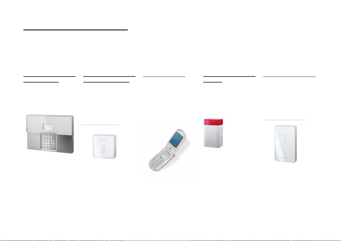
Page 6
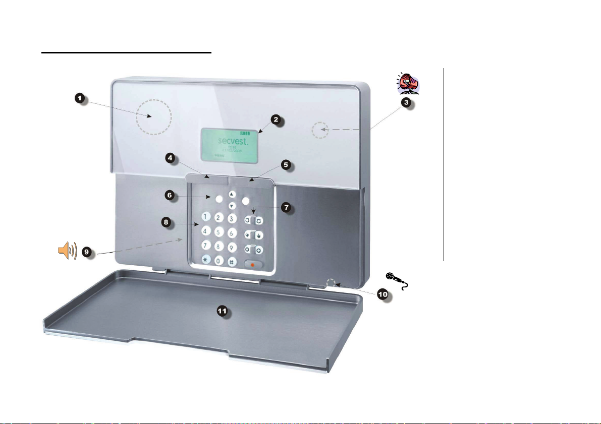
4. System and keypad overview
1 – Chip key reader
2 – Graphic display Multiple-line display
3 – Integ rated si ren
4 – Activation button
5 – Deactivation button
6 – Control butt ons
7 – Keypad alarm keys for panic, fire,
medical and social call em ergencies
8 – Keypad for programming and
operating the alarm centre
9 – Integ rated loudspeaker
10 – Integ rated microphone
11 – Service flap
6
Page 7
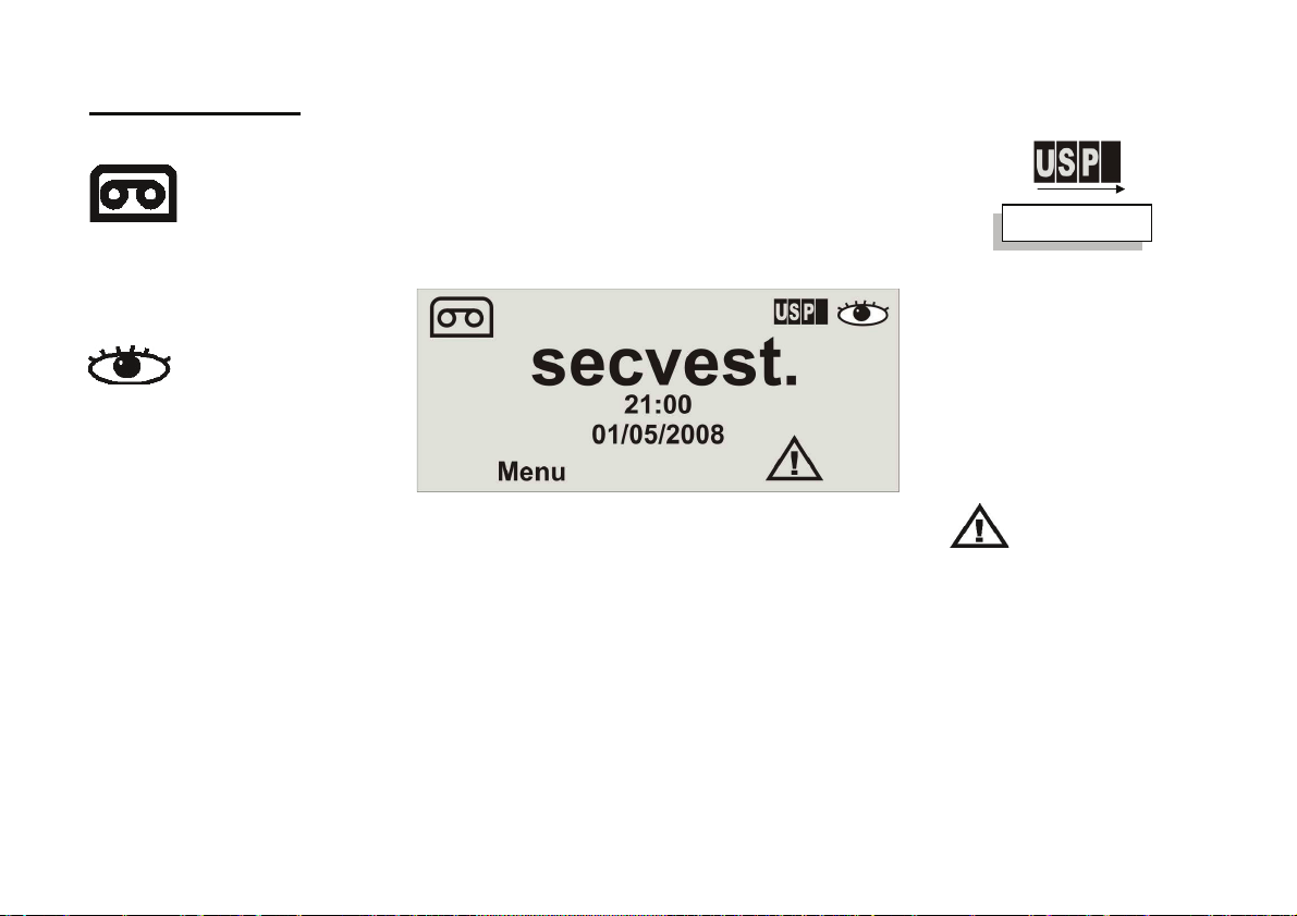
5. Graphic display
The graphic display informs you about all events concerning the wireless alarm system. The following is an overview of the different display messages and their
meanin g:
Teilbereiche 1-4
zn 1
This symb ol appears if a voic e message
exists that should be listened to. An acoustic
messag e is issu ed every tim e the wirel ess
alarm system is d eactivated . This is as
follows: “You have a message”
This symbol appears when activity
monit oring is activated. Remember to define
the monitoring time period. Activity
monit oring also works when the wireless
alarm system is d eactivated .
.
The four b lack bars stand for the four
individual partition s of the wireless
alarm system. A letter in the black
bar represents the state of the
partition (1–4). The letters and their
meanin g:
U: Unset (deacti vated)
S: Set (activated)
P: Part Set (intern ally acti vated)
Note: A letter is only displayed in the
partition (bar) when at least one
detector is present in this partition.
4
Menu
Press the button under the menu display.
The wireless alarm system then prompts you
to enter your access code (user code). If the
code is acce pted , the user menu is
accessed. All user fun ctions that were
authorised by the installer can be accessed
here. Note that some functions in the user
menu req uire a user code with administrator
right s (master cod e).
21:00
01/05/2008
Displays the current t ime and date.
7
This symb ol indicates an error in the
wireless alarm syst em that must be
resolved immed iately. For a
summary of the different error
displays and their meaning, see the
table at the end of these in structions.
To display the error, press the button
under the display.
You are then promp ted t o enter a
valid user code.
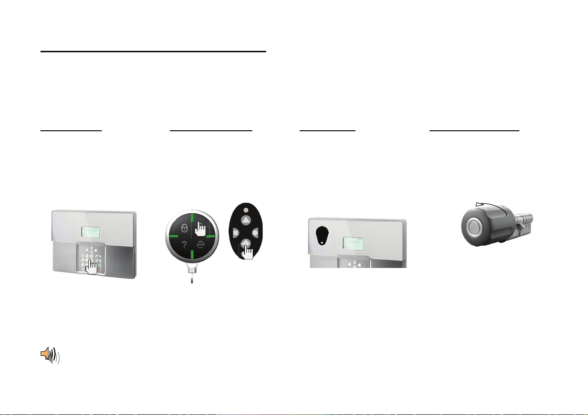
Page 8
6. Activating the wireless alarm system
The wireless alarm system can be act ivated in a variet y of ways. The system emits an acoust ic message. Dep ending on whether a partition or the complete system
is activated, th e message is: “Partition activated” or “Alarm syst em act ivated”.
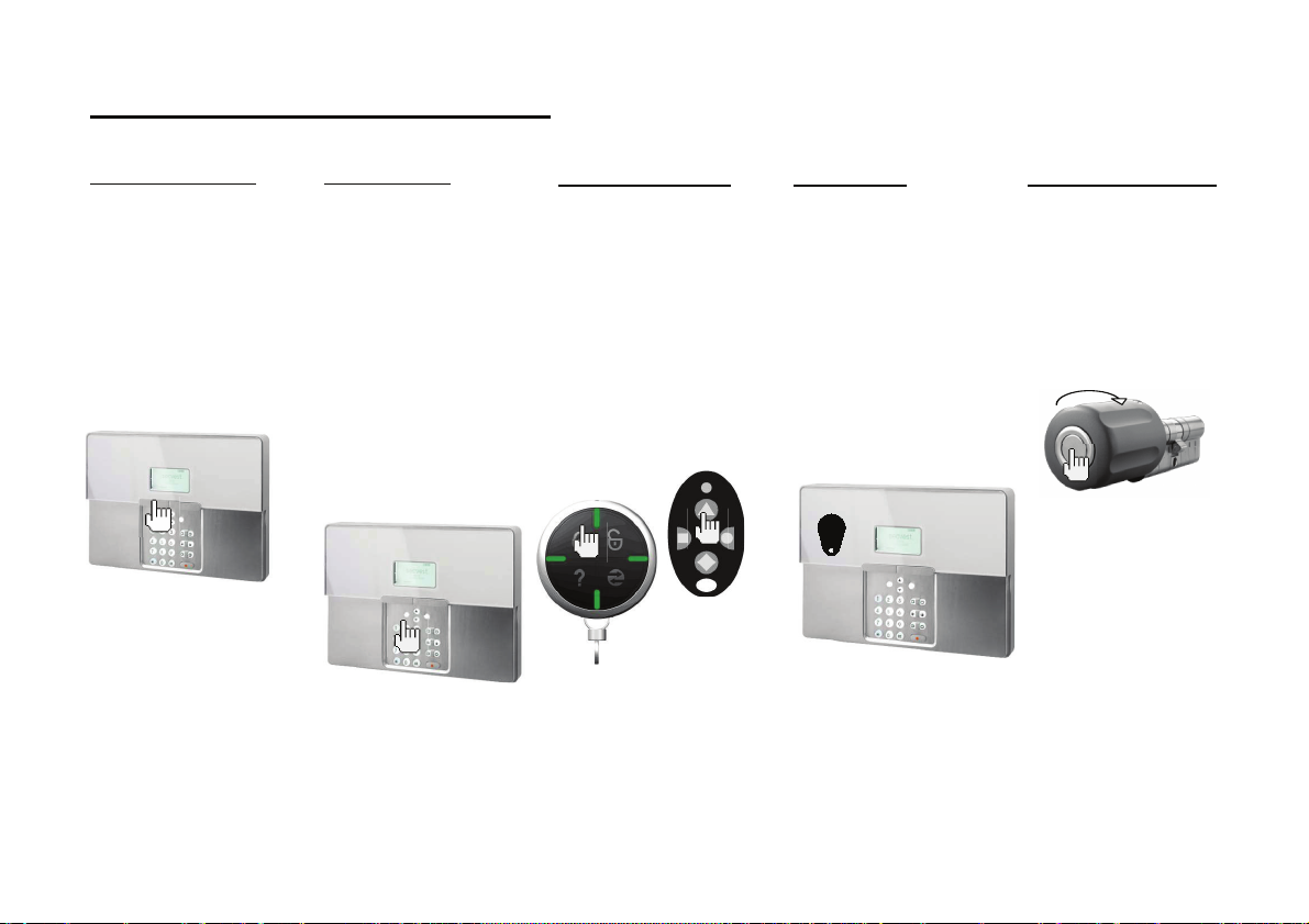
6.1. Fast activation
Please note that this
function can also be
deactivated to prevent
unauthorised operation of
the system. This function is
located in the installer
menu under System
Options -> User access ->
Quick set.
To activate the complete
wireless alarm system,
simply press the active key
as shown.
6.2. User code
If the fast activation
function is deact ivated, a
user cod e is also needed to
activate the system. If the
system h as only one
partition, then simply enter
your user code. The
partition for which this user
code is valid is then
activated. If your user code
is valid for two or more
partitions, then a selection
of areas th at can be
activated is displayed. For
more information, see
chapt ers 11 and 12
(“Activating partitions” an d
“Activating internally”).
6.3. Remote control
You can act ivate th e
complete wireless alarm
system b y pressing the
“Fully active” button on the
remote control. The other
buttons on the remote
control can be used for
activating a partition or
activating the wireless
alarm system internally. For
more information, see
chapt ers 11 and 12
(“Activating partitions” an d
“Activating internally”).
FU5150
FU5155
FU8100
6.4. Chip key
The chip key can be used
to fully activate/deactivate
the wireless alarm centre or
a partition. The chip key is
used in place of th e user
code. If a user is authorised
to activat e two or m ore
partitions with a chip key,
then they m ust decide
which partition to activate
after holding the chip key
against the system. For
more information, see
chapt ers 11 and 12
(“Activating partitions” an d
“Activating internally”).
6.5. Wireless cylinder
The wireless cylinder can
also be used to fully
activate the system or a
partition. To activate the
wireless alarm syst em, first
press the button on the
cylinder and then lock the
door. The al arm syst em is
activated after the door is
locked.
8
Page 9
7. During the delay time
Provided no errors that prevent activation have occu rred (zone open ), th e wireless alarm system starts th e configured exit delay tim e. The system emits an acoustic
messag e. Depend ing on whether a p artition or the complete system is activated, the message is:
“Partition activated” or
“Alarm system activated”
During this period, you must leave the premises.
A continuous tone sounds during the delay time. This tone is also emitted by the info module (if fitted).
Some zones may be left open during activation and the exit dela y time (Final Exit, Entry Route). However, these zones mu st be closed before the delay time expires
– otherwise, a local alarm is triggered.
When “Final Exit” or “Entry Route” zones are op en, a pulse tone is emitted during the exit d elay time until all zones are clos ed.
8. Unsuccessful activation
There are t wo different situations here:
a) The delay time was not started.
b) The delay time was started.
8.1. Delay time was not started
The system does not start the delay time due to a system error.
If you have at temp ted to activate the system using:
x Fast activation
x Arming station
x Remote control
x Wireless cylinder
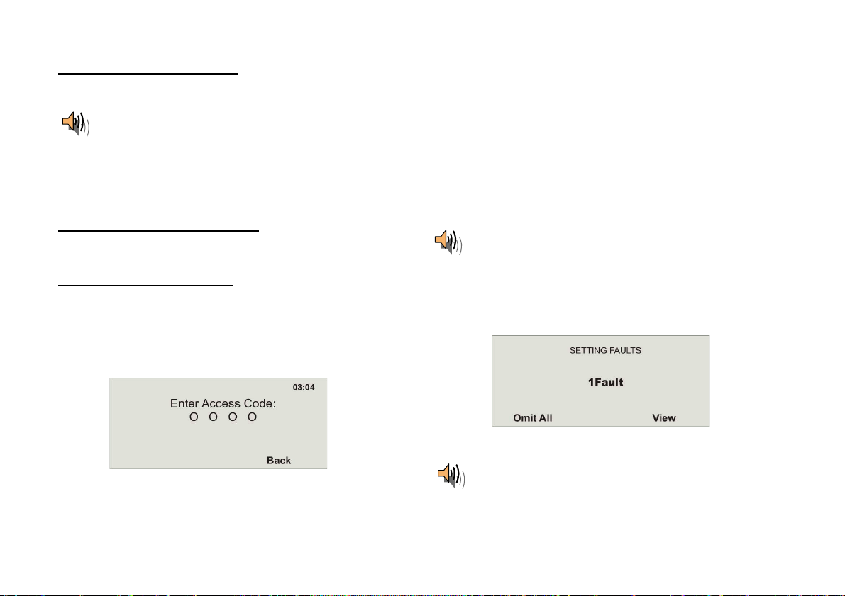
then the following display is shown:
An acoustic warning is also issued.
This is as follows:
“The alarm system cannot be activated”
Enter a valid user code in the system and proceed as sh own here.
If you have at temp ted to activate the system using:
x User code
x Chip key
then the display shows the current error.
Select Omit All, to stop monitoring of the zon e(s). The delay time starts when
the error is omitted. An acoustic message is played.
“The alarm system is activated with omitted zones”
9
Page 10
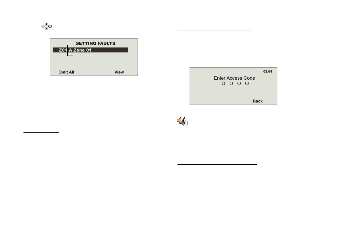
Using the control button , select the item under View to disp lay the error.
The following graphic display is shown:
The wirel ess alarm s ystem now shows all zones th at are open or have an
error. The entry following the zone numb er direc tly in fron t of the zone nam e is
important here. These ent ries have the foll owing meanings:
A: Alarm
T: Tamper
Close the zones until the display shows 0Faults, or omit the zones an d
remove them from surveillance.
8.2. Notes on system activation with compulsory hidden
(omitted) zones
In order to facilitate system operation, it is p ossible to hide open zones
automatically when the system is activated. It is then possi ble to leave the
premises for a short time without needing to close all doors and windows.
Omitted zones remain hidden for the entire activation period and do not trigger
any alarm s.
IMPORTANT:
Only importan t entry and exit zones shou ld be automatically omitted (e.g . front
door, cellar door, back door etc).
Automatic omission of zones can be made in two ways:
a) Automatic omission with confirmation
b) Automatic omission without confirmation
Automatic omission with confirmation
System is activated by:
x Fast activation
x Remote control
x Arming station
x Chip key
x Wireless cylinder
The following display is shown:
An acoustic warning is also issued. This is as follows:
“The alarm system cannot be activated”
When this message is heard , all opened zones with the “FS” (Force Set) zone
attribute can be automatically omitted in the following ways:
x By pressing the active key on the rem ote con trol again
x By entering your user code and pressi ng the active key on the rem ote
control
The alarm system is then activated.
Automatic omission without confirmation
System is activated by:
x Fast activation
x Remote control
x Arming station
x Wireless cylinder
All open ed zones with the “FS” (Force Set) zone attribute are au tomatically
omitted and the alarm system is act ivated.
10
Page 11
8.3. Delay time started
The alarm system starts the delay time, but with a pu lsed tone instead of a
continuous tone. This indicates that one or more zones are still open.
Close these zones within the delay time so t hat a continuous tone is em itted
again.
If these zones are n ot closed within the delay time, a local alarm is triggered
after th e time expires.
Acknowledge th is alarm by either en tering a valid user code or sending a
deactivation si gnal using the remote control (wireless cylinder).
The system acknowledges t he alarm confirm ation with an acoustic message.
This is as follows:
“Warning! An alarm has been triggered. A system reset is
required.”
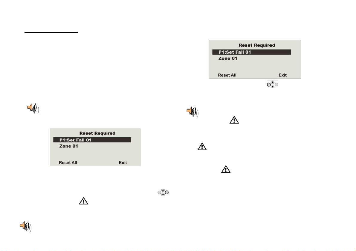
The reason for the alarm is shown on the graphic display of the s ystem. For
example, the following graphic display is shown:
Note: The graphic display disappears after 30 seconds.
The alarm can only be reset on the system itself. The alarm cannot be reset
over the remote control, wireless cylinder or arming station.
If the graphic display has already disappeared, press the control button
under the exclamation m ark (
code. After entering th e user code, an acou stic message is played.
This is as follows:
“ Warning! An alarm has been triggered. A system reset is required.”
). You are prompted to ent er your user
The following graphic display is shown after entry of the correct user code or
immediately after the alarm is ackn owledg ed:
To reset the alarm, press the control button
The system can carry out the reset when the cause of the alarm has been
cleared. The system ackn owledges the alarm reset with an acoustic message.
This is as follows:
“The alarm system has made the reset”.
The exclamation m ark (
If the cause of the alarm is not cleared (e.g. the tamper contact of th e detector
is still open or the technical zone is still triggered), then the alarm cannot be
reset. No acoustic acknowledgement of the reset is received. The excl amation
mark (
and then reset the alarm again.
After th e alarm is reset and confirmed acoustically by the system, the
exclamation mark (
case, then a system fault has occurred. For more inform ation, see section 19 .
Reactivate the syst em and close t he zones within the delay tim e for
successful activation.
11
) in the display remains in place. Remedy the cause of the alarm
) in the display disappears.
) in the display should disappear. If this is not the
under Reset.
Page 12
9. Following successful activation
When the alarm cen tre is su ccessfully activated (also with autom atically omitted zones) , an ackn owledgement is received after the delay time has expired. This
acknowledgement can h ave differen t form s:
x Acknowledgement tone on the wireless alarm system
x Acknowledgement tone on the info module
x An SMS from the wireless alarm system
x Acknowledgement disp lay on the external wireless siren
x Activation of a switch output on the accesso ry module
9.1. Acknowledgement
tone on system
The wireless alarm system is
activated after the delay time
has expired. Act ivation is
acknowledged on the system
by an acoustic si gnal.
Beep beep
After ackn owledg ement is received, the system is activated and intrusi on into a monitored area resu lts in an alarm. Activated areas are marked with an “S” on the
display.
The wireless alarm system must be deactivated before entering the m onitored area again. Deact ivation can be carried out in several different wa ys.
9.2. Acknowledgement
tone on info module
After the delay time has
expired and the system has
been su ccessfully activated,
the info module ackn owledg es
activation with an acoustic
signal. At the same time, it
shows an act ive state via the
red LED.
Beep beep
9.3. SMS message
The alarm centre sends an
SMS after the delay time has
expired. This messa ge shows
who activated the system and
when. In certain
circumstances, transmission
of the SMS can be slightly
delayed.
12
9.4. Acknowledgement
on siren
The alarm system sends a
messag e to the extern al siren
after the delay time has
expired. This activates the
strobe for ab out 5 seconds.
This flashes 3 to 5 times in
acknowledgement.
FLASH
FLASH
FLASH
9.5. Accessory module
All types of ackno wledgem ent
displays can be triggered
using the accessory module.
These include LEDs, exterior
lights or additional buzzers.
The output can be triggered
continuously (for the entire
activation period) or in pulses.
Page 13
10. Deactivating the wireless alarm system
The wireless alarm system can be deactivated in a variety of wa ys:
x Deactivation of the entire system or a partition with a user code
then locked for 90 seconds.)
x Deactivation of the entire system or a partition via r emote control
x Deactivation of the entire system or a partition via a ch ip key
x Deactivation of the entire system or a partition via the wirel ess cylinder
Note: When operating the alarm system with an arming station, please consult the relevant prod uct instructions.
10.1. User code
Enter your user code. If the user code
is authorised for deactivating one
partition only, then this partition is
deactivated immediately. If th e user
code is au thorised to deact ivate m ore
than one partition, all partitions are
displayed that can be deactivated with
this user code. Select the partition to
be deact ivated.
If the wireless alarm system is n ot deactivated before you enter a protected area (e.g. system operated with a user code or chip key), the delay time usually starts
after th e entrance door is opened . Approach the syst em as sp ecified by the installer and then deactivate the areas concerned. Note that an acoustic signal is emitted
by the wirel ess alarm system during the entry delay tim e. This signal indicates that surveillance is still active and that you must not deviate from the prescribed route,
otherwise an alarm is triggered.
Following successful deactivation, the deact ivated are as are now marked with an “U” on the d isplay. At the sam e time, the alarm centre em its an acoustic
message. This is as follows:
“The alarm system is deactivated”
10.2. Remote control
Using a remote control, the complete
wireless alarm syst em can be
deactivated by pressing the
“Deactivate” button. All areas which
can be op erated with the remote
control are deacti vated .
(If the code is entered incorrectly four times in succession, the keypad (except for the alarm buttons) is
10.3. Chip key
Hold th e chip key over the read er on
the alarm system. If the ch ip key is
authorised for deactivating one
partition only, this partition is now
deactivated. If the chip key is
authorised to deactivate more th an
one partition, all partitions are
displayed that can be deactivated with
this chip key. Select the partition to be
deactivated.
10.4. Wireless cylinder
Using the wireless cylinder, a
deactivation si gnal can be sent easily
to the wirel ess ala rm system by
unlocki ng the front door or
withdrawing a trap. All areas whic h
can be op erated with the remote
control are deacti vated .
13
Page 14
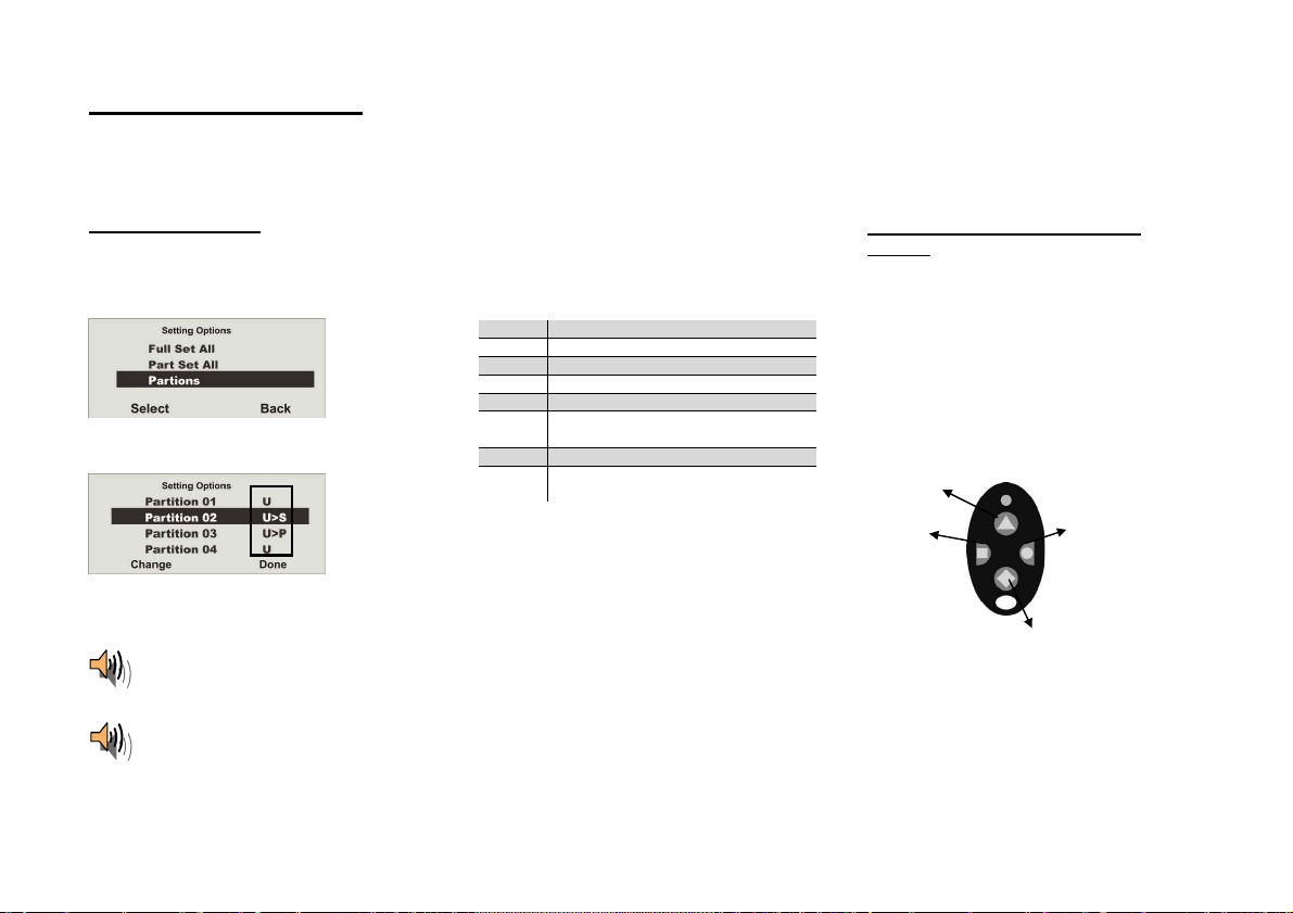
11. Activating partitions
)
If the alarm system is set up so that two or more part itions can be monitored independen tly of each other, these partition s can now be individually activated or
deactivated. A user can now activate/deactivate one or more partitions, depending on the user authorisation. If the entire alarm system is act ivated, each partition is
also acti vated. If the u ser is authorised to activate one partition only, then th is partition can b e activated by entering the user code. If the user is authorised to
activate two or more partitions, then they must now select th e partition to be activated. Partitions can also be activated/deactivated using the remote control or th e
arming station . The remote control has the same au thorisation as it s assig ned user.
11.1. On the system
Enter your user code or hold your chip key over
the system reader. If you are authorised to
activate more th an one p artition, the following
graphic display is shown:
Select “Partitions”.
Select t he partition to be activated.
When act ivation is confirm ed, the system starts the delay time for the correspondin g partition. At the same time,
the system emits an acoustic message. This is as follows:
“Partition activated”
If the u ser activates all partitions for which they have authorisation, the message is as follows:
“Alarm system activated”
Change the sett ings for this partition.
The displayed codes next to the partition have
the following meanings:
Display Meaning
U This partition remains deactivated.
U>P This partition is activated internally.
U>S This partition is activated.
S>U This partition is deactivated.
P>U This partition is deactivated
S This partition remains activated.
P This partition remains activated
To activate one or more partitions, select U>S
next to the corresp onding partition.
Confirm your entry by pressing Done.
The system then carries out the entered actions
(activation/d eactivation).
internally.
internally.
11.2. Using the wireless remote
control
Using the remote control unit, partitions can be
activated in two ways:
a) The remote cont rol activates all p artitions
within the user’s authorisation.
b) The keys of the rem ote control un it are
program med in the user menu to activate
partitions individually.
Example of key settings:
Complete activation (partition s 1 and 3
Activate
partition
Complete deact ivation
See also “System Config”.
Activate
partition 3
14
Page 15
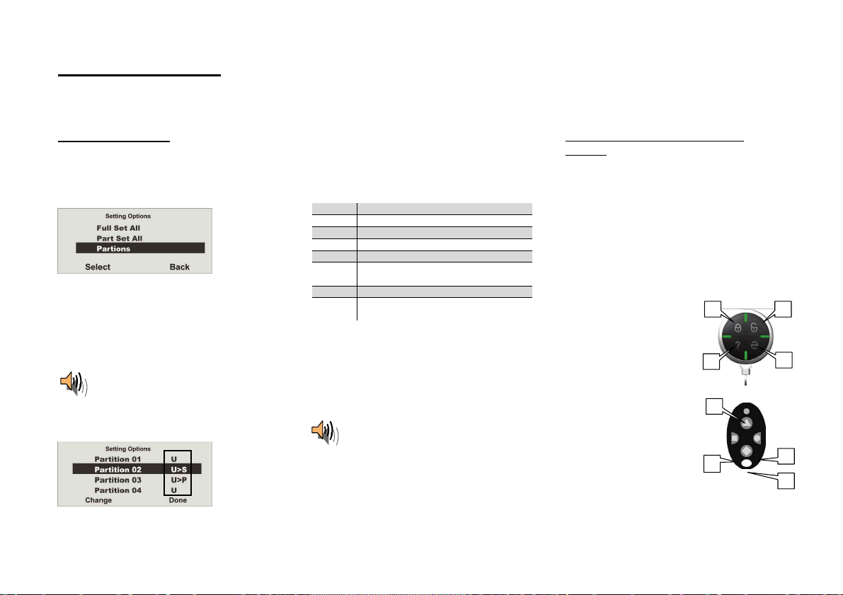
12. Internal activation
In addition to monitoring one or m ore partitions (i.e. ob jects or company departments) separately, the system also h as an internal act ivation option. This type of
activation is often used to monitor the exterior of the object when it is still occupied. In this case, sp ecific detectors within the object such as motion sensors are
removed from surveillance. The sam e auth orisations app ly for internal activation as for an y other act ivation. That means that only users who ar e auth orised to
activate the entire system can internally activate an area. This also applies to remote controls.
12.1. On the system
Enter your user code or hold your chip key over
the system reader. If you are authorised to
activate more th an one p artition, the following
graphic display is shown:
Select Part Set All and confirm by pressing
Select.
All areas o f the alarm system for which the user
code is au thorised are now internally acti vated.
The system emits the follo wing acoustic
messag e:
“Alarm system activated internally”
To activate separat e part itions internally, select
“Partitions” until the following graphic display is
shown:
Select t he partition to be activated.
Change the settings for this partition.
The displayed codes next to the partition have
the following meanings:
Display Meaning
U This partition remains deactivated.
U>P This partition is activated internally.
U>S This partition is activated.
S>U This partition is deactivated.
P>U This partition is deactivated
S This partition remains activated.
P This partition remains activated
To activate one or more partitions internally,
select U>P next to the corresponding partition.
Confirm your entry by pressing Done.
The system then carries out the ent ered actions
(activation/d eactivation). If only one partition is
internally acti vated, the syst em issu es the
following messa ge:
internally.
internally.
“One partition activated internally”
12.2. Using the wireless remote
control
Partitions can be activated internally using t he
wireless remote control in two ways:
a) The remote cont rol internally activates all
partitions within the user’s authorisation.
b) The keys of the rem ote control un it are
program med in the user menu to activate
individual partitions internally.
Example of key settings:
1) Complete activation
2) Complete deactivation
3) System status
4) Complete internal
activation
5) Activate partition
3 internally
See also “System Config”.
1
2
21
4
4
15
Page 16

13. Alarmtypes
The wireless alarm system has three different types of alarm. Depending on the system state (deactivated, internally activated, act ivated ) or trig gered alarm zon e
(techn ical alarm , panic alarm , burglar alarm, fire alarm), one of the follo wing alarms can be triggered:
x Local / internal alarm
x External alarm
x Silent alarm
13.1. Local / internal alar m
In the event of a local alarm, the following are
activated:
x The alarm system siren
x The info module siren
x The external siren only with a local
alarm (the acoustic alarm is act ive for 3
minut es and the visual alarm is active
until the system is deactivated)
x The relay of the acce ssory module (if
programmed)
A local alarm is cau sed by:
x A tamper alarm when the syst em is
deactivated
x An alarm in the technical zones
x An alarm in each zone of the system
(except zones with entry/exit delay) when
the system is act ivated (if program med)
x An unsu ccessfu l activation du e to
exceedin g th e exit delay time
x Exceedin g the first entry delay time
Keep calm in the event of an alarm, reg ardless of the type. Not every alarm is an intrusion. Some alarms h ave other causes. Check the situation carefully and take
consid ered action according ly. Deactivate th e system, check the reason for the alar m and then reset the alarm . If you receive an alarm by telephone, follow the
steps in section 15.
13.2. External alar m
In the case of an external alarm, the following are
activated:
x The alarm system siren
x The info module siren
x The external siren (the acoustic alarm is
active for 3 minutes and the visual alarm
is active until the system is deact ivated)
x Alarm transmission by telephon e
x The relay of the acce ssory module (if
programmed)
An extern al alarm is cau sed by:
x A tamper alarm when the syst em is
activated
x An alarm in the 24-hour zones and fire
zones when the syst em is activated and
deactivated
x An alarm in each zone of the system
(except zones with entry/exit delay) when
the system is act ivated (if program med)
x Exceedin g the second en try delay time
13.3. Silent alarm
In the case of a silent alarm, the following are
activated:
x No acoustic or visual alarm
x Alarm transmission by telephon e only
x The relay of the acce ssory module (if
programmed)
A silent alarm is caused by:
x A panic alarm (if programmed)
x An alarm in each zone of the system
(except zones with entry/exit delay) when
the system is act ivated (if program med)
16
Page 17

14. Resetting the alarm
If the alarm system has triggered an alarm (whether local, external or silent ),
then this must first be acknowledged and then reset. To confirm the alarm,
deactivation of the system is su fficient. Follow the inst ructions described in
section 10.
When the alarm is confirmed, the si rens on the alarm system, info module(s),
external sirens and rela y on the universal module are deacti vated.
The system acknowledges t he alarm confirm ation with an acoustic message.
This is as follows:
“Warning! An alarm has been triggered. A system reset is
required.”
The reason for the alarm is shown on the graphic display of the s ystem. For
example, the following graphic display is shown:
“Warning! An alarm has been triggered. A system reset is
required.”
The following graphic display is shown after entry of the correct user code or
immediately after the alarm is ackn owledg ed:
To reset the alarm, press the control button
The system can carry out the reset when the cause of the alarm has been
cleared. The system ackn owledges the alarm reset with an acoustic message.
This is as follows:
“The alarm system has made a reset”
under Reset.
Note: The graphic display disappears after 30 seconds.
The system or partition can not b e reactivated (even internally) un til the alarm
is reset (exception: automatic system activation).
The alarm can only be reset on the system itself. The alarm cannot be
reset over the remote control, wireless cylinder or arming station.
If the graphic display has already disappeared, press th e control button
under the exclamation m ark (
code. After entering your user code, you will receive an acoustic message.
This is as follows:
). You are prompted to ent er your user
The exclamation m ark (
If the cause of the alarm is not cleared (e.g. the tamper contact of th e detector
is still open or the technical zone is still triggered), then the alarm cannot be
reset. No acoustic acknowledgement of the reset is received. The excl amation
mark (
activated. Rem edy the cause of the alarm and then reset the alarm again.
After th e alarm is reset and confirmed acoustically by the system, the
exclamation mark (
case, then a system fault has occurred. For more information, see section 19 .
17
) in the display remains in place and the syst em cann ot be
) in the display should disappear. If this is not the
) in the display disappears.
Page 18

15. Alarm transmission by telephone
In addition to alarms from sirens and signalling devices, the wireless alarm
system can also transmit an alarm via telephone (PSTN, ISDN, GSM). There
are two types of alarm transmissi on by telephone:
x Alarm transmission of a d igital protocol to a secu rity centre
x Alarm transmission of a voic e messa ge to any telephone
If a connection to a security cent re has been established, the centre reception
confirms the alarm tran smission. If th e alarm is transm itted to a normal
telephone, the called party must acknowledge the alarm transmission to
prevent further dial attempts.
This is the made as follows:
1. The call is received on the telephone and is disp layed like any other call.
2. Acce pt the call.
3. Listen to the complete voice message. A dist inction is made here between
different alarm causes.
4. The rec orded voice message is repeated three time s. After the third
announcement, the microphone on the wireless alarm centre is activated
and you can listen in to the monitored room. The following tone dialling
commands are also available.
Telephone key
(DTMF)
1 Switch from list en to voice connect ion
2 Switch from voice to listen connection
3 Switch to listen connect ion and repetition of th e alarm
5 End call to the phone number
9 End all calls
5. If you ar e able to take action yourself, acknowledge th e alarm
transm ission by pressing “5” or “9” on your teleph one (DTMF telephon es).
6. If you ar e not able to take action, then end the call or press “5”. The alarm
transmission is continued and other parties are informed.
Meaning
messag e
16. Remote control by telephone
The alarm centre can call you in the event of an alarm. A fter list ening to the
messag e, you can send commands to the system by pressing your telephon e
keypad. The system informs you of th e comman d status by playin g short
tones through the telep hone. Hang up the t elephone when you are finished.
You can also call the wireless centre when no alarms are present in
order to check the system:
1. Dial the number of the alarm system:
You shou ld then hear: “beep, beep, beep”
2. Enter your user code.
****
You shou ld then hear: “beep, beep”
Each of the following commands can be used . Hang up the phone to end the
call.
Function Key combination
Playback 1
Talk 2
Playback and talk
(to switch back and forth)
Play message 3
End call 5
End all calls 9
Deactivate system #0*0
Activate system #0*1
Activate system internally #0*2
Disable sirens #1*0
Reset system #1*1
Query syst em #3*
Switch ON output nn #9*nn1
Switch OFF output nn #9*nn*0
Switch output nn #9*nn*
*
18
Page 19

The alarm centre registers the status of your commands through different
tones:
Beep = Command accepted
Beep, beep = Action carried out
Bup = Action failed
Eeh, oh (three times) = Alarm
Pip, pip, pip, pip, pip = Reset required
x You can now listen to the “Voice prompts” of the alarm centre on the
phone.
x The “Voice prompts” with special key combinat ions (see also chapter
on “Remote control
by telephone”) are as follows:
o #0*0 = Deactivate s ystem
“The alarm system is deactivated”
In the event of an alarm , also: “Reset is required”.
(Enter the following key combination “#1*1”.)
o #0*1 = Activate system
“The alarm system is activated”
Note:
The alarm system is activated, even if zones of the
type “Normal Alarm” and “Exit Norm.Alm” are still
open. These zones are omitted.
You have forg otten to set your alarm system
at home. This behaviour allows you to set
your alarm remotely, even if some interior
doors are open.
For controlling with the Realtime Monitor of
the downloader, t he same behaviour occurs.
o #0*2 = Activate internal syst em
“The alarm system is activated internally”
Note:
The alarm system is activated internally, e ven if none
of the zones has the “Attribute” “Part setting – yes” or
if zones of the type “Normal Alarm” and “Exit
Norm.Alm” are still open. All these zones are omitted.
Refer to the note above as well.
o #1*0 = Disable sirens
In the event of an alarm : “An alarm has been
triggered”
o #1*1 = Reset system
In the event of an activated system: “The alarm
system is activated”
In the event of a deacti vated system: “The alarm
system is deactivated”
In the event of an internally act ivated system : “The
alarm system is activated internally”
After an alarm (key combination #0*0 is pressed
beforehand): “The alarm system is deactivated”
o #3* = Query system
In the event of an activated syst em: “The alarm
system is activated”
In the event of a deacti vated system: “The alarm
system is deactivated”
In the event of an internally act ivated system : “The
alarm system is activated internally”
In the event of an alarm: “An alarm has been
triggered”
Note
In the event of an alarm, first press the “#0*0” key com bination for “Deactivate
system” and then the “#1*1” key comb ination for “Reset system”.
19
Page 20

17. User menu
The user menu is graphically designed to be used almost intuitively. The
control buttons are used to navigate around the user menu.
Using the arrow keys, you can navigate up and down within a menu item. The
buttons to the left and right refer to the LCD display and have various
functions.
18. Settings in the user menu
18.1. First steps in the user menu
In the u ser mode, proceed as follows:
Press the control button under Menu.
Enter a valid user code or admin code.
The default admin code is 1234: 1 2 3 4
The wireless alarm system accesses the user menu and the following graphic
display is shown:
Using the control buttons , you can scroll through the menu it ems in the
installer menu. For a list of the m enu items, see the next page.
To select a menu item, press the control but ton under Select.
To exit a m enu item , press the cont rol button under Back.
To exit the user menu, press the control button under Exit.
20
Page 21

18.2. Overview of menu items in the user menu
18.3. Recording voice messages
Among other things, the user menu can be used to program the user code,
omit zones, record voice messages, read the log, activate control functions
and test detect ors.
Some functions may have been blocked for the user by the installer. The
following table lists all possible menu items.
Menu item Settings
Voice Memo Play, reco rd and delete voice messages
Omit Zones Omit zones and remove them from surveillance
Users Install, edit and delete users
View Log Read log entries
Facilities On/Off Activate/deactivate addition al functions (door ch ime,
voice prompt and activity monitoring)
Test Test funct ions on the alarm centre and detectors
System Options Enter date and time, act ivate remot e maintenance,
summer/winter time, communication information
Follow Me Ent er the follow m e num ber
Outp uts On /Off Control man ual output s
Telephone Call Start manual telephone call
The user menu is equipped with a time control. If there is no input within
30 seconds, the user menu is exited automatically.
The wireless alarm centre enables the user to record individual
voice messages. These voice messag es can b e listened to and
deleted at any tim e. The syst em informs the user of th e
existence of a voice messag e when the wireless alarm system is
deactivated.
This allows you to leave messa ges for other persons.
To record a m essage, proceed as follows:
Select the Voice Memo menu item.
By pressing Select you can record a voice message.
21
Page 22

If Select was confirmed using the control button, recording begins and the
following graphic display is shown:
Recordin g can be stopped at any time by pressi ng Done.
Recordin g stops autom atically after 30 seconds. The recording is saved
automatically after it is stopped.
,
You can now select the displayed options.
Option Meaning
Play
Plays back the recorded voic e messa ge.
Message
Record
Starts the recording ag ain. The old message is deleted.
Message
Delete
Deletes a sa ved voic e message.
Message
Exit the menu item by pressing Back.
18.4. Omitting zones
If necessary, you can remove zones from surveillance (e.g. if a detector is
defecti ve or a zone cannot be closed).
Select the Omit Zones menu item.
The system displays all train ed zones. Select the zone where the settings
should be changed.
The settings are as follows: M = Monitored / O = Omitted (not monitored)
The setting can be changed here.
When the setting s have been made, finish data entry by pressing Done.
These zones are not monitored when the wireless alarm system is activated.
The next time the alarm system is deactivated, these zones are
automatically included again and have to be removed again from
monitoring manually.
22
Page 23

18.5. Installing users
As an adm inistrator, you can use your code (ad min code) to install further
users for the wirel ess alarm system. Up t o 50 users can be installed on the
system. This menu item is also used for training the remote control, the
emergency and panic detectors and the chip key.
18.5.1. Editing users
After select ing the Edit User menu item, the user attributes can be ed ited.
Chip key Remote control Pen dant Panic transmitter
Select the User
menu item.
You can n ow edit user settings, add a new user or d elete an existin g user
together with all settings.
To edit t he user settings, first select the Edit User menu item.
Select the user whose attributes should b e edited.
Property Meaning
Name Program the user name.
Type Define the user type.
Partition Define the partitions this user can control.
Code Enter the user code.
Chip key Add a ch ip key to th e user.
Telecomm ands Add a remote control to the user.
Social Car e Add a pendant to the user.
Panic Add a panic transmitter to the user. Alternatively, you can
also use the dual key funct ion of the remot e control.
Exit th is menu item by pressing Ba ck.
23
Page 24

18.5.1.1. Changing the user name
Select t he user, then the “Name” menu item.
18.5.1.2. Changing the user type
Remove the existing name by pressing Delete, then enter a n ew user nam e.
Enter letters via the keypad. Letter-to-key assignment:
Save the new user nam e and exit the men u item by pressin g OK.
Select the user type:
x Normal User
x Adm inistra tor
x Panic User
In contrast to the normal user
different settings in the user menu. The normal user
, the administrator can make many
can only change
their user code, but cannot create users or make changes to the system
settings.
The "Panic" user type can only be au thorised for partitions and assigned an
access code.
Control devices can not be assigned.
Use a panic code if you are forced by a bu rglar to disable the system.
Only th ose partitions for which the code is authorised can be disabled.
The system then reacts as follows:
The configured reporting starts,
"Alarm s" with the panic trigger code and/or "Speech Dialler", if "P anic" trigg er
configured and/or "SMS".
No sounders are enabled.
The system's wall lig ht d oes not flash, the system's siren is not eng aged, a
triang le does n ot appear in the bottom right of the display.
The system can be reset or part set using the panic code. This is useful
if the burglar insists on the system being reset. In which event the burglar is
testin g whether the cod e unrestricted,
i.e. whether it is a "norm al" code.
24
Page 25

18.5.1.3. Defining partitions
User authorisations are defined in this menu. In this way, different users can
control different partitions. The settings also refer to the chip key trained for
this user.
18.5.1.4. Changing the user code
Select t he Code menu item.
The system shows all four partitions. Select the partition whose setting
should be changed.
The settings are as follows:
x Yes = This user can activate and d eactivat e this partition
x No = This user cann ot activate or deactivate this partition
Enter the new four-digit code via the keypad. After entering the last digit, you
are prompted t o repeat your input.
If both codes are identical, the code is saved.
25
Page 26

18.5.1.5. Training and removing chip keys, remote controls, pendants
and panic transmitters
Follow the instructions in the display to train the corresponding components to
the wireless alarm system . The follo wing page shows how to train the different
components.
Compon ents can be removed from a user in the same way as they are
assigned. In this case, follow the instructions in the display.
Training the chip key
Select Tag. The system prompts you to hold the chip
key over the system reader.
Hold the chip key over the alarm system as shown in
the picture. When the system detects the chip key, it
confirms that training was successful.
Note: One chip key can be trained for each user.
The user code remains active.
Training the remote control
Select Telecommands. The system prompts you to
press a button on the remote control until the system
has detected and trained the remote control. Any key
can be pressed here.
When the system detects the remote control, it confirms
that training was successful.
Note:
Up to 20 remote control units (FU8100, FU8150) can
be trained.
More than one remote control can be assigned to a
user.
26
Training the pendants (emergency call
transmitters)
The wireless alarm system can process two types of
emergency transmitters. These are “Social Care” and
“Panic”, which have the same meaning as the
emergency key functions on the system keypad.
Select Social Care or Panic. The system then prompts
you to press the emergency transmitter.
When the system detects the emergency transmitter, it
confirms that training was successful.
Note: Up to 16 emergency transmitters can be
trained. This number includes the other emergency
transmitters (social care and panic).
One emergenc y transmitter and one panic
transmitter can be trained per user.
Page 27

15.5.2. Adding users
15.5.3. Deleting users
To add a n ew user to the wireless a larm syst em, select the Add User menu
item.
You are now guided through the remaining menu items as described in the
“Editing users” section.
To delete a u ser and all user settings (such as remote controls and chip keys),
select the De let e User menu item . Select the corresponding user by pressi ng
Delete.
Confirm your entries by pressing OK. The user is then deleted. Please note
that at least one administrator must be p resent in the system.
For this reason, the user 01 with adm inist rator properties cannot be deleted.
IMPORTANT: To change or delete a single component of a user, select
Edit User
and then select the item you wish to change or delete.
27
Page 28

18.6. Viewing the log
This function enables you to read the event log. This log contains the last 250
events togeth er with the date and time. The log cannot be deleted. When the
log is full, th e oldest event is d eleted to make room for a new event (FIFO
memory).
If Expanded was confirmed with the control button, the following graphic
display is shown:
Select the View Log menu item.
Select the corresponding report trigger. To display report trigger details such
as time and date, select Expanded.
Exit th is menu item by pressing Ba ck.
You can also scroll through the log using the control buttons
to the list, select the List menu item. To exit the log , select Back.
The following list gives an overview of the entries and their meaning.
Entry Meaning
Lid Tamper The tamp er contact of the housing lid was
Lid Tamp Restore The tamper alarm of the housing lid was
Telecmd U-- Low Bat The remote control battery of user -- must be
Pendant U-- Low Bat The pendant of user -- must be replaced.
Batt Missing There are no batteries in the system .
Batt Fault Restore Batteries were fitted in the syst em.
Invalid No entry.
Configuration Fail Error when storing the programming.
Codes Defaulted All user codes were reset.
Defaults Loaded The factory default settings were load ed.
System Startup The system has been put into operation.
System Tamper Tamper detection on a detector or syst em.
System Tamper Rst r The tamper alarm was confirmed.
U-- On-Site The installer h as acce sse d th e installer m enu.
U-- Off-Site The installer has exited the installer m enu.
Entry Meaning
U-- Change U-- User -- has ed ited user --.
U-- Delete U-- User -- has deleted user --.
U-- Ptn # S et User -- has activated partition #.
U-- Ptn # UnSet User -- has deactivated partition #.
28
opened.
confirmed.
replaced.
. To return
Page 29

System Rearmed The system has automatically reactivated itself
following an alarm.
U-- Z== Omit User -- has omitted zone ==.
Fire Z== Alarm Zone == has triggered a fire al arm.
Fire Z== Rest ore The fire alarm was confirmed .
Fire Reset The fire al arm was confirm ed on the control
panel.
PA Z== Alarm Zone == has triggered a panic alarm.
PA Z== Restore The panic alarm of zone == was confirmed.
U-- System Reset User -- has reset th e system.
Fire K== Alarm A fire alarm was triggered on the control panel.
PA K== Alarm A panic alarm was t riggered on the control panel.
Medical K== Alarm A medical emergen cy was triggered on the
control panel.
Burg Z== Alarm Zone == has triggered an burglar alarm.
Set Fail Z== System activation has fail ed due to an error in
zone ==.
Burg Z== Restore The bu rglar alarm was con firmed .
Tamper Z== Zone == has triggered a tamper alarm.
Tamper Z== Restore The tamp er alarm was confirm ed.
K== Excess Keys The extra keys on the control pan el were
activated.
Low Bat Z== The battery of the detect or in zone == must be
replaced.
Low Bat Z== Rstr The battery in this zone is OK again.
RF Jamming Wireless jamming has occu rred. The wireless
transm ission was distu rbed for at least 3 0
seconds within one minute.
RF Jamming Restore The jamming report was confirmed.
RF Sup Fail Z== Supervision has failed in zone ==. This zone has
not reported to the system for 2 hours.
RF Sup Rstr Z== The su pervisi on failure message was con firmed.
PSTN Line Fault Error in the analogue teleph one line.
PLGON Line Fault Transmission error via ISDN/GSM.
Entry Meaning
PSTN Line Restore Error in analogu e teleph one lin e was confirm ed.
PLGON Line Restore Error in ISDN/GS M transmission was confirmed .
Comms Fail Error during transmission to security centre.
U-- Remote Download User -- has carried out remote maintenance.
U-- Download Fail User -- has an error in remote maintenance.
AC Fail Power failure.
AC Restore The power failure was confirmed.
Low Battery The syst em battery is n ot charged.
Low Batt Restore The battery error was confirmed.
Battery Load Fail The battery cannot be charged.
Tech Z== Alarm Zone == has triggered a technical alarm.
Tech Z== Rest ore The technical alarm was confirm ed.
U-- Time/Date User -- has changed the date or t ime.
Soak Fail Z== Detect or test in zon e == has failed.
Test Call The system has made a test call.
Bad Checksum Misinterpretat ion in wireless transm ission .
U-- Soc. Emergency A social care emergency has been triggered.
Social Inactive The social care function has been deactivated.
Key Box Open Z== The key box in zone == was opened .
Key Box Close Z== The key box in zone == was closed .
Key Sw Set Z== The ke y switch of zone == has activated t he
system.
Key Sw Unset Z== The key switch of zone == has deact ivated the
system.
U-- Ptn # Reset User -- has reset the partition.
RF Failure Error in wireless transm ission.
RF Failure Restore Wireless transmissi on is OK ag ain.
Social Emergen cy K== A social care emergency was triggered on th e
control panel.
Fire Restore K== The fire alarm was confirmed.
PA Rest ore The panic alarm was conf irmed .
U-- Ptn # PtSet User -- has act ivated a partit ion internally.
PA U-- Alarm User -- has triggered a panic alarm.
RF PA U-- Low Bat The panic detector battery must be replaced.
Entry Stray Z== Zone == has triggered an alarm during the entry
delay time.
29
Page 30

18.7. Additional functions
In this menu, a user can switch the functions assign ed to them by the installer
on and off.
Select the Facilities On/Off menu item.
Seven menu items are available for selection .
Function Meaning
Chime When deactivated, the system emits a signal tone if
a door chime detector is triggered . This signal tone
can be d eactivated here.
Voice Prompts Activates and deactivates the voice prompt.
Activity Monitor Act ivates and deact ivates activit y monitoring of the
social car e call.
B’Light Brightness
B’Light Always
Wall Light
Sets the backlight brightness in 4 steps.
Backlight is permanently on/off.
Off: Wall light is permanently off.
On: W all light is illuminated when the
system is active, flashes in the
event of an alarm and is not lit
Timed: Wall light is illuminated for 5 minutes
when the system is deactivated.
when activated an d flashes in the event of
an alarm.
Zone Name Prompt s
Activated: Yes/no
Voice Prompts: 2 second p rompt for each
zone
This funct ion is act ivated as follows and zon e
names are recorded:
User Menu
Prompts
Æ Facilities On/Off Æ Zone Name
Æ Enabled Æ Yes
The following additional prompt is then announced:
x With opened zone
set” + “<Zone name prompts>”
Æ “The System cann ot
When several zones are open , the zone
with the smallest zone number is also annou nced.
x In the event of an alarm
o Speech dialler: The first triggered
zone is also annou nced after
“Home Message” and “Message
x”.
o Alarm centre: The first triggered
zone is an nounced for each
partition, starting with the partition
30
Page 31

with the smallest number.
For examp le: An alarm is
triggered in the following
zones in the sequence
described below:
Zone 26 Partition 3
Zone 25 Partition 1
Zone 3
Partition 1
The following can be heard
on the system:
“The partition is unset!
Atten tion! There has been
an alarm!
<announcement zone 25>,
<announcement zone 26>.
A reset is required.”
Mains Fail Rep. Menu Æ Facilities on/off Æ Mains Fail Rep. Yes*
x If you select “Mains Fail Rep. No”, then a
fault in the mains supply voltage will not
be displayed and not be communicated.
x Display – 0 no display of the
warning triang le on th e right
x Event log – no ent ry
x Communication:
Display-Contrast Contrast settings
Mains Fail Rep. No
ALARMS – no transm ission
Speech d ialler – no
notification
SMS – no transmission
18.8. Test
This men u is used to test the different alarm centre fu nctions.
Select t he “Test” menu item.
Select the function you wish to test .
To end the test, select Ba ck.
31
Page 32

Function Meaning
Siren Tests local al arms on the system and external siren s.
Loudspeaker Tests the loudsp eaker function.
Keypad Tests the keypad function.
Walk Test Tests the functions of the ind ividual zones.
Output s Tests the wired and wireless outputs.
Telecomm ands Test s the remote co n tr ol (teleco mm and) f un ction s.
Pendants Tests the soci al care transm itter (pendant) funct ions.
PA Detector Tests the panic detector functions.
Tag Tests the chip key (tag) functions.
Siren
Press On/Off to acti vate and deact ivate the siren. On or Off at the top-right of
the display indicates whether or not the siren should be heard.
Loudspeaker
Press Play/Stop to play the voice messages over the loudsp eaker. You can
listen to all voice messag es saved in the syst em. Playing is shown at the top-
right of the display and the voice message should be heard.
Keypad
Press each button once. The corresponding character is shown on the
display in response. P ress the double keys simultaneously to start the test.
Press OK to end the test.
Walk Test
A list of all detectors installed on the syst em is shown on t he display. Go
through the property and trigger all detectors one after the other. Each time a
detector is triggered, the alarm centre emits a double ton e and “S” is
displayed at th e end of the row for the corresp onding detector. Please note
that “24h”, “Fire”, “Panic” or “Technic” zones, Key Sw Moment. Key Sw
Latched and Key Box cannot be tested.
Outputs
A list of all outputs installed on the system and of th e type “manual” is shown
on the display. S elect the output to be tested. Press Done to end the test.
IMPORTANT: Ensure that nobody attempts to activate the WAM using a
remote control or social care transmitte r during the test. When the test
is ended, check whether the output has the required status.
Telecommands
Press any key on the remot e control. The remote control user, the key
pressed according to the wireless centre programming and the sign al stren gth
are all sh own on the display. Press all keys on the rem ote control one after
another.
Pendants
Press the button on the pendant. The identity of the user assigned to the
pendant is displayed.
PA Detector
Press the button on the panic transmitter. The identity of the user assi gned to
the pan ic transm it ter is displ ayed.
Tag
Hold the chip key (tag) at the top-left corner on the front of the alarm centre.
The identity of the user assigned to the chip key is shown on the display.^
32
Page 33

Secvest Key 2WAY wireless cylinder, item no. FU59xx
x Testing
User Menu
Æ Testing Æ Secvest Key
Select t he corresp onding Secvest Key 2WA Y (Door Lock 1,
Door Lock 2, Door Lock 3 or Door Lock 4 ). The wireless
cylinder functions can be tested here.
“Unlocked” is sh own on the Secvest 2W AY display when t he
door is unlocked. “Locked” is shown when the button on the
Secvest Key 2WAY wireless cyl inder is presse d and the door
is then locked. The received signal stren gth is also shown.
18.9. System configuration
This menu is used to change individual system settings, such as date and
time, outputs and remote controls.
Select the System Config menu item.
Select t he item where the settings should be changed. Exit t his menu item by
pressing Back.
The items have the following meanings:
33
Page 34

Function Meaning
Set Date & Time Select this point to enter the date and time of the
wireless alarm system.
Date at alarm-center-reboot
01 / 06 / 2011 (S/W 5.06.45)
01 / 01 / 2012 (S/W 5.07.xx)
A3-X
Edit Outputs Select this point to change th e times of the manu al
output. The manual outp ut is act ivated at the first
time en tered and deactivated at t he secon d.
Note: Outputs can be switched on and off using
a suitable remote control or by selecting the
“Outputs On/Off” user menu.
Telecommands Select this point to newly allocate the remote control
buttons. The fourth button of the remote control can
also be programmed here.
Note: If you do not have a remote control, press
“NO TELECOMMANDS”. A list of registered
remote controls and their users is shown on the
display. Select the remote control to be edited.
The corresponding keys can be selected using
the
keys. Select the option on the display
you wish to use.
FU8100 wireless remote control
User Menu
2 Way Instant Set
Æ System Config Æ Telecommands Æ
Æ 2 Way Inst ant Set Y
2 Way Instant Set N
x “Y” (yes) is the default factory settin g. The
alarm cen tre is act ivated immed iately when
the FU81 00 remote cont rol is presse d.
x When “N” (no) is selected, the act ions set
under the following positions are started
when the remote control is pressed:
Installer Menu
Æ Ext Mode Æ Timed Set
Æ Partitions Æ Partition 0x
Final Door Set
Instant Set
Silent Set
The exit delay time is started for “Timed
Set” or “Silent Set”, or the corresp onding
action is started for
“Final Door Set” or “Instant Set”.
x Pay attention to the reception time of the
FU8100 remote control for feedback
(approx. 10 or 30 seconds).
After th is period has elapsed, the FU8100
remote control cannot display any more
feedback.
Call Downloader Manually activates the select ion of a ph one number
for the remote control (if installed).
Summer/Winter
Time
Selects b etween automatic an d manual change
from summer to winter tim e.
Message Volume Selects the volum e of the voice m essage.
Panel Sounder Vol
The volum e of operating, info and alarm tones
can be set in 5 steps here.
Installer access Defines whether the User code m ust be entered in
addition to the installer code to acce ss th e installer
menu.
34
Page 35

About Comms Shows information on th e available communication
paths.
Comm.: PSTN
Additionally, the following alarm centre information
is displayed.
With in serted ISDN module:
Î Comm.: PSTN, ISDN
ISDN MS N Tel.No. 1234567
With insert ed GSM module:
Î Comm.: PSTN, GSM
GSM IMEI module
GSM signal strength
GSM network name
GSM phone number
With in serted ethernet module:
Î Comm.: Comm. PSTN, Ethernet
IP address
IP subnet mask
IP gateway address
MAC add ress
With insert ed GPRS module:
Î Comm.: PSTN, GPRS
GSM IMEI module
GSM signal strength
GSM network designation (e.g. 26201 for D1)
GSM phone number
Auto Set/Unset Using this option, you can activate and deactivate
the system according to a week plann er. Further
details can be found in the following example.
Follow the instructions in the display to make settings. The display guides you
through the settings.
35
Page 36

18.9.1. Week Planner
Only users with administration rights can install this function.
The system should be activated and deactivated according to the time and day of the week.
First create a weekly plan of the activation and deactivation times.
Each day, up to 5 data records can be programmed for activation (start) and 5 data records can be programmed for deactivation (end).
Time P1* P2P3P4 P1 P2P3P4P1P2P3P4P1P2P3P4P1P2P3P4P1P2P3P4P1P2P3P4
00:00 00:00
01:00
02:00
03:00 S S
04:00
05:00
06:00
07:00 07:20 07:2 0
08:00
09:00
10:00
11:00
12:00
13:00
14:00
15:00
16:00
17:00
18:00 18:00
19:00 P
20:00 19:59
21:00 20:00
22:00
23:00 S
00:00
*P = Partition
Monday Tuesday W ednesday Thursd ay Frid ay Sat urday Sunday
36
Page 37

18.9.2. Activation / deactivation of the week planner
u
(
Access the user menu using the administrator code (default = 1234) and create a week planner.
Access the men u and enter your access code.
In the System Config menu, s elect the Auto Set/Unset menu item.
Select Y for activation.
Æ
Æ
Set (activated)
Activation Y
18.9.3. Selecting the weekday
Select the weekday in the week planner.
Æ
Deactivation
X
Activation N
Time P1 P2 P3 P4 P1 P2 P3 P4 P1 P2 P3 P4 P1
Monday Tue sday Wednesday
00:00 00:0 0
01:00
02:00
03:00 S
04:00
37
Th
Page 38

18.9.4. Auto Set
y
P
00:00
Select the time for Auto Set (00:00).
Select data record 1.
Select activated Y Select the activation time.
Set the hour, then press Next to set the minutes and confirm with OK.
Select the “Partitions” menu item, then change the partitions to Y or N.
Æ
Æ
Æ
Æ
Æ
Time P1 P2 P3 P4 P1 P2
00:00 00:0 0
01:00
02:00
03:00 S
04:00
05:00
06:00
07:00 07:2 0 07:20
08:00
09:00
10:00
11:00
12:00
13:00
14:00
15:00
16:00
17:00
18:00 18:0 0
19:00 P
20:00 19:5 9
21:00 20:0 0
22:00 S
23:00
Monday T uesda
Data record
Activation
38
Page 39

18.9.5. Auto Unset
y
P
Select the time for the Auto Unset (07:20).
Select data record 1.
Select activated Y Select the activation time.
Set the hour, then press Next to set the minutes and confirm with OK.
Select the “Partitions” menu item, then change the partitions to Y or N.
End programming by pressing Done.
A data record has now been programmed for Monday with an activation time of 00:00 and a deactivation time of 07:20.
Æ
Æ
Æ
Æ
Time P1 P2 P3 P4 P1 P2
00:00 00:0 0
01:00
02:00
03:00 S
04:00
05:00
06:00
07:00 07:2 0 07:20
08:00
09:00
10:00
11:00
12:00
13:00
14:00
15:00
16:00
17:00
18:00 18:0 0
19:00 P
20:00 19:5 9
21:00 20:0 0
22:00 S
23:00
:
Monday T uesda
Data record
Deactivation
39
Page 40

18.9.6. Internal and external activation
y
P
In this example, partition 1 is switched from internal activation (external perimeter protection) to external activation (completely activated).
The system should have external perimeter protection from 18:00 onwards and a complete activation from 20:00 onwards.
The change from internal to external activation cannot be made without an interruption of <
1 minute
(e.g. 19:59 Æ 20:00).
If detectors w ith the Part Set (P) property are set up for partition 1, you can Menu item in week planner: Use Auto Set to Part Set for
partition 1.
( Installer mode - Detector)
Detector in partition 1 with the property: P
x Create data record 2 as detailed in the Auto S et and Auto Unset sections.
Set Y, activation time 18:00, Part Set Y and Partitions 1 - - - .
Set Y, deactivation time 19:59 and Partitions 1 - - - .
(Week Planner)
Part Set: Y for partition 1
Set 18:00 Unset 19:59
x Create data record 3 as detailed in the Auto S et and Auto Unset sections.
Set Y, activation time 20:00, Part Set N and partitions 1---.
Unset time 07:20 on the following day (Tuesday) with data record 1.
Please make sure to use the data record 1 on the next day for deactivation.
There is a danger of losing track of the programming.
Activation Monday, 20:00 Select the next day (Tuesday) Deactivation Tuesday, 07:20
Time P1 P2 P3 P4 P1 P2
00:00 00:0 0
01:00
02:00
03:00 S
04:00
05:00
06:00
07:00 07:2 0 07:20
08:00
09:00
10:00
11:00
12:00
13:00
14:00
15:00
16:00
17:00
18:00 18:0 0
19:00 P
20:00 19:5 9
21:00 20:0 0
22:00 S
23:00
:
Monday T uesda
Data record 1
Data record 2
Monday
Data record 3
Activation
Tuesday
Data record 1
Deactivation
40
Page 41

18.9.7. Activating and deactivating data records
y
P
00:00
To deactivate a data record (time period), make changes in the AUTO SET menu.
In AUTO UNSET, change Set to N.
Data record: Data record:
Start deactivated End deactivated
Time P1 P2 P3 P4 P1 P2
00:00 00:00
01:00
02:00
03:00 S
04:00
05:00
06:00
07:00 07:20 07:2 0
08:00
09:00
10:00
11:00
12:00
13:00
14:00
15:00
16:00
17:00
18:00 18:00
19:00 P
20:00 19:59
21:00 20:00
22:00 S
23:00
Monday T uesda
Data record 1
X
Data record 2
Monday
Data record 3
Activation
Tuesday
Data record 1
Deactivation
41
Page 42

18.10. Follow Me
This menu is used for entering the follow me number. This number is dialled
to send a voice message to a telephon e of your choice in the event of an
alarm. A part from the follow me number, up to three other telep hone num bers
can be d ialled. These can only be ch anged in the inst aller menu. The follow
me numb er can also be changed in the user menu.
18.11. Outputs On/Off
This menu is used to activate or deactivate individual outputs manually.
Only outputs programmed as manual can be activated.
Select the Follow Me menu item.
Enter the new num ber on the keypad and save by pressing OK.
Press Delete to delete a phone number.
Select the Outputs On/Off
Select t he output where th e settings sh ould be ch anged.
The select ed output can be activated or deactivated
End your entry by pressing Done.
42
menu item.
by pressing “Change”.
Page 43

18.12. Telephone Call
This men u is used to start a telephone call manually and test the telephone
line or GSM conn ection. The system uses the integrated loudspeaker an d
microp hone to establish a voice connection.
Select t he “Telep hone Call” menu item.
Enter the new number using the keypad. The number is dialled by pressing
“OK”. The number is removed by pressi ng “Delete”.
The system starts to dial the entered number and establishes a voice
connection.
However, it may not be possi ble to hold a prop er two-way c onversation,
depending on the type of line to which the system
is connected. The following applies to the connections:
PSTN
One can make a call an d list en to th e other end , and one can send DTMF
tones from the control p anel. This service can be used
to select option s from an automatic answering service or to control d evices at
the oth er end of th e line
ISDN
One can make call an d hold a proper two-way conversation with a person at
the oth er end of th e line. One can also send DTMF tones from
the control panel.
GSM
One can make a call an d list en to th e other end , and one can send DTMF
tones from the control p anel.
This type of connection works with an automated an swering service such as
those used, for example, by many mobile telephone service providers
for the registration of SIM cards and the rech arging of prepaid cards. If one
tries to hold a 2-way conversation,
the person at the other end of the line may have difficulty understanding you.
43
Page 44

19. Error displays
There are se veral errors that can occur during norm al system operation.
These erro rs do not immediately trig ger an alarm or prevent syst em act ivation.
All errors should be cleared immediately by the user or reported to the
installer as they indicate a malfunction. Errors and error-clearing measures
are entered in the event log. An error always results in the following graphic
displays (except after an alarm):
The exclamation m ark (
error, p ress the control button
are prompted t o enter your user code. The error is then displayed. For
example, the following graphic display is shown:
See the following pages for displayed errors, their meaning and possible
causes.
Confirm by pressing OK after dealing with the error. The exclamation mark
) disappears.
(
) in the display indicates en error. To display the
under the exclamation m ark ( ). You
44
Page 45

19.1. Errors, meanings, causes and suggested solutions
Displa yed error Meaning Possible causes Suggested solutions
AC Fail The 230 V AC system
WAM__PSU Fail 230 V AC power supply is
Batt Low No battery power supply
WAM Low Batt No battery power supply
power supply is missing.
missing in the accessory
module.
to the syst em.
to the acce ssory module.
x The main fuse of the PSU on the wireless
alarm system is n ot fitted correct ly or is
defecti ve.
x The connecting cable between the system
and the base plate is not inserted correctly.
x The main power supply to the PSU of the
base plate has failed or the power cable
was not fitted correctly.
x PSU in b ase plate is defecti ve.
x The mains power cable to the 12 V power
supply is not connected correctly.
x The PSU is not supplied with power.
x The PSU t hat supplies power to the
accessor y modu le is defective.
x The insert ed batteries are n ot full y charg ed. x This error should disappear when the batteries
x The lead-acid battery has not yet been
charged.
x No lead-acid battery was connect ed.
x Replace the main fuse with one of th e same
rating.
x Check that the fuse is correctly fitt ed.
x Check the correct inst allation of the syst em to
the base plate an d plug the connect ing cable
into the correct base plate socket.
x Check that your mains power fuse is act ive for
the system. Is th ere a 230 V power supply?
x Check the correct conn ection between the mains
power line and the PSU clam p.
x Contact your installer.
x Check the correct inst allation of the 12 V DC
connect ing cable.
x Check that the PSU is inserted and the red LED
on the PSU is lit.
x Contact your installer.
are fully charged.
x After a maximum of 4 hours, the batt eries are
charged and this display disappears.
x This error should dis appear when the bat tery is
fully charged.
x Check the correct inst allation of the 6 V, 1.2 Ah
lead-acid battery in the accessor y module.
45
Page 46

Displa yed error Meaning Possible ca uses Suggested solutions
Low Batt Z__ No battery power supply
in zone __.
WAM__ SUP Fail Supervision signal from
the accessory module
has failed.
x The battery capaci ty in the detector of zone
__ is almost exhausted.
x The accesso ry module ou tside the wireless
range of the system .
x Change the detector battery within 14 days.
x Check wireless communication between the
system an d the acce ssory module using the
wireless testing box.
x Install the accessory module in a more suitable
location.
Zone Supervision
Faults
Supervision signal from
detector of zone __ has
failed .
x The wireless unit on the accessory m odule
has failed.
x The detect or is outside t he wireless range
of the system.
x Contact your installer.
x Check wire less com munication between t he
system an d the transmitter using the wireless
testing box.
x Install the detector in a more suitable location.
Jamming Jamming of wirel ess
communication for more
than 30 seconds inside a
x The wireless unit of the detector has failed .
x Intentional or natural disturbance within the
wireless band.
x Contact your installer.
x Contact your installer.
minute.
PSTN Line Fault Analogue transmission
path has failed.
x The analogue telephone connection is n ot
connect ed correctly to the telephone line.
x Check the correct conn ection of the analogue
telephone line.
x Check whether the analogue line is engaged for
a long period or disconnected.
PLGON Line Fault Digital transmissi on path
has failed.
Failure of GSM
connect ion.
x The transm ission path has been
programmed for an analogue telephone,
although this is not used.
x The ISDN telephone connection is not
connect ed correctly to the telephone line.
x The GSM d evice is not connected to the
network.
x Contact your installer. Program ming must be
changed.
x Check the correct conn ection of the ISDN
telephone line.
x Check that the SIM card is correctly in serted and
that you still have credit.
x Use the “About Comms” item in the user menu
to check the signal stren gth and the state of the
GSM module. If the signal strength is too weak,
no transmission can take place.
46
Page 47

20. New operating mode for social care messages
x An alarm can cellation using the pendant is no longer p ossible within the 30 secon d guard time. Earlier, an alarm was can celled by pressing the button a
second time within the gu ard time.
x An alarm can cellation is only possib le on the alarm centre within the 30 second guard time. A user code must also be entered in the alarm cen tre during this
time. The text sh own below appears b riefly on the display. The first triggered social care messa ge can be seen in the secon d line. If the social care m essage
was triggered by the wireless pendant (item no. FU8390), then the corresponding programmed user name appears on the display. If the social care
messag e is triggered by the key on the alarm centre, then “Social Care Key” appea rs on the display. Other social car e messages triggered within the 30
second guard time and before the alarm cancellation are not displayed.
Social Alarm from
Social Car e Key (or “User.xy”)
(Other Social Alarms
during guard time
Not Displayed)
x Alarm transmission :
o Social care messag es trig gered within the 30 second guard time are collected and then transm itted together after the guard time has elapsed. This is
made over the activated communication type (ALARMS, SOCIAL CARE, SPEECH DIALLER, SMS).
o Other triggered social care messages are tr ansm itted immediately after t he 30 second guard time has expired (social care alarms are not yet
acknowledged by the alarm centre).
21. Declaration of conformity
The declaration of conformity to the applicable guidelines has been made available and signed by the Technical Director of ABUS-Security Center. It is available under
www.abus.com.
47
 Loading...