

Page 1
D Montage- und Bedienungsanleitung
für ABUS Fenstersicherungen 2510 und 2520
2510 2520
FO
2510
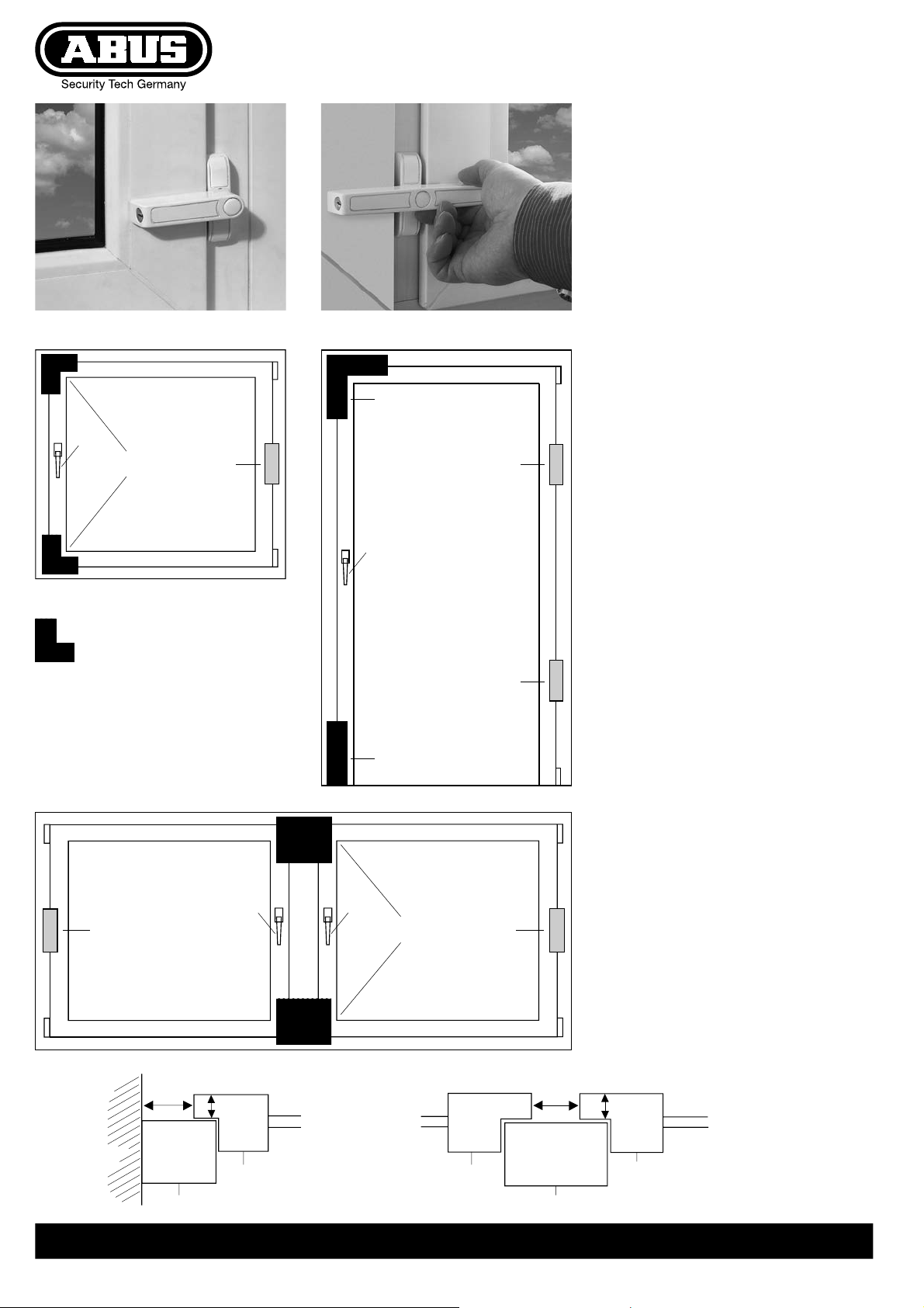
= D Montagebereich
= G fitting area
= F zone de fixation
= n montagezone
= I punto di fissaggio
Abb./ fig./schéma/ afb./ill. 1
FAS
D Diese Anleitung ist wie folgt untergliedert:
I. Allgemeine Hinweise IV. Werkzeug
II. Einsatzmöglichkeit V. Montageanleitung
III. Packungsinhalt VI. Bedienung
I. Allgemeine Hinweise
Die Fenstersicherungen 2510 und 2520 werden auf der Innenseite
der Fenster (Schlossseite/Griffseite) montiert und eignen sich für alle
gängigen nach innen öffnenden Fenster und Fenstertüren. Mit dieser
Montageanleitung können nicht alle Anwendungsmöglichkeiten für
ABUS 2510 und 2520 angesprochen werden. Fragen Sie ggf. auch
den Fachmann in Ihrer Nähe. Die optimale Schutzwirkung erreichen
Sie, wenn entsprechend dieser Montage- und Bedienungsanleitung
vorgegangen wird. Die Befestigungsschrauben sollten zur Vermeidung
von Überdrehung mit einem geeigneten Werkzeug von Hand angezogen werden. Für eventuell auftretende Verletzungen bzw. Schäden,
die bei der Montage und/oder durch unsachgemäße Handhabung
entstehen, übernimmt der Hersteller keine Haftung!
II. Einsatzmöglichkeit
ABUS 2510 eignet sich für alle nach innen öffnenden, einflügeligen
Fenster und Fenstertüren mit einer Falzstärke von 13 bis 20 mm,
DIN-rechts und DIN-links angeschlagen. ABUS 2520 eignet sich für
alle nach innen öffnenden zweiflügeligen Fenster und Fenstertüren
mit Mittelsteg und einem Flügelabstand von mind. 20 mm.
Die Fenstersicherungen werden ohne Schlüssel abgeschlossen
2510
FAS
FO
FAS
2510
FOFO
FAS2520FAS
= hoher Bedienkomfort.
Es ist grundsätzlich empfehlenswert, 2 Sicherungen auf der
Schlossseite und weitere Sicherungen (ABUS FAS 97 oder FAS 101)
auf der Bandseite zu montieren.
III. Packungsinhalt
• 1 St. Sicherung
• 1 Satz Kunststoffunterlagen
• 2 Schrauben 5,5 x 60 mm
IV. Montagewerkzeuge:
• Metermaß
• Kreuzschlitz-Schraubendreher
• Bohrmaschine (geeignet für 12 mm Bohrer)
• Metallbohrer 4 mm und 12 mm
V. Montageanleitung
Messen Sie bitte nach, ob die in Abb. 2 angegebenen Mindestmaße
an Ihrem Fenster/Ihrer Fenstertür eingehalten wurden.
Die Bohrtiefen bzw. die Schraubenlängen müssen auf die örtlichen
Gegebenheiten abgestimmt werden.
Das Austreten des Bohrers bzw. der Schrauben auf der Rückseite
vermeiden!
Ggf. mit Bohranschlag arbeiten, kürzere Schrauben beschaffen
oder die vorhandenen Schrauben kürzen.
Beim Bohren keine beweglichen Teile, Dichtungen oder Glasscheiben
verletzen.
Hinweis:
An Kunststoff-Fenstern ohne Metalleinlage erreichen Sie eine
hochbelastbare Befestigung für die Sicherungen mit ABUSBefestigungsset IM 100 (im Handel erhältlich). Aus diesem Grund
trägt der Sicherungsbolzen bereits zur Verkrallung ein Gewinde.
Montage:
1. Montageposition festlegen
2. Riegel querstellen. Schraubenabdeckungen von unten
aus der Anschraubleiste herausdrücken (Abb. 3).
3. Bohrung A anzeichnen (Abb. 4). Als Hilfsmittel dient eine
der Kunststoffunterlagen.
Bohrung A mit Bohrer 4 mm ca. 47 mm tief vorbohren und
12 mm 47 mm tief aufbohren.
Schloss mit Bolzen einstecken und Bohrungen B anzeichnen,
mit Bohrer 4 mm ca. 47 mm tief vorbohren.
Bei Kunststoff-Fenstern ohne Metalleinlage siehe Montage
des empfohlenen Zubehörs IM 100.
4. Sicherungen 2510 und 2520 soweit mit Kunststoff-Unterlage
unterfüttern, bis zwischen Fensterflügel und Riegel ein Spalt
von ca. 2 mm entsteht (Abb. 5).
5. Sicherung mit 2 Schrauben 5,5 x 60 mm durch die Löcher B
anschrauben.
6. Funktion der Sicherung und Bedienbarkeit des Fensters
überprüfen.
7. Die Schraubenabdeckungen aufdrücken (Abb. 6).
VI. Bedienung:
Zur Verriegelung den Riegel ohne Schlüssel bis zum Rastpunkt drehen.
Das Aufschließen und Entriegeln erfolgt mit dem Schlüssel.
Die Verriegelungsposition ist sofort erkennbar.
Hinweis:
Die Fenstersicherungen 2510 und 2520 können gleichschließend
mit vielen ABUS-Sicherheitsprodukten ausgestattet werden,
d.h. Sie schließen alle Sicherungen mit dem gleichen Schlüssel.
Abb./ fig.
schéma
afb./ ill. 2
Laibung
soffit
recouvrement
binnenwelving
soffitto
min.
20 mm
13–20
mm
Fensterflügel / sash / cadre / raamvleugel / intelaiatura
Fensterrahmen / window frame / chambranle / raamkozijn / chiambrana
einflügeliges Fenster
single-sash window
fenêtre à simple battant
enkelvleugelig raam
finestre a saliscendi semplici
ABUS - Das gute Gefühl der Sicherheit
D Technische Änderungen vorbehalten. Für Irrtümer und Druckfehler keine Haftung. ABUS © 2006
min.
20 mm
Mittelsteg / middle bar / battant central / tussenstuk / asta trasversale
13–20
mm
Fensterflügel / sash / cadre / raamvleugel / intelaiatura
zweiflügeliges Fenster
double-sash window
fenêtre à double battant
dubbelvleugelig raam
finestre a saliscendi doppi
www.abus.com
390243 5/06
Page 2
G Fitting and Operating Instructions
for ABUS Window Security Devices 2510 and 2520
F Instructions de montage pour verrou de fenêtre ABUS 2510 et 2520
G These instructions are organised in the following sections:
I. General instructions IV. Tools
II. Possible uses V. Installation instructions
III. Pack contents VI. Operation
I. General instructions
The window security devices 2510 and 2520 are fitted on the inside
of windows (lock side/handle side) and are suitable for all standard
windows and french windows that open inwards. These fitting
instructions cannot cover every single possible use for ABUS 2510 and
2520. If in doubt ask your local dealer. The best possible protection is
achieved if you proceed in accordance with these fitting and operating
instructions. The fastening screws should be tightened manually with
an appropriate tool to prevent excessive turning. The manufacturer
accepts no liability for any injuries or damage caused by fitting and/or
improper handling!
II. Possible uses
ABUS 2510 is suitable for all single-sash windows and french windows
that open inwards with a rebate thickness of 13 to 20 mm, DIN-right
and DIN-left mounted. ABUS 2520 is suitable for all double-sash
windows and french windows that open inwards with a middle bar
and a sash distance of at least 20 mm.
The window security devices are locked without a key
= maximum operating convenience.
On principle it is recommended that you fit 2 security devices on
the lock side and further security devices (ABUS FAS 97 or FAS 101)
on the hinge side.
III. Pack contents
• 1 security device
• 1 set of plastic bases
• 2 screws 5.5 x 60 mm
IV. Tools
• Metric tape measure
• Cross-tip screwdriver
• Hand-drill (suitable for 12 mm drill bit)
• Twist drill bits 4 Ø mm and 12 Ø mm
V. Installation instructions
Check by measuring whether your windows/french windows are of
the minimum sizes indicated in fig. 2.
The drilling depths/the screw lengths have to be adapted to the local
conditions.
Avoid the drill bit or screw protruding from the back.
If necessary work with a drill depth-stop, procure shorter screws or
shorten the screws provided.
Do not damage any movable parts, seals or panes when drilling.
Note:
On plastic windows with no metal inlay you can fasten the security
devices to make them highly resistant using the ABUS Fastening Set
IM 100 (available in the shops). This is why the security bolt already
has a thread for claw-like bolting.
Fitting:
1. Determine fitting position.
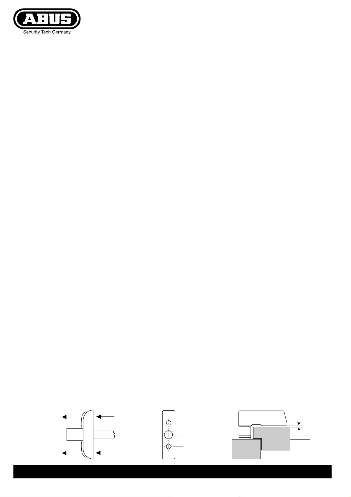
2. Place the bolt horizontally. Press the screw caps out of the
screw-down plate from below (fig 3.)
3. Mark drill hole A (fig. 4).
Use one of the plastic bases as an aid.
Pre-drill hole A about 47 mm deep with Ø 4 mm bit
and drill 47 mm deep with Ø 12 mm bit.
Insert lock with bolt and mark drill holes B,
pre-drill about 47 mm deep with Ø 4 mm bit.
For plastic windows with no metal inlay see fitting instructions
for the recommended accessory IM 100.
4. Underlay security devices 2510 and 2520 with plastic bases
until there is a gap of about 2 mm between the sash and the bolt
(fig. 5).
5. Screw on security device with 2 screws 5.5 x 60 mm through
holes B.
6. Check that the security device works and the window is operable.
7. Press the screw caps on (fig. 6).
VI. Operation
To lock the bolt without a key turn until the end point.
Use the key to unlock and unbolt. The locking position is immediately
recognisable.
Note:
Window Security Devices 2510 and 2520 can be equipped keyed-alike
with many ABUS security products, i.e. you lock all the security devices
with the same key.
F Ce manuel comporte les chapitres suivants:
I. Conseils d’ordre général IV. Outillage
II. Application V. Instructions d’installation
III. Liste de colisage VI. Utilisation
I. Conseils d’ordre général
Montez les dispositifs de sécurité pour fenêtres 2510 et 2520 sur le
côté donnant vers l’intérieur (côté fermeture/poignée). Les dispositifs
sont compatibles avec toutes les fenêtres classiques et portes-fenêtres
ouvrant vers l’intérieur. Les présentes instructions ne peuvent
s’appliquer à l’ensemble des utilisations possibles prévues par les
dispositifs ABUS 2510 et 2520. En cas de doute, veuillez contacter
votre revendeur. Pour une protection optimale, observez strictement
les instructions d’installation et d’utilisation. Les vis de fixation doivent
être vissées manuellement avec un outil approprié pour éviter un
serrage excessif. Le fabricant décline toute responsabilité en cas de
dommages ou de lésions corporelles dus à une installation non
conforme et/ou un usage détourné du dispositif.
II. Application
ABUS 2510 est compatible avec toutes les fenêtres simple battant
et portes-fenêtres ouvrant vers l’intérieur, avec une épaisseur de
feuillure entre 13 et 20 mm et tirant droite/gauche. ABUS 2520
est compatible avec toutes les fenêtres à double battant et portesbattant fenêtres ouvrant vers l’intérieur à battant central et un
écartement entre les cadres de 20 mm minimum.
Dispositifs de sécurité pour fenêtres avec système de verrouillage
sans clé = pour un confort d’utilisation optimal.
Il est recommandé de monter 2 dispositifs de sécurité côté serrure
et côté gonds (ABUS FAS 97 ou FAS 101).
III. Liste de colisage
• 1 dispositif de sécurité
• 1 jeu de cales en PVC
• 2 vis 5.5 x 60 mm
IV. Outillage
• Mètre ruban
• Tournevis cruciforme
• Perceuse (adapté pour trépans 12 mm)
• Forets métaux 4 Ø mm et 12 Ø mm
V. Instructions d’installation
Assurez-vous de la conformité des dimensions de vos fenêtres/portefenêtres par rapport aux dimensions minimums reportées schéma 2.
La profondeur de perçage/la longueur des vis doit être adaptée
en fonction des conditions particulières d’installation.
Veiller à ce que le trépan ou la vis ne ressorte pas à l’arrière.
Le cas échéant, utiliser une perceuse avec butée de profondeur
et se munir de vis plus courtes ou meuler les vis fournies en dotation.
Ne pas endommager les parties mobiles, joints d’étanchéité et
vitrages lors du perçage.
Note:
Sur les fenêtres en PVC sans armature métallique, il est possible de
renforcer la fixation du dispositif de sécurité avec le Kit de fixation
ABUS Set IM 100 (disponible chez votre revendeur), comme prévu par
le boulon de sécurité doté d’un filetage pour boulon à griffe.
Installation:
1. Déterminer la position
2. Positionnez le boulon horizontalement.
Oter les cache-vis de la plaque à visser en les poussant depuis
l’envers de la plaque (schéma 3.)
3. Prenez la marque du trou de forage A (schéma 4) à l’aide du
support en plastique.
Percez un avant-trou A d’une profondeur de 47 mm environ
à l’aide d’un trépan de 4 mm de diamètre et percez sur une
profondeur de 47 mm à l’aide d’un trépan de 12 mm de diamètre.
Insérez un pêne de serrure et prenez la marque du trou B
de forage. Percez un avant-trou d’une profondeur de 47 mm
environ à l’aide d’un trépan de 4 mm de diamètre.
Pour les fenêtres en PVC sans armature métallique,
observez les instructions pour l’accessoire recommandé IM 100.
4. Positionner les dispositifs de sécurité 2510 et 2520 à l’aide des
supports en plastique jusqu’à obtenir un espace d’environ 2 mm
entre le cadre et le boulon (schéma 5).
5. Visser le dispositif de sécurité dans le trou B au moyen de
2 vis 5,5 x 60 mm.
6. Assurez-vous du bon fonctionnement du dispositif de sécurité
et de la fenêtre.
7. Pressez sur les cache-vis (schéma 6).
VI. Utilisation
Pour bloquer le boulon sans clé, tourner jusqu’à résistance.
Pour déverrouiller et déboulonner, utiliser la clé.
La position verrouillage est immédiatement identifiable.
Note:
Les dispositifs de sécurité pour fenêtres 2510 et 2520 peuvent être
livrés avec des clés identiques compatibles avec de nombreux produits
ABUS pour verrouiller l’ensemble de vos dispositifs de sécurité avec
une seule et même clé.
Abb./ fig.
schéma
afb./ ill. 3
G Subject to technical alterations. No liability for mistakes and printing errors. ABUS © 2006
F Nous nous réservons le droit de toutes modifications techniques. Nous n’assumons aucune responsabilité pour des erreurs ou défauts d’impression éventuels. ABUS © 2006
Abb./ fig.
schéma
afb./ ill. 4
Abb./ fig.
schéma
B
A
B
afb./ ill. 5
2 mm
www.abus.com
390243 5/06
Page 3

n Montage- en gebruikshandleiding
voor de ABUS raambeveiligingen 2510 en 2520
I Istruzioni per l’uso Sistemi di sicurezza ABUS 2510 e 2520 per finestre
n Deze montage- en bedieningsinstructie is als volgt onderverdeeld:
I. Algemeen IV. Gereedschap
II. Toepassing V. Montage
III. Verpakkingsinhoud VI. Bediening
I. Algemeen
De raambeveiligingen 2510 en 2520 worden geïnstalleerd aan de
binnenkant van het raam (sluitzijde/handvatzijde) en passen op alle
naar binnen draaiende standaard ramen en glazen deuren. Deze
montagehandleiding omvat echter niet alle mogelijke toepassingen
van de ABUS 2510 en 2520. Bij twijfel neemt u best contact op met
uw plaatselijke verdeler. U realiseert de meest optimale beveiliging
wanneer u tewerk gaat zoals vermeld in deze montage- en
gebruikshandleiding. De bevestigingsschroeven moeten handmatig
vastgedraaid worden met een aangepast werktuig om te vermijden
dat ze al te vast zouden zitten. De fabrikant kan niet aansprakelijk
gesteld worden voor enig letsel of schade veroorzaakt bij de montage
en/of door een verkeerde manipulatie!
II. Toepassing
De ABUS 2510 is geschikt voor alle naar binnen draaiende enkelvleugelige ramen en glazen deuren met een sponningdikte van 13
tot 20 mm, DIN-rechts en DIN-links gemonteerd. De ABUS 2520 is
geschikt voor alle naar binnen draaiende dubbelvleugelige ramen
en glazen deuren met een tussenstuk en een vleugelafstand van
minstens 20 mm.
De raambeveiligingen worden vergrendeld zonder sleutel
= maximaal gebruikscomfort.
In principe raden we aan om 2 beveiligingen aan te brengen aan
de sluitzijde en bijkomende beveiligingen (ABUS FAS 97 of FAS 101)
aan de boordzijde.
III. Verpakkingsinhoud
• 1 beveiliging
• 1 set plastic steunen
• 2 schroeven 5,5 x 60 mm
IV. Gereedschap
• Meetlint
• Kruiskopschroevendraaier
• Handboor (geschikt voor boorijzer van 12 mm)
• Spiraalboorijzers diam. 4 mm en 12 mm
V. Montage
Meet na of uw ramen/glazen deuren de minimumafmetingen hebben
zoals vermeld in afb. 2.
De diepte van de boorgaten en de lengte van de schroeven moeten
aangepast worden aan de lokale omstandigheden.
Vermijd dat het boorijzer of de schroef er aan de achterkant uitkomen.
Gebruik indien nodig een booraanslag, kies voor kortere schroeven
of maak de beschikbare schroeven korter.
Zorg er bij het boren voor dat u geen bewegende delen,
dichtingen of ruiten beschadigt.
Opmerking:
Bij kunststof ramen zonder metalen inlegwerk kunt u de beveiligingen
nog duurzamer bevestigen door gebruik te maken van de ABUS
IM 100 bevestigingsset (verkrijgbaar in de handel). Daarom beschikt
de veiligheidsbout ook al over een schroefdraad om ze stevig vast
te zetten.
Montage:
1. Bepaal de montagepositie.
2. Plaats de schuifbout horizontaal.
Druk de dopmoeren van onderaf uit de schroeflijst (afb. 3)
3. Markeer het boorgat A (afb. 4).
Gebruik daartoe één van de plastic steunen.
Maak eerst een boorgat A van ca. 47 mm diep met het boorijzer
diam. 4 mm en boor dit gat vervolgens uit met het boorijzer
diam. 12 mm tot op een diepte van 47 mm.
Steek het slot met de bouten erin en markeer vervolgens de boorgaten B die u eerst voorboort tot op 47 mm diep met het boorijzer
diam. 4 mm.
Bij kunststof ramen zonder metalen inlegwerk:
zie montage-instructies voor het aanbevolen accessoire IM 100.
4. Leg plastic steunen onder de beveiligingen 2510 en 2520
tot er een spleet van ca. 2 mm is tussen de raamvleugel en de
schuifbout (afb. 5).
5. Schroef de beveiliging vast met behulp van 2 schroeven
5,5 x 60 mm door de boorgaten B.
6. Controleer of de beveiliging werkt en het venster geopend kan
worden.
7. Breng de dopmoeren opnieuw aan (afb. 6).
VI. Bediening
Om te vergrendelen draait u de schuifbout zonder sleutel naar
het eindpunt. Gebruik de sleutel om te ontgrendelen.
De vergrendelstand is onmiddellijk herkenbaar.
Opmerking:
De raambeveiligingen 2510 en 2520 kunnen
uitgerust worden met heel wat ABUS-beveiligingsproducten met centrale vergrendeling, m.a.w. alle
beveiligingen kunnen met éénzelfde sleutel
vergrendeld worden.
I Queste istruzioni si suddividono nel modo seguente:
I. Istruzioni generali IV. Attrezzi
II. Possibilità d’impiego V. Istruzioni di montaggio
III. Contenuto della confezione VI. Uso
I. Istruzioni generali
Installare i sistemi di sicurezza per finestre 2510 e 2520 sul lato
interno delle finestre (lato serratura/maniglia). I sistemi di sicurezza
sono compatibili con tutti i modelli standard di finestre e portefinestre
con apertura verso l’interno. Le presenti istruzioni non possono contemplare tutte le applicazioni possibili previste dai dispositivi ABUS
2510 e 2520. In caso di dubbio, rivolgersi al rivenditore di fiducia.
Al fine di garantire una maggiore protezione, si raccomanda di seguire
attentamente le presenti istruzioni per il montaggio e l’uso dei sistemi
di sicurezza. Le viti di fissaggio devono essere avvitate manualmente
con un apposito attrezzo in modo da evitare un serraggio eccessivo.
Il costruttore declina ogni responsabilità per danni a persone o cose
derivante da inadeguata istallazione e/o uso improprio del dispositivo.
II. Possibilità d’impiego
ABUS 2510 è compatibile con tutte le finestre a saliscendi semplici e
portefinestre con apertura verso l’interno, con uno spessore di battuta
da 13 a 20 mm, e apertura destra/sinistra. ABUS 2520 è compatibile
con tutte le finestre a saliscendi doppi e portefinestre con apertura
verso l’interno, con asta trasversale e distanza tra intelaiature pari
a 20 mm min.
Sistemi di sicurezza per finestre con sistema di chiusura senza chiave
= per un maggior comfort di utilizzo.
Si consiglia di installare 2 sistemi di sicurezza sul lato serratura e
ulteriori dispositivi (ABUS FAS 97 ou FAS 101) sul lato chiambrana.
III. Contenuto della confezione
• 1 sistema di sicurezza
• 1 kit con supporti in plastica
• 2 viti 5,5 x 60 mm
IV. Attrezzi
• Metro a nastro
• Cacciavite con punta a croce
• Martello perforatore (adatto per scalpelli 12 mm)
• Punte elicoidali 4 Ø mm e 12 Ø mm
V. Istruzioni di montaggio
Assicurarsi della conformità delle dimensioni delle vostre finestre/
portefinestre con le dimensioni minime riportate nella ill. 2.
La profondità di perforazione/la lunghezza delle viti deve essere
regolata secondo le particolari condizioni di istallazione.
Evitare che il trapano o la vite fuoriescano sul retro.
Qualora fosse necessario, utilizzare un martello perforatore con
asta di profondità e viti più corte oppure ridurre la lunghezza delle
viti incluse nella confezione.
Non danneggiare le parti mobili, le guarnizioni di tenute,
o i vetri durante la foratura.
Nota:
E’ possibile rafforzare il fissaggio del sistema di sicurezza sulle finestre
en PVC sprovviste di armatura metallica, mediante il Kit di fissaggio
ABUS Set IM 100 (disponibile presso il vostro rivenditore),
come previsto dal bullone di sicurezza munito di filettatura.
Istallazione:
1. Delimitare il punto di fissaggio.
2. Posizionare il bullone in modo orizzontale. Rimuovere i tappi
filettati dalla placca da avvitare spingendoli dal retro (vedi ill. 3.).
3. Marcare la posizione del foro A (vedi ill. 4) mediante un supporto
in plastica.
Praticare un foro guida A di 47 mm circa di profondità mediante
un trapano di 4 mm de diametro e forare sino a raggiungere
una profondità pari a 47 mm mediante un trapano di 12 mm
di diametro.
Inserire un chiavistello e marcare la posizione del foro B.
Praticare un foro guida di 47 mm circa di profondità mediante
un trapano di 4 mm de diametro.
Per le finestre in PVC sprovviste di armatura metallica,
osservare le istruzioni relative all’accessorio consigliato IM 100.
4. Posizionare i sistemi di sicurezza 2510 e 2520 mediante i
supporti di plastica, fino a ottenere uno spazio di circa 2 mm
tra l’intelaiatura e il bullone (vedi ill. 5).
5. Fissare il sistema di sicurezza nel foro B mediante 2 viti
5,5 x 60 mm.
6. Assicurarsi del buon funzionamento del sistema di sicurezza
e della finestra.
7. Premere sui tappi filettati (ill. 6).
VI. Uso
Per bloccare il bullone senza chiave, ruotare fino a fine corsa.
Per sbloccare e sbullonare, utilizzare la chiave.
La posizione chiusura è immediatamente identificabile.
Nota:
I dispositivi di sicurezza per finestre 2510 e 2520 possono essere
dotati di sistemi di chiusura identici che consentono di adottare
un’unica chiave compatibile con numerosi prodotti ABUS.
Abb./ fig.
schéma
afb./ ill. 6
n Technische wijzigingen voorbehouden. Geen aansprakelijkheid voor vergissingen en drukfouten. ABUS © 2006
I Ci si riservano modifiche tecniche. Per errori e refusi di stampa non ci si assume alcuna responsabilità. ABUS © 2006
www.abus.com
390243 5/06
 Loading...