

Abstrakt instruments Avalon User Manual
REFERENCE MANUAL
v1.07a
September 2019
Information contained in this manual is subject to change
without notice. No part of this manual may be reproduced
or transmitted in any form, or by any purpose other than the
purchaser's personal use, without the express written
consent of Abstrakt Instruments LLC.
All other product and company names used in this manual
are trademarks or registered trademarks of their respective
owners.
© 2019 Abstrakt Instruments
www.abstraktinstruments.com
2 AVALON - Reference Manual

Read all instructions below and follow them.
IMPORTANT SAFETY AND MAINTENANCE INSTRUCTIONS
1. Do not use this product near water - for example, in the rain, near a bathtub or sink, in a wet basement, or near a
swimming pool or the like.
2. This product, in combination with an amplifier and headphones or speakers, may be capable of producing sound levels
that could cause permanent hearing loss. Do not operate for a long period of time at a high volume level or at a level that is
uncomfortable.
3. Never use aggressive cleaners on the casing. Remove dust, dirt, and fingerprints with a soft, dry, non-abrasive cloth. If the
unit is persistently dirty use a slightly damp cloth using only water. Do not use a liquid cleaner, alcohol, acetone,
turpentine, or any other organic solutions.
4. Install in accordance with the instructions. Make sure you place the unit on a stable surface before use.
5. The product should be located away from heat sources such as radiators, heat registers, or other products that produce
heat.
6. Connect the unit to an easily accessible electrical outlet that is close to it.
7. The product should be connected to a power supply only of the type described in the operating instructions or as
marked on the product.
8. Unplug the unit during lightning storms or when it is not used for long periods of time.
9. Care should be taken so that objects do not fall and liquids are not spilled into the enclosure through openings.
10. When transporting the unit, use accessories recommended by the manufacturer or the original box and padding.
11. Abstrakt Instruments is not responsible for any damage caused by improper operation of the instrument.
WARNING
To reduce the risk of fire, electrical shock or product damage:
Do not expose the unit to rain, moisture, dripping or splashing. Also avoid placing objects filled with liquid, such as vases, on the unit.
Do not expose the unit to direct sunlight, nor use it in ambient temperatures exceeding 30°C as this can lead to malfunction.
Do not open the casing. There are no user repairable or adjustable parts inside. Leave service and repairs to trained service technicians only.
EXTERNAL POWER SUPPLY SAFETY INSTRUCTIONS
The adapter is not safety grounded and may only be used indoors.
To ensure good ventilation for the adapter, do not place it in tight spaces. To prevent risk of electric shock and fire because of over-heating,
ensure that curtains and other objects do not prevent adapter ventilation.
Do not expose the power adapter to direct sunlight, nor use it in ambient temperatures exceeding 40°C.
In the EU, only use CE approved power cords.
3 AVALON - Reference Manual

This equipment has been tested and found to comply with the limits for a Class B digital device,
pursuant to part 15 of the FCC Rules. These limits are designed to provide reasonable protection
against harmful interference in a residential installation. This equipment generates, uses and can
radiate radio frequency energy and, if not installed and used in accordance with the instructions, may
cause harmful interference to radio communications. However, there is no guarantee that interference
will not occur in a particular installation. If this equipment does cause harmful interference to radio or
television reception, which can be determined by turning the equipment off and on, the user is
encouraged to try to correct the interference by one or more of the following measures:
Reorient or relocate the receiving antenna.
Increase the separation between the equipment and receiver.
Connect the equipment into an outlet on a circuit different from that to which the receiver is
connected.
Consult the dealer or an experienced radio/TV technician for help.
This Class B digital apparatus meets all requirements of the Canadian Interference-Causing
Equipment Regulation.
Cet appareil numérique de la classe B respecte toutes les exigences du Règlement sur le matériel
brouilleur du Canada.
This product has been tested to comply with the Low Voltage Directive 2006/95/EC and the
Electromagnetic Compatibility Directive 2004/108/EC. The product meets the requirements of RoHS 2
Directive 2011/65/EU.
This symbol indicates that your product must be disposed of properly according to local laws and
regulations.
European Union regulation compliance statement
4 AVALON - Reference Manual

CONTENTS
1 INTRODUCTION ............................................................................. 7
1.1 ABOUT THIS MANUAL ....................................................................... 7
1.2 ABBREVIATION & CONVENTIONS ................................................ 7
1.2.1 BUTTON NAMES ........................................................................ 7
1.2.2 BUTTON COMBINATIONS (SIMULTANEOUS) ............... 7
1.2.3 STEP BUTTONS .......................................................................... 7
1.2.4 CHROMATIC KEYBOARD ....................................................... 7
1.2.5 PATTERN BUTTONS ................................................................. 7
1.2.6 BUTTONS 1-4 ............................................................................. 7
1.2.7 NOTE, TIE, & REST BUTTONS ............................................... 8
1.2.8 NEXT & BACK BUTTONS ......................................................... 8
1.2.9 ROTARY KNOBS ......................................................................... 8
1.2.10 LED INDICATORS ..................................................................... 8
2 OVERVIEW ..................................................................................... 9
2.1 FRONT PANEL ......................................................................................... 9
2.2 REAR PANEL ......................................................................................... 10
2.3 INITIAL CONNECTIONS .................................................................... 10
3 ANALOG SYNTH .......................................................................... 11
3.1 ZERO THE SYNTHESIZER ................................................................. 11
3.2 OSCILLATOR......................................................................................... 11
3.3 FILTER ..................................................................................................... 11
3.4 FILTER ENVELOPE .............................................................................. 12
3.5 AMPLIFIER ............................................................................................. 12
3.6 MODULATION ENVELOPE .............................................................. 12
3.7 OUTPUT ................................................................................................. 12
4 SEQUENCER OVERVIEW .............................................................. 13
4.1 PRIMARY MODES ............................................................................... 13
4.1.1 CHANGING PRIMARY MODES ............................................ 13
4.1.1.1 BETWEEN PATTERN MODES .................................... 13
4.1.1.2 BETWEEN TRACK MODES .......................................... 13
4.1.1.3 BETWEEN PATTERN & TRACK MODES ................. 13
4.2 WHAT IS A PATTERN? ...................................................................... 13
4.2.1 THE PATTERN STEP ................................................................. 13
4.2.2 PATTERN STEP ATTRIBUTES ............................................... 13
4.2.3 PATTERN MODIFIERS ............................................................. 13
4.2.4 PATTERN OVERALL STRUCTURE ....................................... 14
4.3 PATTERN SELECTION ........................................................................ 14
4.3.1 PATTERN BANK ......................................................................... 14
4.3.2 PATTERN GROUP ..................................................................... 14
4.3.3 PATTERN NUMBER .................................................................. 14
4.4 PATTERN PLAYBACK ......................................................................... 14
4.4.1 TEMPO .......................................................................................... 14
4.5 WHAT IS A TRACK? ............................................................................ 15
4.6 TRACK SELECTION ............................................................................. 15
4.7 TRACK PLAYBACK .............................................................................. 15
5 PATTERN WRITE MO .................................................................... 16
5.1 OVERVIEW.............................................................................................. 16
5.2 NORMAL MODE ................................................................................... 16
5.2.1 PATTERN CLEAR, COPY & PASTE ...................................... 16
5.2.2 PATTERN CHAINING ............................................................... 17
5.2.3 PATTERN MODIFIERS ............................................................. 17
6) Pattern Direction ....................................................................... 17
5.2.3.1 PATTERN LENGTH ........................................................ 17
5.2.3.2 LAST STEP ........................................................................ 17
5.2.3.3 COPY PATTERN SECTION ........................................... 17
5.2.3.4 TIME SIGNATURE .......................................................... 17
5.2.3.5 SHUFFLE ........................................................................... 18
5.2.3.6 PATTERN DIRECTION .................................................. 18
5.2.3.7 PATTERN ROTATE ......................................................... 18
5.2.3.8 PATTERN RANDOMIZE .............................................. 18
5.2.3.9 PATTERN TRANSPOSE ................................................ 18
5.2.3.10 FILTER B MODE .......................................................... 18
5.2.3.11 SCREENSAVER MODE (LOW NOISE) .................. 18
5.2.4 PITCH ATTRIBUTES ................................................................. 19
5.2.4.1 PITCH ................................................................................. 19
5.2.4.2 ACCENT & SLIDE ............................................................ 19
5.2.4.3 TRANSPOSE..................................................................... 19
5.2.4.4 MODULATION ENVELOPE TRIGGERS ................. 19
5.2.4.5 SLIDE TIME....................................................................... 19
5.2.4.6 FILTER CV OFFSET ........................................................ 19
5.2.4.7 GATE LENGTH ................................................................ 20
5.2.5 TIME ATTRIBUTES .................................................................. 20
5.2.5.1 NOTE EVENTS ................................................................ 20
5.2.5.2 NOTE LENGTH, TIES & RESTS ................................. 20
5.2.5.3 ACTIVE STEPS ................................................................ 20
5.3 PITCH & TIME STEP ENTRY MODES ............................................ 21
5.3.1 PITCH STEP ENTRY ................................................................. 21
5.3.2 TIME STEP ENTRY ................................................................... 21
5.4 RECORD MODE ................................................................................... 21
5.4.1 ENTER & EXIT RECORD MODE ............................................. 21
5.4.2 RECORDING REALTIME PERFORMANCE ........................ 21
5.4.2.2 RECORD TRANSPOSE ................................................. 22
5.4.2.3 RECORD ACCENT & SLIDE ........................................ 22
5.4.2.4 RECORD MOD ENV ...................................................... 22
5.4.2.5 RECORD SLIDE TIME ................................................... 22
5.4.2.6 RECORD FILTER CV OFFSET .................................... 22
5.5.1 REALTIME ACCENT & SLIDE ............................................... 22
5.5.2 REALTIME MOD ENV .............................................................. 22
5.6 ARPEGGIATOR ..................................................................................... 23
5.6.1 ARP ON/OFF ............................................................................... 23
5.6.2 NOTE ENTRY .............................................................................. 23
5.6.2.1 VIA AVALON KEYBOARD........................................... 23
5.6.2.2 VIA EXTERNAL MIDI .................................................... 23
5.6.3 ARP MODE .................................................................................. 23
5.6.4 REALTIME ACCENT, SLIDE, & MOD ENV ........................ 23
5.6.5 ARP RECORD .............................................................................. 23
5.7 PATTERN SYSEX DUMP .................................................................... 23
5.7.1 TRANSMIT ................................................................................... 23
5.7.2 RECEIVE ........................................................................................ 23
6 PATTERN PLAY MODE ................................................................ 24
6.1 OVERVIEW ............................................................................................. 24
6.2 NORMAL MODE ................................................................................... 24
6.2.1 PATTERN SELECTION ............................................................. 24
6.2.2 PATTERN CHAINING ............................................................... 24
6.3 REALTIME MODE ................................................................................. 24
6.3.1 TRANSPOSE ............................................................................... 24
6.3.2 REALTIME ACCENT & SLIDE ............................................... 25
6.3.3 REALTIME MOD ENV .............................................................. 25
6.3.4 REALTIME MUTE ..................................................................... 25
7 TRACK WRITE MODE ................................................................... 26
7.1 OVERVIEW ............................................................................................. 26
7.2 SELECTING TRACKS ........................................................................... 26
7.3 NORMAL MODE ................................................................................... 26
7.3.1 TRACK STEP INDICATORS .................................................... 26
7.3.2 LAST TRACK STEP .................................................................... 26
7.3.3 TRACK CLEAR, COPY & PASTE ........................................... 27
7.3.4 WRITING A TRACK ................................................................... 27
7.3.4.1 SELECT PATTERN .......................................................... 27
7.3.4.2 TRANSPOSE..................................................................... 27
7.3.4.3 ADD REPEATS................................................................. 27
7.3.4.4 PREVIOUS & NEXT STEP............................................. 27
7.3.4.5 LAST STEP ........................................................................ 28
5 AVALON - Reference Manual

7.4 REALTIME MODE ................................................................................. 28
7.4.1 REALTIME ACCENT & SLIDE ............................................... 28
7.4.2 REALTIME MOD ENV .............................................................. 28
7.4.3 REALTIME MUTE ...................................................................... 29
7.5 TRACK SYSEX DUMP ......................................................................... 29
7.5.1 TRANSMIT ................................................................................... 29
7.5.2 RECEIVE ........................................................................................ 29
8 TRACK PLAY MODE ...................................................................... 30
8.1 OVERVIEW.............................................................................................. 30
8.2 SELECTING TRACKS ........................................................................... 30
8.3 NORMAL MODE ................................................................................... 30
8.3.1 TRACK STEP INDICATORS .................................................... 30
8.4 REALTIME MODE ................................................................................. 30
8.4.1 REALTIME ACCENT & SLIDE ............................................... 30
8.4.2 REALTIME MOD ENV .............................................................. 30
8.4.3 REALTIME MUTE ...................................................................... 30
9 MIDI PLAY .................................................................................... 31
9.1 STOP THE SEQUENCER ..................................................................... 31
9.2 SET MIDI INPUT CHANNEL .............................................................. 31
9.3 DISABLE MIDI SYNC ........................................................................... 31
9.4 MIDI RECEIVE PARAMETERS .......................................................... 31
9.4.1 NOTE ON / ACCENT/ SLIDE .................................................. 31
9.4.2 FILTER CUTOFF ......................................................................... 31
9.4.3 MODULATION ENVELOPE TRIGGER ................................ 31
10 CONFIGURATION MODE ........................................................... 32
10.1 ENTER CONFIG MODE ..................................................................... 32
10.1.1 SYNC INPUT ............................................................................. 32
10.1.1.1 MIDI SYNC IN BEHAVIOR ........................................ 32
10.1.2 SYNC OUTPUT ....................................................................... 32
10.1.3 MIDI INPUT CHANNEL ......................................................... 32
10.1. 4 MIDI OUTPUT CHANNEL ................................................... 32
10.1.5 USB MIDI ................................................................................... 32
10.1.6 LED DIMMING ........................................................................ 32
10.1.7 DUMP MACHINE STATE .................................................... 32
10.1.8 DUMP PATTERN BANK ...................................................... 33
10.1.8.1 PATTERN BANK SEND .............................................. 33
10.1.8.2 PATTERN BANK RECEIVE ......................................... 33
10.1.9 MIDI PROGRAM CHANGE ................................................. 33
10.1.10 OS VERSION .......................................................................... 33
10.2 EXIT CONFIG MODE ......................................................................... 33
11 INPUTS & OUTPUTS .................................................................. 34
11.1 AUDIO I/O ........................................................................................... 34
11.2 CV & GATE I/O ................................................................................... 34
12 SPECIFICATIONS ....................................................................... 35
13 TB-303 SETTINGS ...................................................................... 36
13.1 ANALOG VOICE ................................................................................. 36
13.1.1 OSCILLATORS ......................................................................... 36
13.1.2 FILTER ........................................................................................ 36
13.1.3 FILTER ENVELOPE .................................................................. 36
13.1.4 VCA ENVELOPE ...................................................................... 36
13.1.5 MODULATION ENVELOPE ................................................. 36
13.2 SEQUENCER ........................................................................................ 36
13.2.1 PATTERN WRITE MODES.................................................... 36
13.2.2 PATTERN MODIFIERS .......................................................... 36
13.2.3 PATTERN STEP ATTRIBUTES ............................................ 36
14 BLOCK DIAGRAM ...................................................................... 36
APPENDIX A - CALIBRATION .......................................................... 38
APPENDIX B - FILTER & VCA BEHAVIOR ....................................... 40
APPENDIX C - AVALON VS. TB-303 SEQUENCER ......................... 44
APPENDIX D - MIDI IMPLEMENTATION ........................................ 45
6 AVALON - Reference Manual
1 INTRODUCTION
Thank You for purchasing the Avalon Bassline Synthesizer! The
Avalon is a powerful synth and sequencer designed to be equally at
home in the studio or in live performance.
Be sure to visit www.abstraktinstruments.com for the latest firmware
and tutorials.
1.1 ABOUT THIS MANUAL
This manual was written to help familiarize you with Avalon
synthesizer. There are a lot of features packed into the Avalon, we
recommend reading this manual in its entirety.
1.2 ABBREVIATION & CONVENTIONS
Additional info on a given topic.
Tips to simplify specific topics.
1.2.1 BUTTON NAMES
Button names are illustrated in bold uppercase. For example, the
button labeled "home" is written HOME. Buttons that are specific to
"pitch", "time" or secondary "functions" are typed in color-coded
brackets, such as [PITCH], [TIME] and [FUNCTION].
1.2.2 BUTTON COMBINATIONS (SIMULTANEOUS)
Whenever multiple buttons are to be pressed simultaneously the "+"
sign is used. The first button name is the first button pressed. The
second button name after the "+" sign is the second button pressed
(while holding the first button). In some cases there are additional
button presses.
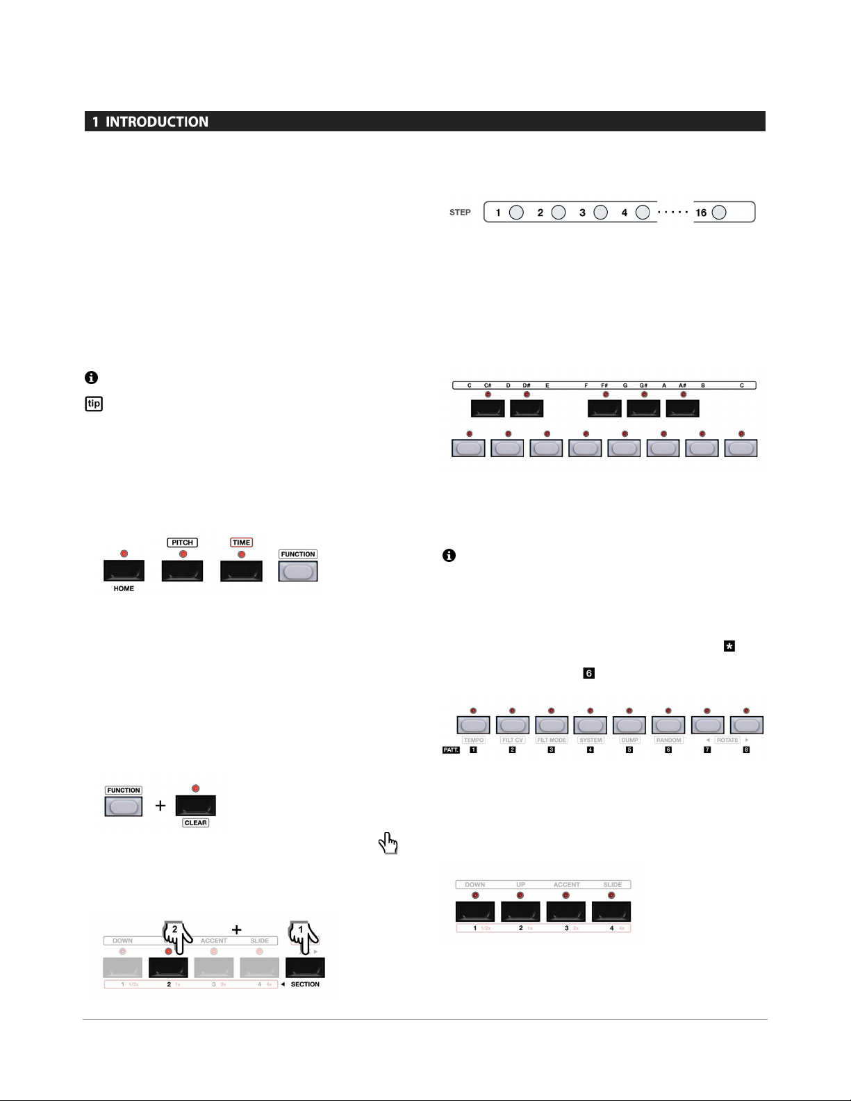
For example, to clear a pattern the "function" and "clear" buttons are
pressed in order as shown below. This would be written as
[FUNCTION] + [CLEAR], and illustrated as shown below:
In some instances button combinations are indicated using the
"finger point" graphic. In these instances the order of button presses
is indicated by the number of each hand. For example, SECTION +
BUTTON 2 is equivalent to the graphic below.
1.2.3 STEP BUTTONS
The (16) step button indicators are used for entering various step
attributes. They are also used for certain secondary functions such as
setting MIDI channels and Sync modes. The step buttons will be
abbreviated as STEP BUTTON * in bold font where "*" denotes the
step number. For example "step button 4" would be denoted STEP
BUTTON 4.
1.2.4 CHROMATIC KEYBOARD
The buttons that make up the one octave keyboard are used for
multiple functions. Whenever they are used for pitch (note) entry the
buttons will denoted by [BUTTON KEY *] in bold font. For example,
when referring to the "C#" key it would be written [BUTTON KEY C#].
The upper C is denoted [BUTTON KEY C'].
1.2.5 PATTERN BUTTONS
The "white" keys of the chromatic keyboard are used for pattern
selection. Whenever the pattern 1-8 buttons are used in reference to
pattern selection they will be denoted by PATTERN BUTTON in
bold font. For example, when referring to pattern 6 it would be
written as PATTERN BUTTON .
1.2.6 BUTTONS 1-4
The black buttons labeled 1-4 are used for various duties such as
selecting pattern sections, pattern time signature, and for setting
gate lengths and slide times per step.
When these buttons are referenced they are written BUTTON 1,
BUTTON 2, BUTTON 3, & BUTTON 4. When referred to as a group
7 AVALON - Reference Manual
they are written BUTTON 1-4.
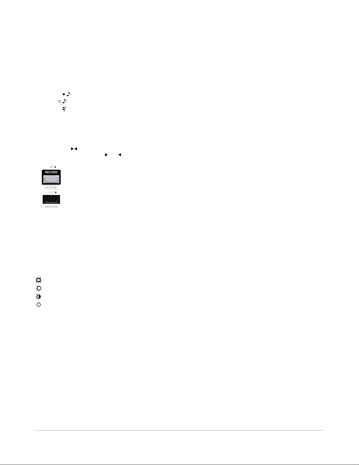
1.2.7 NOTE, TIE, & REST BUTTONS
The note, tie and rest buttons are indicated by musical notation on
the control surface of the Avalon. When used in this manual these
buttons will be written NOTE, TIE and REST.
NOTE = (16th note symbol)
TIE = (16th tie symbol)
REST = (16th rest symbol)
1.2.8 NEXT & BACK BUTTONS
The Avalon has NEXT and BACK operations that are used in some
modes. These buttons are not labeled with text, but rather with
direction arrows ( ) as shown below. When used in this manual
these buttons will be written NEXT and BACK.
1.2.9 ROTARY KNOBS
Rotary knob names are shown in uppercase bold italic. For example
the "tune" control would be written as TUNE.
1.2.10 LED INDICATORS
LED states are illustrated below.
Fully Lit
Dimly Lit
Blinking
Off
LED indicators are illustrated by their function. This usually
corresponds to the button text above or below the LED. For example,
the accent led above the accent button would be written as [ACCENT
LED].
8 AVALON - Reference Manual
2 OVERVIEW
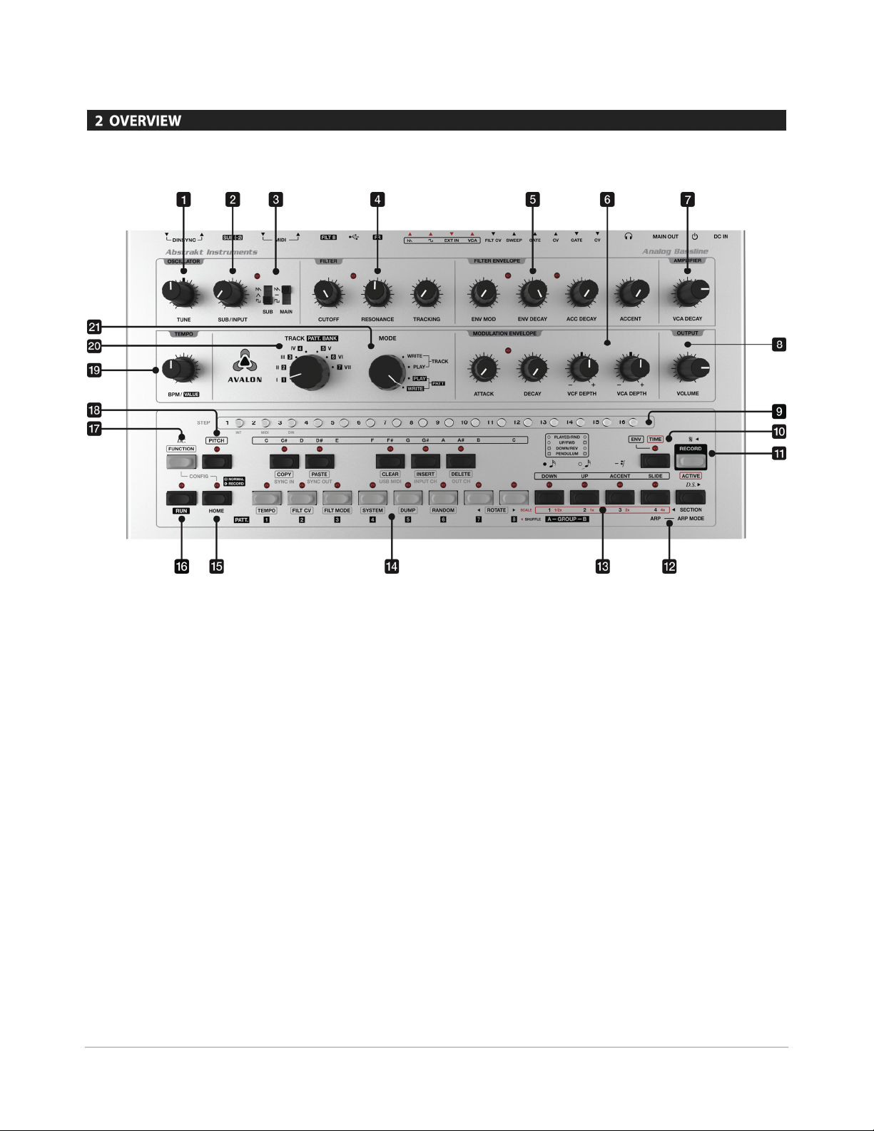
2.1 FRONT PANEL
[1] TUNE control sets the master tune of the oscillators.
[2] SUB/INPUT sets the level of the sub oscillator or
external input.
[3] WAVEFORM switches select the waveshape for the main
and sub oscillators. The main oscillator can be selected between
saw, square and off. The sub oscillator can be selected between
saw, triangle, and square waveforms.
[4] FILTER controls are used to set the cutoff, resonance
and key tracking amounts.
[5] FILTER ENVELOPE controls are used for setting the filter
envelope decay times, modulation depth, and accent amount.
[6] MODULATION ENVELOPE controls are used for setting the
attack and decay times of the modulation envelope and for
setting the modulation depth to the filter and final amplifier.
[7] VCA DECAY sets the decay time of the VCA envelope.
[8] VOLUME sets the output level to the main output and
headphones.
[9] STEP BUTTONS are used to select and display sequence step
parameters.
[10] TIME is used to enter TIME related parameters and for entering
TIME ENTRY mode for step input.
[11] RECORD is used to record realtime performance into a
sequence.
[12] ARP - ARP MODE are used for enabling the arpeggiator and
setting the arp direction.
[13] BUTTONS 1-4 are used when selecting parameters such
as such as pattern sections, time signatures, pattern & arp
directions, and various pitch and time step attributes.
[14] KEYBOARD is used for selecting the pitch of notes. The white
keys together with the GROUP A/B buttons and PATT. BANK
selector are also used for pattern selection.
[15] HOME is used to return the sequencer back to NORMAL MODE
for each primary mode.
[16] RUN is used to start and stop the sequencer.
[17] FUNCTION is used when selecting various alternate functions.
[18] PITCH is used to enter PITCH related parameters and for
entering PITCH ENTRY mode for step input.
[19] TEMPO sets the bpm of the sequencer when using internal sync.
TRACK / PATT. BANK selects the current track or pattern bank.
[20]
9 AVALON - Reference Manual
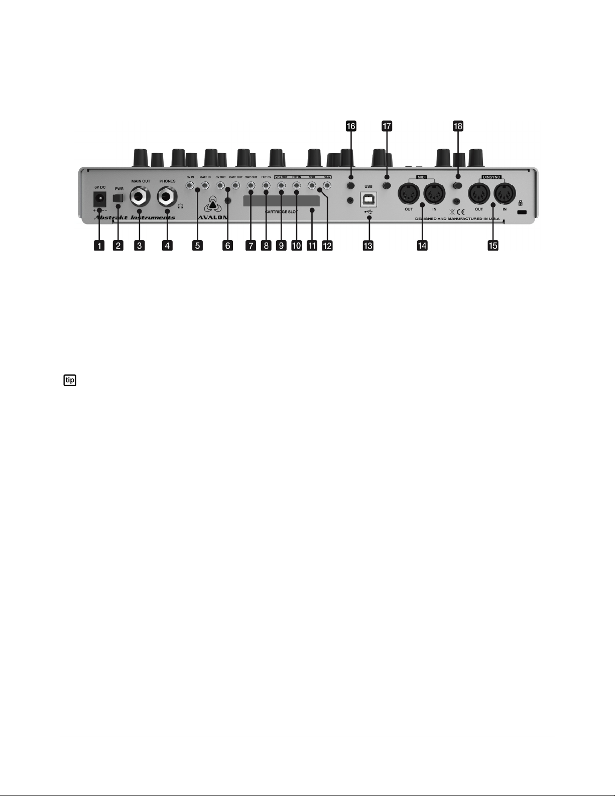
2.2 REAR PANEL
[21] MODE selects the sequencer primary mode.
[1] DC POWER connector for connecting the external 6VDC PSU.
[2] PWR switch for turning the machine on and off.
[3] MAIN OUT is a 1/4" unbalanced jack for connecting the main
output to the sound system.
Make all audio connections before you turn on the power to
your audio mixer or amplifier. Turn on the power of your
powered speaker or amplifier last. Turn off the power of your
powered speaker or amplifier first.
[4] PHONES is a stereo 1/4" output jack for connecting
headphones.
[5] CV & GATE IN are 1/8" mono jacks used for controlling the
Avalon keyboard CV and filter/amp envelope gating from
external analog gear.
[6] CV & GATE OUT are 1/8" mono jacks that output sequencer
pitch CV and gate. The CV output is 1V/Oct and the range is 0V
to 5V. The gate output is a 0-12V V-trigger.
[7] SWP OUT is a normalized copy of the accent sweep control
voltage that is derived on accented notes. The output is 0V to
5V max.
[8] FILT CV accepts a CV input for controlling filter cutoff frequency.
The response is 1V/Oct. The useful range is 0-5V.
[9] VCA OUT is the output signal from the VCA.
[10] EXT IN is an audio input to the filter. It accepts a wide range of
signal levels as it has an internal preamp stage. When the
external input is used the sub oscillator is bypassed.
[11] CARTRIDGE SLOT is used for optional filter cartridges.
[12] SAW and SQR are +/-5V buffered outputs from the oscillator.
[13] USB class compliant port for connection to a PC or Mac.
[14] MIDI jacks for MIDI input & output.
[15] DINSYNC jacks for DINSync input & output.
[16] FR selects the low frequency response of the audio between
normal and extended range. Normal range is -6dB @ 70Hz.
Extended range is -6dB @ 30Hz.
[17] FILT B selects between the internal filter and a filter cartridge.
When the switch is pushed in (enabled) the filter cart is
selected. If FILT B is selected and there is no filter cartridge
inserted there will be no audio output from the synth.
[18] SUB (-2) selects the octave of the sub oscillator between (-1)
and (-2) octave. When the switch is pushed in (-2) octaves is
selected.
2.3 INITIAL CONNECTIONS
AUDIO OUTPUTS. To hear the audio output from the synth you
will need to use headphones or connect the main output to your
sound system.
POWER. Turn on the unit. The step indicators will splash a startup
pattern.
10 AVALON - Reference Manual
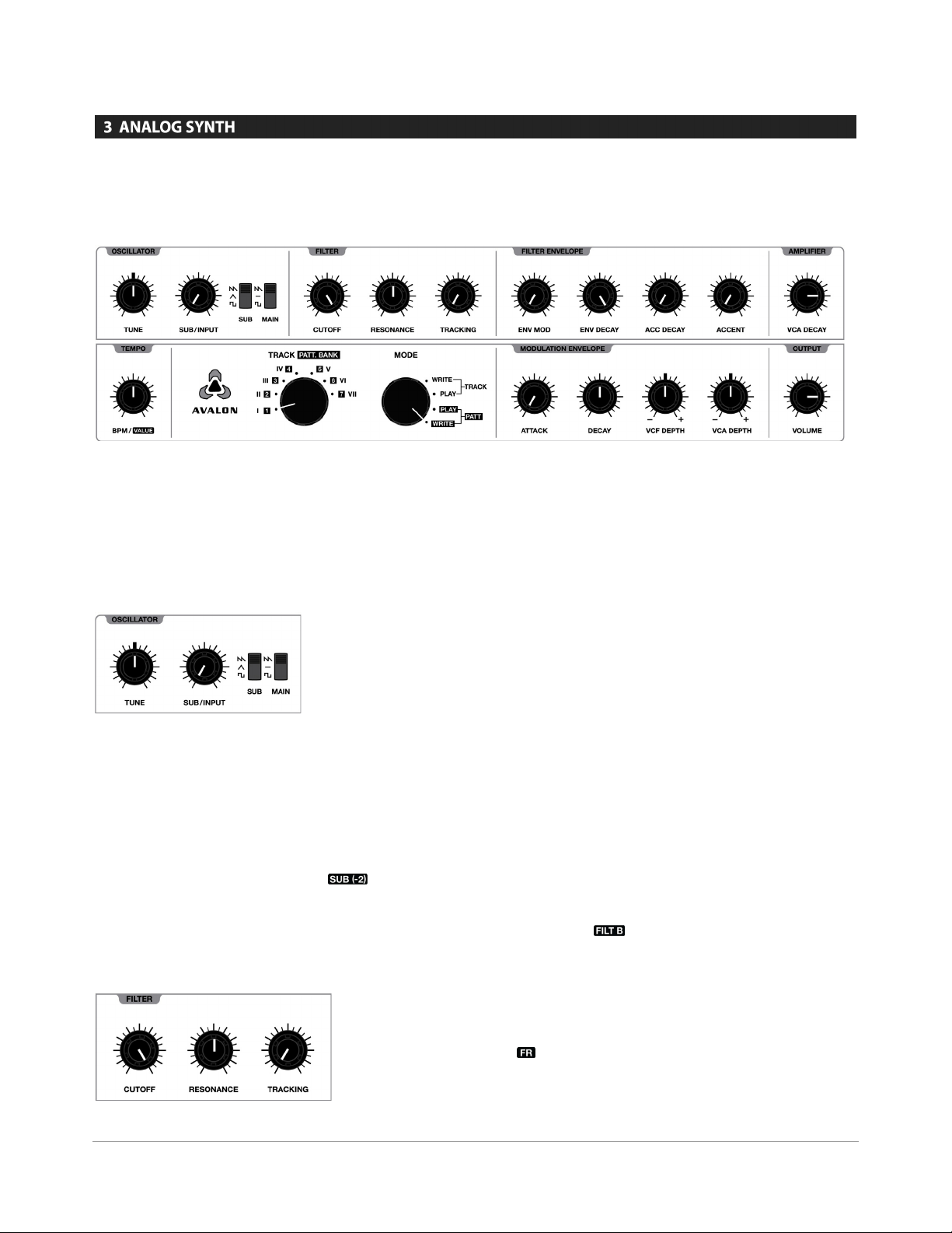
3 ANALOG SYNTH
3.1 ZERO THE SYNTHESIZER
Before starting to program a pattern it is a good idea to reset the analog synth voice to the default settings to ensure sound will be heard when a
pattern is played.
The analog voice of the Avalon is backwards compatible with the Roland® TB-303. The additional features can be viewed as a layer on top of the
original TB-303 which greatly expand the capabilities without being cumbersome or overwhelming. Together with the external filter cartridges
from the Synth Cartridge System™ the Avalon is an extremely flexible mono synth with capabilities far beyond the TB-303 subset of sound and
performance.
The analog controls are laid out in a straightforward manner.
3.2 OSCILLATOR
TUNE sets the master tune of the oscillators. The range of the control
is +/- 500 cents.
SUB/INPUT controls the level of the Sub Oscillator. When the external
input is used the Sub Oscillator is bypassed and it controls the
external input level.
The SUB and MAIN switches select the waveform for the main and
sub oscillators. When the main oscillator switch is set to the center
position the main oscillator is turned off. The switch selects
the sub oscillator between (-1) and (-2) octaves. When the switch is
pushed to the "in" position the sub oscillator is set to (-2) octaves and
the indicator lights up for visual confirmation.
3.3 FILTER
CUTOFF adjusts the cutoff frequency of the filter. The internal filter
is a low-pass diode ladder filter (TB-303), so in this case it controls the
low-pass cutoff frequency. External filter cartridges may have any
topology, so in these cases the CUTOFF control may relate to highpass, low-pass, band-pass, or notch frequency depending on the
topology and filter mode of the cartridge being used.
RESONANCE sets the emphasis amount at the cutoff frequency.
TRACKING sets the key tracking amount. This determines how
much the filter cutoff frequency tracks the keyboard. The tracking is
purposely non-linear with regards to keyboard scaling, so a one
octave increase in key pitch will never correspond to a one octave
increase in filter cutoff frequency for all notes. It is desirable to have a
greater response at lower octaves in a bassline synthesizer. In the
case of the Avalon the tracking is logarithmic, so tracking becomes
progressively greater at lower octaves and progressively gradual at
higher octaves. The changeover key for tracking is D#2 (77.78Hz), so
as tracking is increased notes below D#2 will decrease the filter cutoff
frequency and notes above it will increase the cutoff frequency.
The switch labeled is a hardware switch that selects between
the internal TB-303 filter and an external filter residing on an optional
filter cartridge. When the switch is in the 'out' position the internal
filter is selected. When the switch is pushed to the 'in' position the
filter plugin cartridge is selected and the LED indicator in the filter
section lights up for visual confirmation that the external cartridge
has been selected.
The switch stands for frequency response (or full range) and selects
the low frequency response of the audio signal to the VCA. When the
switch is in the 'out' position the frequency response rolls off at 70Hz.
11 AVALON - Reference Manual
When the switch is pushed to the 'in' position the frequency response
extends down below 30Hz.
The frequency response of the audio signal to the final amplifier in
the TB-303 (and hence the Avalon w/ default setting) is limited to ~70Hz.
This was done to maximize the signal-to-noise performance of the TB303 by removing the low frequency component of the signal that would
drive it into clipping faster. If exact TB-303 clone behavior is desired this
switch should be left in he 'out' position. However, for a full-range
response, especially when using the sub oscillator, you may want to
extend the frequency response.
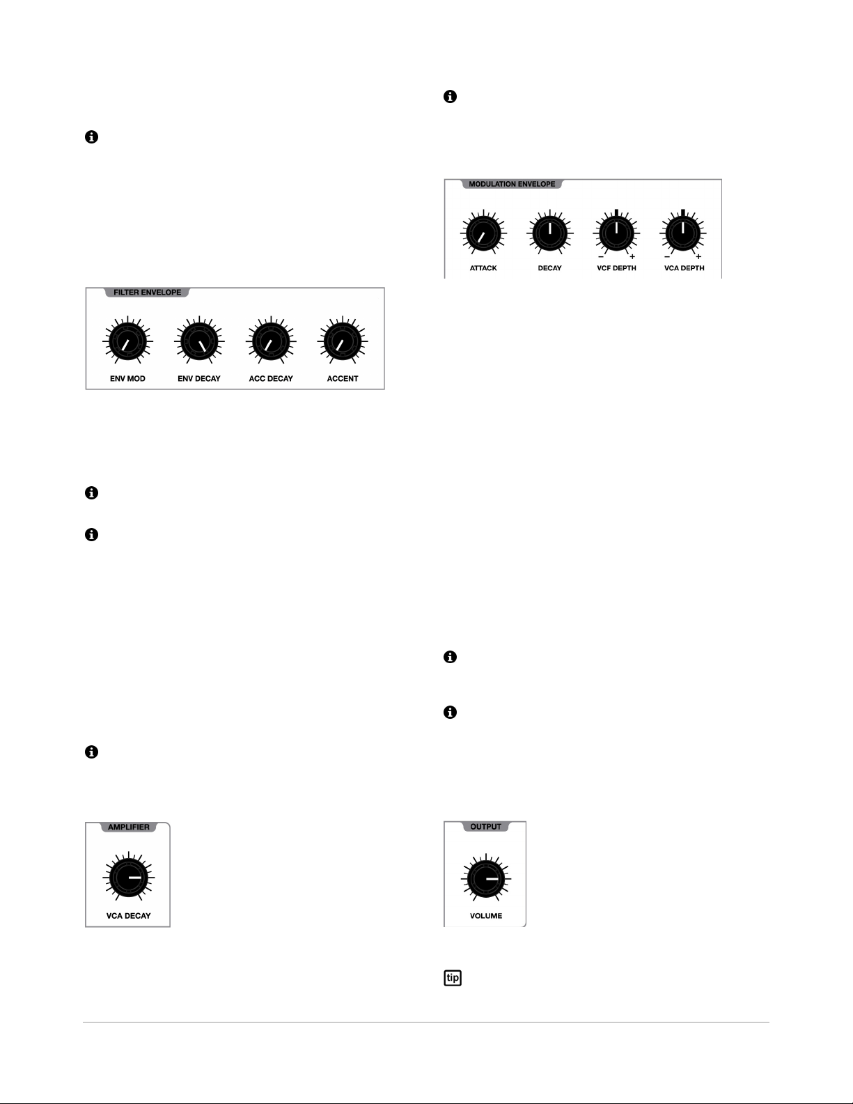
3.4 FILTER ENVELOPE
The filter envelope is a simple decay envelope. ENV MOD controls
the depth of the envelope modulation. ACC DECAY and ENV DECAY
set the decay time of the filter envelope for accented and unaccented
notes respectively. In both cases the decay time can be adjusted
between 200ms and 2s.
The implementation of the filter envelope and filter modulation in
general is non-standard. For specific details please see Appendix B.
The original TB-303 does not allow the filter envelope modulation to
be turned all the way off. The Avalon has an internal switch setting that
allows the filter envelope depth to maintain the TB-303 behavior. See
Appendix A for details.
When an accent has been programmed (or played) an additional
control voltage (envelope) is sent to the filter and final amplifier
(VCA). First, a copy of the filter envelope is sent to the VCA control
input to give a volume boost on accented notes. Second, a slewed
copy of the filter envelope is sent to the filter control input. This is
responsible for the characteristic wow sounds you can get with
accented notes. The character of this slewed version also varies with
the setting of the RESONANCE control, as increasing resonance also
increases the slew of this control voltage. The depth of this additional
accent modulation is determined by the ACCENT control.
For specific details on the behavior of accents on the filter and
amplifier see Appendix B.
3.5 AMPLIFIER
The VCA Envelope is identical to TB-303. While the decay time is
variable in the case of the Avalon, the attack is fixed to retain the
behavior of the TB-303. This envelope can be turned completely off by
setting VCA DECAY to the minimum setting.
3.6 MODULATION ENVELOPE
The modulation envelope is an additional attack-decay (AD) envelope
that can be used to modulate the filter and the final amplifier (VCA).
In addition to the dedicated filter and amp decay envelopes, this
modulation envelope allows for more complex modulation. The
modulation is bipolar and the envelope can be triggered on any step
of a sequence and manually in REALTIME modes.
ATTACK and DECAY set the attack and decay time of the envelope.
The attack time ranges from 0.9ms to 6s. The decay time ranges from
1.7ms to 10s.
VCF DEPTH and VCA DEPTH sets the amount of positive (+) or
negative (-) envelope modulation to the filter and VCA respectively.
VCF DEPTH has been designed with a progressive voltage offset for
increasing (+) or (-) modulations amounts. When the control is
rotated clockwise for (+) modulation a negative offset is applied to
the filter control input. Likewise, as an increasing (-) modulation
amount is set by rotating the control counter-clockwise a positive
offset is applied to the filter control input. See Appendix B for more
details.
VCA DEPTH has been designed with a progressive voltage offset for
negative (-) modulation amounts. When the control is rotated
counter-clockwise for (-) modulation a positive offset is applied to the
VCA control input. See Appendix B for more details.
The VCA Depth implementation as described above and in Appendix
B allows the VCA to be opened (drone mode) by setting the control for
maximum (-) modulation.
A key feature of the Avalon is the triggering of the modulation
envelope via the sequencer. The term "MOD ENV" as used in this manual
refers to programming or playing a modulation envelope trigger. This
should not be confused with "ENV MOD" , which is the name given to the
filter envelope depth control.
3.7 OUTPUT
VCA DECAY sets the decay time of the final amplifier (VCA) envelope.
The control ranges from off to 4s decay time.
12 AVALON - Reference Manual
VOLUME controls the output level.
There is a discrete "mixer" stage after the volume control. This is a
carryover from the TB-303 which has a Mix Input before the output jack.

In order to retain the same behavior the Avalon incorporates this same
circuit. This stage clips asymmetrically and can clip easily. If you hear
4 SEQUENCER OVERVIEW
4.1 PRIMARY MODES
The sequencer has (4) primary modes as indicated by the MODE
switch:
PATTERN WRITE
PATTERN PLAY
TRACK WRITE
TRACK PLAY
4.1.1 CHANGING PRIMARY MODES
The primary mode can be changed in realtime while the sequencer is
running.
4.1.1.1 BETWEEN PATTERN MODES
When changing the primary mode between pattern write and pattern
play modes the current pattern or pattern chain continues to play
uninterrupted.
4.1.1.2 BETWEEN TRACK MODES
When changing the primary mode between track write and track play
modes the current track continues to play uninterrupted.
4.1.1.3 BETWEEN PATTERN & TRACK MODES
When changing the primary mode from a track mode to a pattern
mode, the selected pattern will begin in sync at the end of the current
track step.
When changing the primary mode from a pattern mode to a track
mode, the selected track will start in sync after the current pattern or
pattern chain.
unwanted distortion in the main or phones outputs try turning down the
volume control.
4.2.2 PATTERN STEP ATTRIBUTES
Various pitch and time attributes can be entered for each step as
shown in the diagram below:
* attributes not found on the TB-303
4.2.3 PATTERN MODIFIERS
In addition to per STEP attributes there are top level pattern modifiers.
These are settings that are performed on the entire pattern as
opposed to the individual steps. These include parameters such as
the time signature and pattern length. These settings are saved with
each pattern.
4.2 WHAT IS A PATTERN?
Before continuing with details on pattern editing it is necessary to
understand the structure of a pattern. A pattern is a sequence of pitch
and time events, or steps.
4.2.1 THE PATTERN STEP
As is the case with traditional step sequencers, the PATTERN STEP is
the fundamental parameter of a pattern, representing a musical
event, such as a 1/16th note. Pattern steps relate directly to the (16)
lighted STEP BUTTONS on the control surface. These buttons are a
linear time representation of the pattern:
13 AVALON - Reference Manual
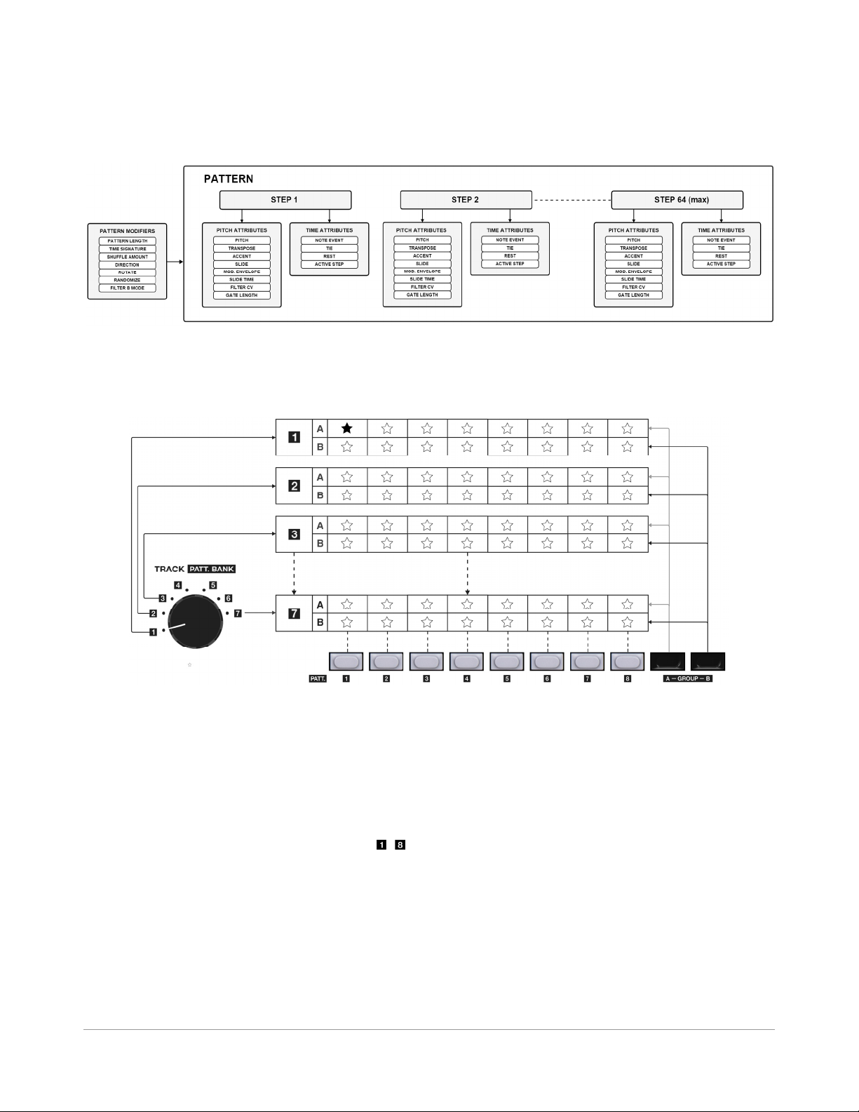
4.2.4 PATTERN OVERALL STRUCTURE
Below is a diagram of the overall pattern structure:
4.3 PATTERN SELECTION
The Avalon has (112) internal patterns. Patterns are organized into (7) banks with (16) patterns within each bank. The (16) patterns of each bank are
further organized into two groups of eight.
4.3.1 PATTERN BANK
First, select one of seven pattern banks with the PATT. BANK selector.
4.3.2 PATTERN GROUP
Second, select Group A or Group B with the GROUP A-B buttons.
4.3.3 PATTERN NUMBER
Lastly, select a pattern number using the PATTERN BUTTONS - .
4.4 PATTERN PLAYBACK
To play back a pattern using internal sync Press RUN while in
PATTERN PLAY or PATTERN WRITE MODE. Set the TEMPO control so
that you can see the step indicators running across the sixteen steps.
The RUN indicator is lit when the sequencer is running.
For information on sequencer sync options, including how to slave
the Avalon to DINSync or MIDI please see section 10.1.
4.4.1 TEMPO
Set the tempo using the TEMPO control. The tempo ranges from 40 300BPM.
14 AVALON - Reference Manual
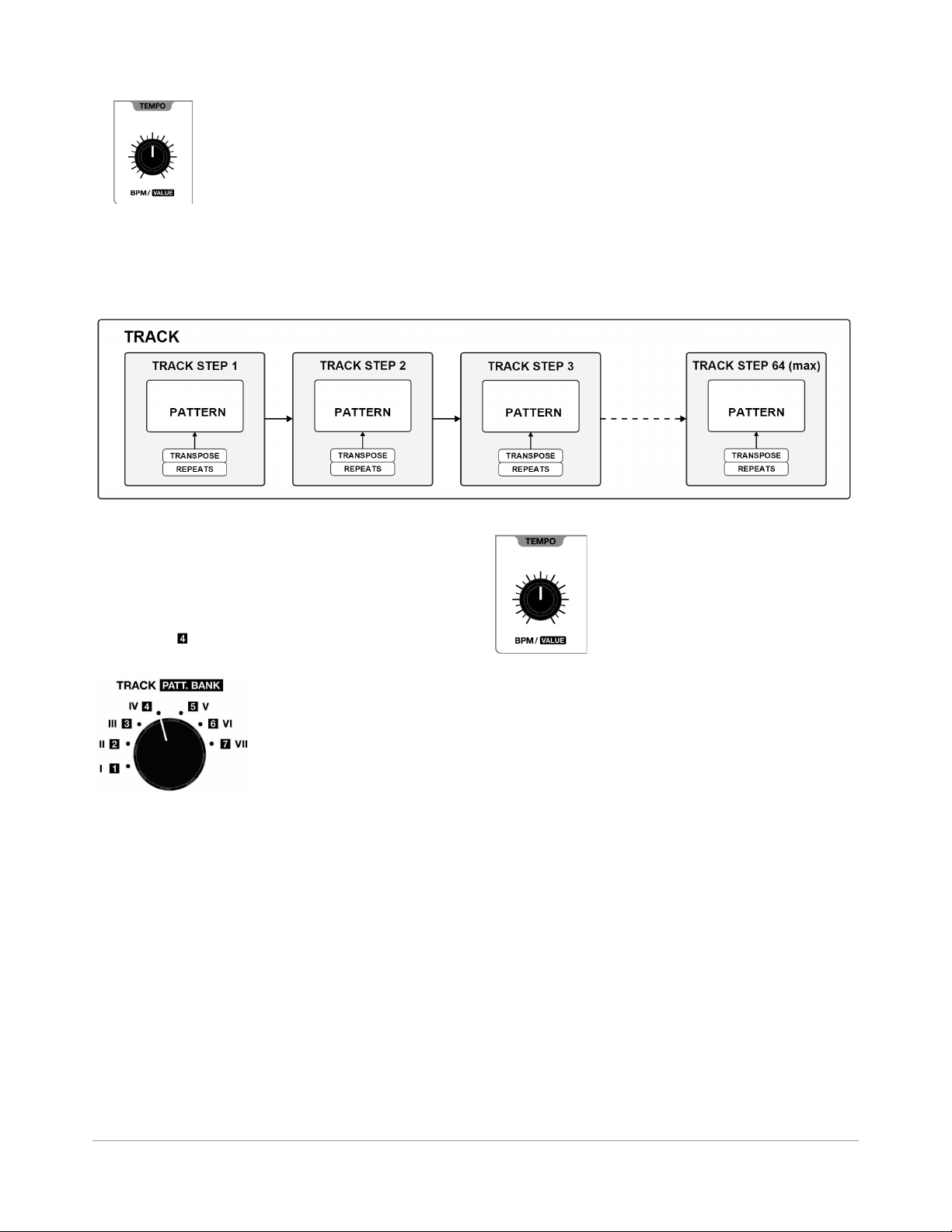
4.5 WHAT IS A TRACK?
A TRACK is a sequence of PATTERNS. TRACKS are used to compose entire songs from one or more patterns.
Each TRACK is made up of a series of TRACK STEPS. A TRACK can contain up to (64) individual TRACK STEPS. Each TRACK STEP can have it's own
transpose value and number of repeats.
4.6 TRACK SELECTION
The Avalon has (7) internal tracks. Tracks are selected using the rotary
switch and are denoted by the roman numerals I through VII. Tracks
are made up of patterns within the pattern bank that corresponds to
the track number. For example, TRACK IV uses patterns that reside in
PATTERN BANK .
4.7 TRACK PLAYBACK
To play back a track using internal sync Press RUN while in TRACK
PLAY MODE. Set the TEMPO control so that you can see the step
indicators running across the sixteen steps. The RUN indicator is lit
when the sequencer is running.
For information on sequencer sync options, including how to slave
the Avalon to DINSync or MIDI please see section 10.1.
TEMPO
Set the tempo using the TEMPO control. The tempo ranges from 40 300BPM.
15 AVALON - Reference Manual
 Loading...