

ABSOLARE Push-Pull Amplifier
User Manual

2
ABSOLARE Push-Pull Amplifier User Manual 0.9

3
ABSOLARE Push-Pull Amplifier User Manual 0.9
Contents'
1.#General#Description#..............................................................................................................#4#
2.#Safety#Issues#and#Warnings#..................................................................................................#4#
3.#Unpacking#and#Placement#....................................................................................................#5#
4.#Installing#the#Tubes#..............................................................................................................#6#
5.#Connecting#the#Cables#..........................................................................................................#9#
5.1.#Power#cables#..................................................................................................................#9#
5.2.#Signal#Cables#..................................................................................................................#9#
5.3.#Speaker#Cables#...............................................................................................................#9#
6.#Operating#the#Unit#..............................................................................................................#10#
6.1.#General#Operation#.......................................................................................................#10#
6.2.#Setting#the#Bias#Levels#.................................................................................................#10#
6.2.1.#845#Bias#Levels#......................................................................................................#11#
6.2.2.#EL34#Bias#Levels#.....................................................................................................#12#
7.#Troubleshooting#and#Maintenance#....................................................................................#13#
8.#Technical#Specifications#......................................................................................................#13#

4
ABSOLARE Push-Pull Amplifier User Manual 0.9
1.#General#Description#
The Absolare Push-Pull Amplifier is a transformer coupled, zero feedback, two
chassis monoblock stereo amplifier with an all tube signal path and point-to-point
construction. Transformer Balanced (XLR) and Single-ended (RCA) input versions
are available.
2.#Safety#Issues#and#Warnings#
- - Ensure the voltage setting of the unit matches the voltage of the available AC
power. Operating voltage is fixed and must only be changed by an authorized
service agent.
- Do not touch tubes while operating. Tubes are extremely hot devices and also
contain very high voltages.
- There are no user serviceable parts inside the units. Do not open bottom covers.
- Do not operate the amplifier without an output load. 4 – 8 ohm speakers or
equivalent load should be connected to speaker terminals when the amplifier is
operating.
5
ABSOLARE Push-Pull Amplifier User Manual 0.9
3.#Unpacking#and#Placement#
The monoblock amplifiers are supplied in separate boxes. After opening the top
cover of the box, remove the upper layer of hard foam material. You can then lift the
units from the box using the cloth underneath each chassis.
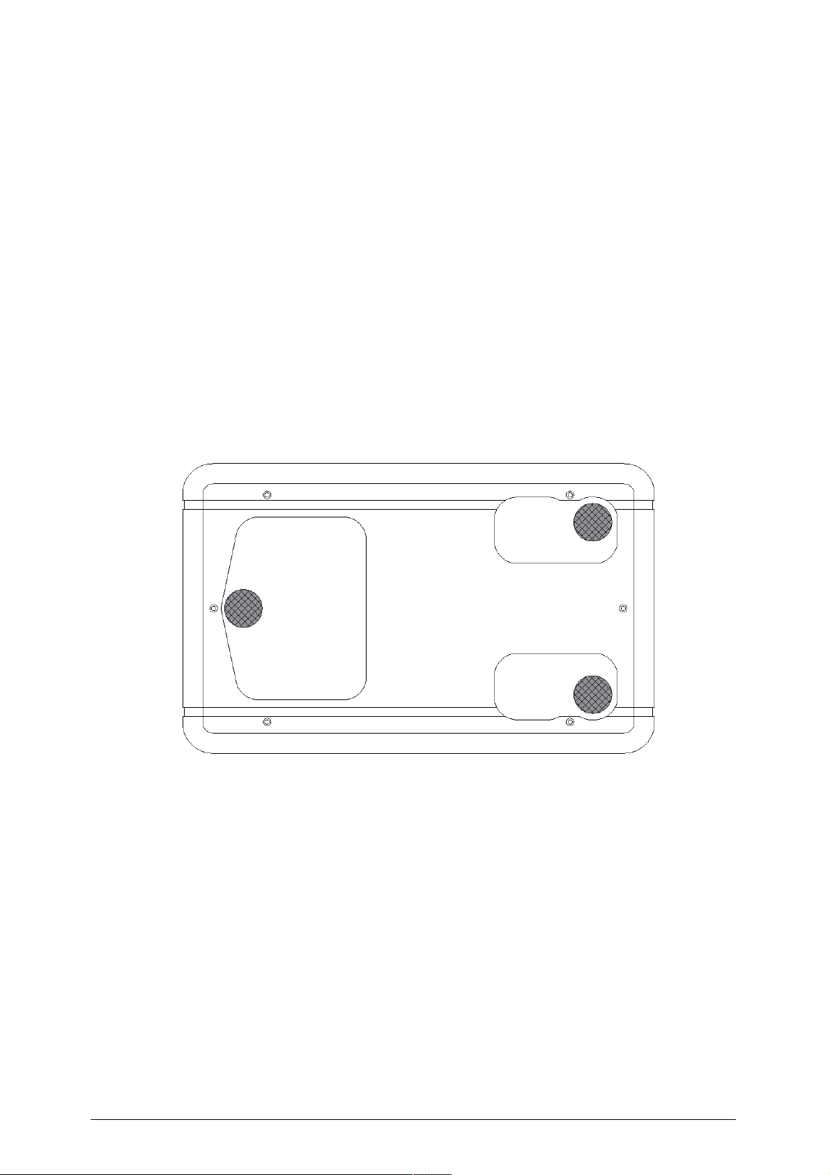
Feet can affect the sound quality significantly. Feet should be placed directly under
the aluminum base plate, not the MDF/leather plate. There are three areas where
the aluminum base plate is exposed through openings in the bottom MDF/leather
plate. These areas are where feet should be placed. You can use either three or four
feet. Adjusting their position will also affect the sound to varying degrees, depending
on the type of rack, location or interaction with other equipment. For most situations
the arrangement as shown in the diagram below is a good starting point.

6
ABSOLARE Push-Pull Amplifier User Manual 0.9
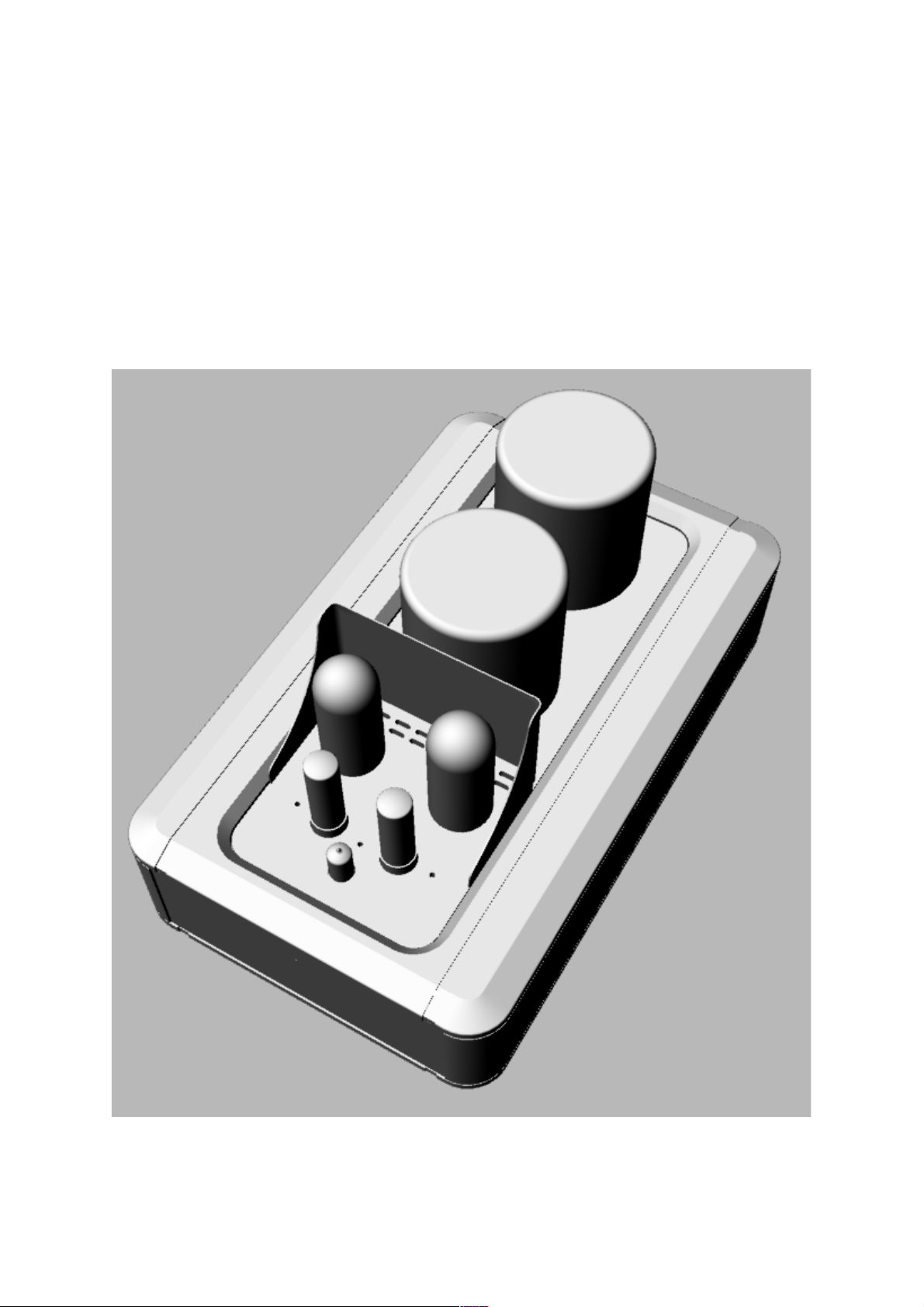
4.#Installing#the#Tubes#
There are total of 5 tubes in each monoblock. Placement of tubes is shown below:
7
ABSOLARE Push-Pull Amplifier User Manual 0.9
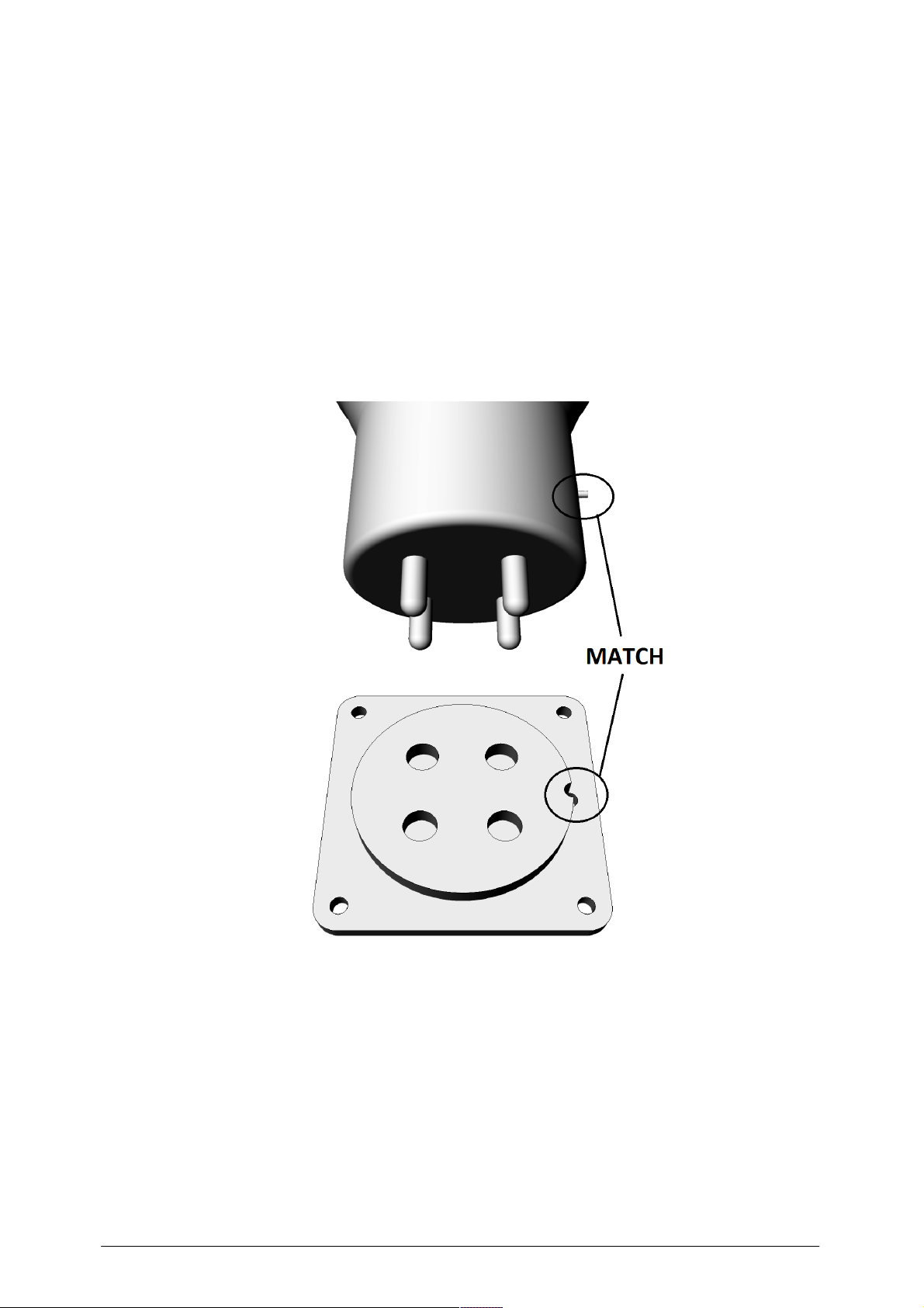
845 tubes must be installed in the correct orientation. The small indicator pin on the
lower side of the tube base should match the small hole on the right-side of the tube
socket, as illustrated in the figure below.
CAUTION: Incorrect positioning of 845 may seriously damage the amplifier!

8
ABSOLARE Push-Pull Amplifier User Manual 0.9
EL34 tubes have a small bump in the center as a key for correct positioning. Align it
with the corresponding notch in the tube socket while inserting.
12AT7 / ECC81 tube has one missing pin acting as a correct positioning key. Align
missing pin with the missing hole in the tube socket while inserting.

9
ABSOLARE Push-Pull Amplifier User Manual 0.9
5.#Connecting#the#Cables#
5.1.$Power$cables$
AC power input is via a standard IEC socket. Operating voltage must only be
changed by an authorized service agent.
The quality of the power cable used will affect the sound quality.
5.2.$Signal$Cables$
Single-ended version has only one RCA input connector. Balanced version has both
RCA and XLR input connectors. The RCA and XLR inputs are connected in parallel
inside the unit. Do not connect two source devices at the same time. A selector
switch (marked as SEL) allows you to bypass the input transformer. When the input
transformer is bypassed, the sound level will increase due to level differences of
balanced and unbalanced connection standards, but you lose true balanced input
features and the system may become more susceptible to noise.
5.3.$Speaker$Cables$
Speaker binding posts can handle spade lugs, banana plugs or bare wire.
Polyethylene knobs are chosen instead of metal ones to reduce extra conductor
mass and eddy currents. Do not overtighten the binding posts. The higher friction of
polyethylene will secure the speaker cables.
There are two impedance options for speaker connection. You should use the
closest matching output with your speaker manufacturer’s recommended value.
Since the output is transformer coupled, there is no output power difference when
using 4 or 8 ohm speakers.
Always use a combination of 0+4 ohm or 0+8 ohm terminals. Never combine 4 ohm
and 8 ohm terminals as a 4 ohm output.
10
ABSOLARE Push-Pull Amplifier User Manual 0.9
6.#Operating#the#Unit#
6.1.$General$Operation$
Before turning on the unit be sure that all tubes are installed and all cables
connected correctly.
If you have changed 845 tubes you should first minimize the bias settings (by
rotating to counter-clockwise) before turning-on the amplifiers and re-adjust the bias
settings. Please refer the bias settings section (6.2.1).
After turning on, the power indicator LED on the front plate will start to blink. Sound
will only be audible after all capacitors inside are charged and internal voltages are
stabilized (after that the indicator LED starts to illuminate continuously).
Absolare Push-Pull Amplifier will be ready to operate approx. 40 seconds after
turning on the power, but attaining full performance may take 15 to 30 minutes.
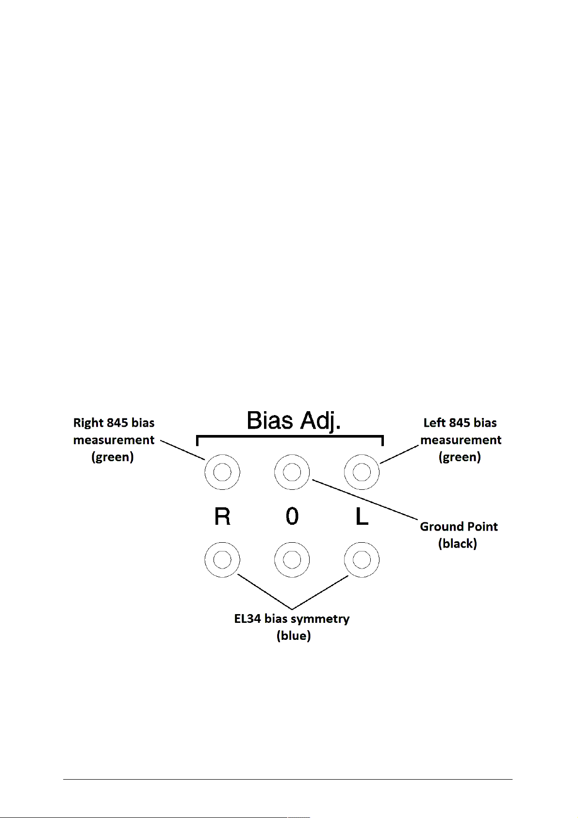
6.2.$Setting$the$Bias$Levels$
Measurement points for the bias levels are at the back cover:

11
ABSOLARE Push-Pull Amplifier User Manual 0.9
6.2.1.$845$Bias$Levels$
You have to adjust left and right 845 tube bias levels separately. Measurement is
done via a multimeter at 2V DC (or 2000mV DC) setting. Insert black (-) probe into
black socket and red (+) probe into one of the green sockets. You should read a
value about 0.45V (450mV) for each tube. If the readings are different, then adjust
the bias level via potentiometers near the EL34 tubes. A small flat screwdriver will be
necessary to access internal bias pots.

12
ABSOLARE Push-Pull Amplifier User Manual 0.9
6.2.2.$EL34$Bias$Levels$
There is no separate bias adjustments for EL34 tubes, but the push-pull symmetry is
important. With a multimeter at lowest DC volt measurement setting, insert black and
red probes into blue sockets. The adjustment point is in between the EL34 sockets.
You should try to get 0.0V or near by turning the adjustment pot with a small flat
screwdriver. If you cannot cross the zero value (i.e. you only get positive or negative
values in entire adjustment range) you should turn off the unit, wait until tubes are
cooled down, swap EL34’s and repeat the adjustment procedure above. This
happens when one of the EL34 tube gain is very different than the other one. If
swapping the tubes does not solve the issue then you should replace at least one of
the tubes or install a gain matched pair.

13
ABSOLARE Push-Pull Amplifier User Manual 0.9
7.#Troubleshooting#and#Maintenance#
Surface of the unit is dirty.
Clean with a slightly damp cloth.
No power light.
- Check AC line voltage.
- Check the main fuse.
Power light is on but 845 tube heaters
are not glowing.
- Tube orientation is wrong, turn-off the
immediately and correct the installation.
- Tube(s) are defective.
Power light is on, tube heaters are
glowing, but no sound.
- Check the input cables , speaker cables
and source.
- Internal fuse for 845 tubes may be
blown out. Call your dealer.
Noise / hum in the sound.
- Check grounding of power, input cables
and source.
If the problem is persistent, contact your nearest ABSOLARE dealer.
8.#Technical#Specifications#
- Substantially operating in Class A, Zero Feedback, Push-Pull architecture.
- Point-to-point construction.
- Tubes: 2 x 845, 2 x EL34, 1 x 12AT7 / ECC81 (for each monoblock).
- Output power: 85 Watts
- Input: 1 x RCA (transformer balanced XLR optional)
- Input Sensitivity: 1.5 Volts (balanved version 6 Volts)
- Input impedance: 100 kOhm
- Speaker impedance: 4 – 8 Ohms
- Bandwidth: 15 Hz – 35 KHz +/- 1.0 dB
- Dimensions: 38.2 x 62.2 x 29.5 cm (W x D x H),excluding feet.
- Weight: 42.0 Kg (each monoblock)

ABSOLARE USA LLC
40 Pemberton Road, Nashua New Hampshire, 03063
Phone: +212-229-1842
E-mail: info@absolare.com
ABSOLARE SERVICE EUROPE
Mozartstraat 157, 1962AL Heemskerk, Netherlands
Phone: +31 61 399 3049
E-mail: info@absolare.nl
© 2015 ABSOLARE
 Loading...