

Page 1
ABSCO PREMIER SHED
MANU FACT URED
IN A US TR ALIA
SNAPTiTE
Assemb ly
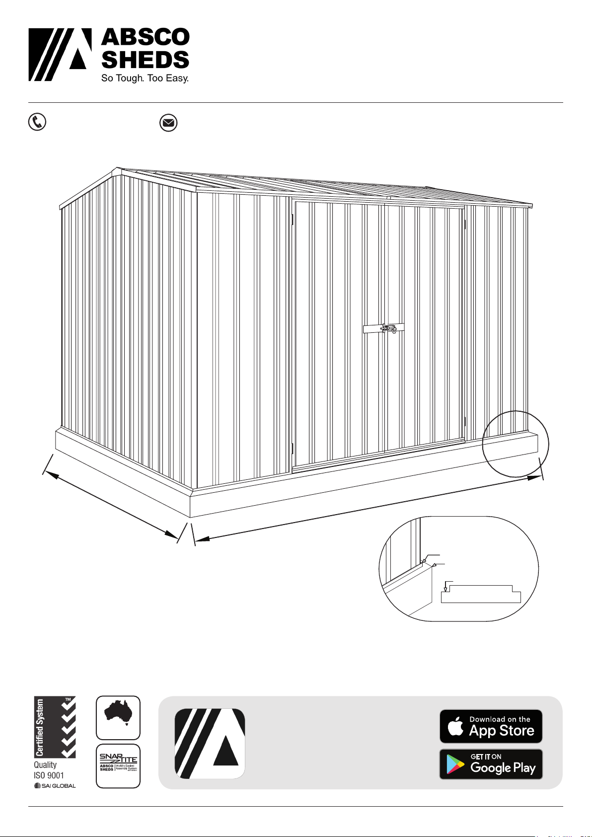
2360mm
FRONT: 2.26m
SIDE: 1.52m
HEIGHT: 1.95m
MODEL: 30302GK
3.00mW x 3.00mD x 2.10mH
AU: 1800 029 701
N Z: 0800 466 444
[email protected]
www.abscosheds.com.au
3100mm
For construction in non-cyclonic areas
Wind rating: N2 as per AS4055-2012.
If you require a higher wind rating please contact
us: [email protected] or 1800 029 701
NOTE: This shed can be upgraded to wind
rating: C1 as per AS4055-2012 with the additional
purchase of a Cyclone Kit.
CONCRETE SLAB
3100mm
BOTTOM CHANNEL
REBATED EDGE
100mm
75mm WIDE REBATE
CONCRETE
CONCRETE SLAB
When laying concrete slab, ensure there
is a rebated edge 25mm deep around
the perimeter. This will help water egress
from the base of the shed.
Absco Industries Assembly Instruction Manual
Download the Absco
Sheds Assembly App
for instructional videos
Model: 30302GK 1.20
10/05/19
1
Page 2

ABSCO PREMIER SHED
MODEL: 30302GK
3.00mW x 3.00mD x 2.10mH
GENERAL INSTRUCTIONS
• Before commencing any assembly, read through these instructions in detail to gain a thorough
understanding of assembly methods and associated details.
• Unpack the carton and carefully identify and check off all the parts against the parts described
and illustrated on "COMPONENTS PACKING LIST" pages.
SITE PREPARATION
• The site for the shed must be level. An uneven surface may result in misalignment of parts.
• The shed shall be erected on top of a reinforced concrete slab and anchored down appropriately
illustrated on “FINAL CONSTRUCTION” page.
TOOLS REQUIRED
3mm drill bit
SAFETY NOTES
• Some parts may have sharp edges. It is advisable to wear gloves when handling these items and
safety glasses if drilling holes. Sensible shoes are highly recommended.
• Do not erect your shed in windy conditions.
• Ensure that the shed is securely anchored to a solid foundation immediately after construction is
completed.
• It is highly recommended to erect the shed with two or more people.
RECOMMENDED
10mm drill bits
metal & masonry
Absco Industries Assembly Instruction Manual
Model: 30302GK 1.20
10/05/19
2
Page 3
ABSCO PREMIER SHED
MODEL: 30302GK
3.00mW x 3.00mD x 2.10mH
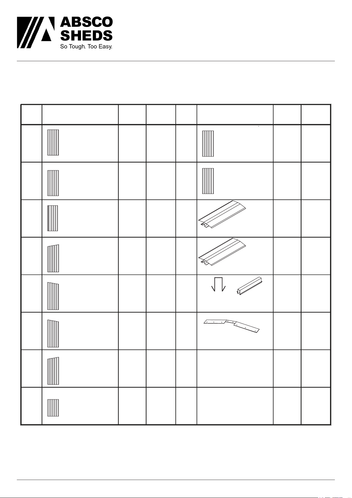
COMPONENT PACKING LIST
Check off all components.
QTY QTY
2
2
2
2
COMPONENT
DESCRIPTION
STEEL SHEET
1785mm X 773mm
STEEL SHEET
1785mm X 773mm
STEEL SHEET
1785mm X 711mm
STEEL SHEET
1915mm X 773mm
PART
No.
30A
31A
34A
36L
CHECK
1
1
1
1
COMPONENT
DESCRIPTION
STEEL SHEET
1725mm X 773mm
STEEL SHEET
1725mm X 773mm
RIDGE
BEAM
L = 1521mm (59.9")
RIDGE
BEAM
L = 1521mm (59.9")
PART
No.
A
B
97AL
97AR
CHECK
2
2
2
8
STEEL SHEET
1915mm X 773mm
STEEL SHEET
2045mm X 773mm
STEEL SHEET
2045mm X 773mm
STEEL SHEET
1546mm X 773mm
36R
38R
38L
45A
1
2
RIDGE BEAM JOINER
ZARSP
L: 450mm (17.7")
15A
PEAK BRACE
Absco Industries Assembly Instruction Manual
Model: 30302GK 1.20
10/05/19
3
Page 4
ABSCO PREMIER SHED
MODEL: 30302GK
3.00mW x 3.00mD x 2.10mH
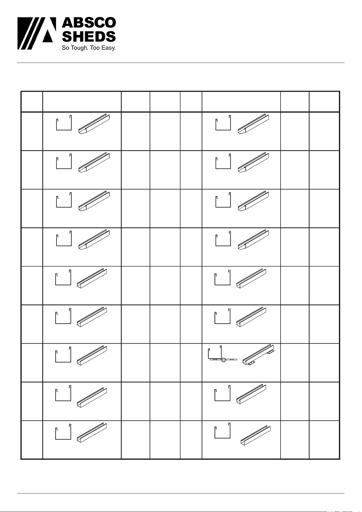
COMPONENT PACKING LIST
QTY
1
1
1
1
COMPONENT
DESCRIPTION
CHANNEL
L = 1496.5mm (58.9")
CHANNEL
L = 1496.5mm (58.9")
CHANNEL
L = 1496.5mm (58.9")
CHANNEL
L = 1496.5mm (58.9")
PART
No.
55AL
55CL
55BL
81BL
CHECK
QTY
1
1
1
1
COMPONENT
DESCRIPTION
CHANNEL
L = 1496.5mm (58.9")
CHANNEL
L = 1496.5mm (58.9")
CHANNEL
L = 1496.5mm (58.9")
CHANNEL
L = 1496.5mm (58.9")
PART
No.
55AR
55CR
55BR
81BR
CHECK
4
CHANNEL
L = 1496.5mm (58.9")
2
CHANNEL
L = 1496.5mm (58.9")
4
CHANNEL
L = 773mm
1
CHANNEL
L = 1568mm
2
CHANNEL
L = 1518mm
81AL
60AL
58C
79A
84R
4
CHANNEL
L = 1496.5mm (58.9")
2
CHANNEL
L = 1496.5mm (58.9")
2
CHANNEL WITH HINGES
L = 1725mm
1
CHANNEL
L = 1725mm
2
CHANNEL
L = 1518mm
81AR
60AR
58A
58B
84L
Absco Industries Assembly Instruction Manual
Model: 30302GK 1.20
10/05/19
4
Page 5
ABSCO PREMIER SHED
MODEL: 30302GK
3.00mW x 3.00mD x 2.10mH
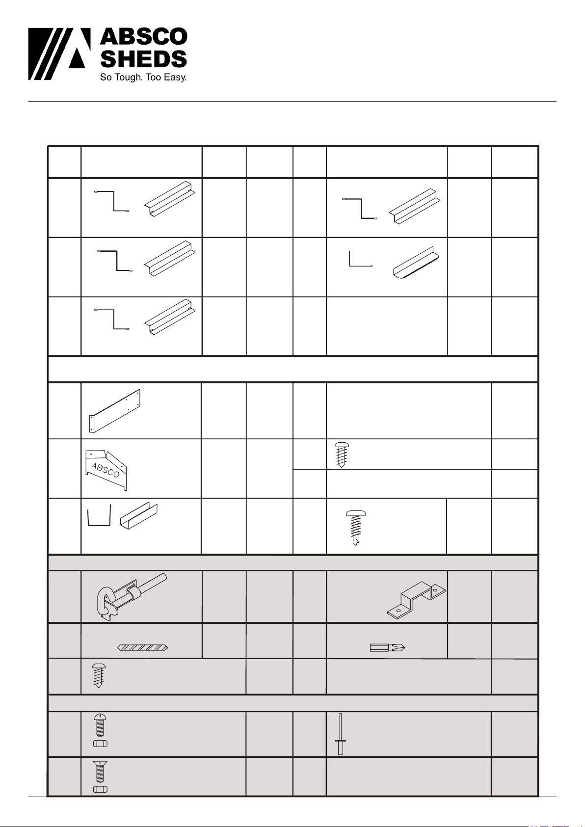
COMPONENT PACKING LIST
QTY QTY
COMPONENT
DESCRIPTION
1
JAMB L= 1568mm
2
JAMB L= 1785mm
1
JAMB L= 1725mm
PART
No.
90A
89A
89C
CHECK
4
4
INSTRUCTIONS & FITTINGS PACKET
DOOR
2
STRAP
L: 165mm
12A
1
COMPONENT
DESCRIPTION
JAMB L= 1120mm
LIP TRIM L= 1546mm
ASSEMBLY
INSTRUCTIONS
PART
No.
91A
87A
CHECK
2
10
3
CHANNEL JOINER
L= 200mm (7.9")
3mm DRILL BIT
CAP GABLE
L: 170mm
PSTKDBL - DOUBLE DOOR FITTINGS PACK
DOOR
PADBOLT
1 1
1
8
SELF TAPPING SCREWS
PACKET CONTAINING 220
3/16 ROUND HEAD
BOLTS & NYLOCK NUTS
14A
CSJ
DRILL
PACK12P - SCREW PACK 12
1
1
10
2
1
12
SELF TAPPING SCREWS
PACKET CONTAINING 100
PSTKDBL
DOUBLE DOOR FITTINGS PACK
16mm TEK
SCREWS
DOOR
PADBOLT
HASP
PHILLIPS DRIVER BIT
PACK12P
SCREW PACK 12
3.2 x 8mm
BLIND POP RIVETS
FAST014
FAST007FAST006
FAST038
3/16 COUNTERSUNK
12
Absco Industries Assembly Instruction Manual
SCREWS & NUTS
Model: 30302GK 1.20
10/05/19
5
Page 6

ABSCO PREMIER SHED
MODEL: 30302GK
3.00mW x 3.00mD x 2.10mH
SNAPTiTE ASSEMBLY GUIDE
The Snaptite Assembly System locks end channels to all roof and wall sheets without the need for
tools and fasteners.
To assemble each panel, the perimeter channels are secured to the top and bottom of each panel.
Gently tap the channel over the SNAPTiTE lugs on the sheet, working along the sheet.
Each perimeter channel must fi nish fl ush with the edges of the sheets. Simply tap the channel along
the sheets until each end is neatly fl ush. If you need to remove channels from the panels, slide it off
from the side.
FASTENING SYMBOLS
SNAP
Secure channel to sheeting by SNAPTiTE
T TE
i
fastening method.
Join components together with one
screw at this location only, as some
channels have extra holes that are not
required for this model of shed.
Do not join components together at
this location yet, as the screws may
obstruct further assembly of the other
components.
Channel locks the shed panel into
position without the need for screws!
D
Join components together by pre-drilling the holes fi rst. Use one component as
template to mark where the holes are and
drill with a 3mm drill bit.
3mm pop rivet
4mm nut and bolt set.
Absco Industries Assembly Instruction Manual
Model: 30302GK 1.20
10/05/19
6
Page 7

ABSCO PREMIER SHED
MODEL: 30302GK
3.00mW x 3.00mD x 2.10mH
Guide on Joining Spliced Channels
The text marked on all parts must be shown on the same side as each other
= =
CSJ
JOIN>> <<JOIN
Step 1.
Position the channels and the
CSJ joiner so the centre of
the CSJ is in line with the end
of each channel to be joiner
together.
= =
JOIN>>
<<JOIN
=
=
JOIN>>
J
Step 2.
Join the fi rst channel to the CSJ
by inserting the centre of the
CSJ, on an angle, to the end of
the channel where the JOIN>>
text is marked.
JOIN>> <<JOIN
= =
==
JOIN>>
SJ
Push down one side of the CSJ
until you hear a ‘click’.
Drill out holes with 3mm drill
bit in CSJ to match the holes
in channel and secure with the
screws supplied.
These may have to be
temporarily removed during
assembly.
Step 3.
Join the second channel to the
CSJ by positioning the <<JOIN
of the channel at the centre of
the CSJ, on an angle. Push the
Finished Channel.
The joined channels should
now look like the picture with
the CSJ positioned equally
inside of the joined channels.
CSJ into the channel until you
hear a ‘click’.
Absco Industries Assembly Instruction Manual
Push
...
20mm 15mm
Finished Spliced
Channel
Model: 30302GK 1.20
10/05/19
CSJ
.
Channel
7
Page 8

ABSCO PREMIER SHED
MODEL: 30302GK
3.00mW x 3.00mD x 2.10mH
PRE-ASSEMBLY OF SPLICED CHANNELS
Join together 16 x channel sections using 8 x channel joiners (Part CSJ)
NOTE: Some channels may have holes in them - You will
need to redrill holes where CSJ joining channel covers
them.
81AR
2993mm
= 4x 81A
= 2x 60A
4x 81AR
4x 81AL
2x 60AR
2x 60AL
1x 55AR
1x 55AL
1x 55CR
1x 55CL
81AL
60AL
55AL
55CL
55BL
60AR
= 1x 55A
55AR
= 1x 55C
55CR
= 1x 55B
55BR
= 1x 81B
81BR
1x 55BR
1x 55BL
81BL
1x 81BR
1x 81BL
Absco Industries Assembly Instruction Manual
Model: 30302GK 1.20
10/05/19
8
Page 9
ABSCO PREMIER SHED
MODEL: 30302GK
3.00mW x 3.00mD x 2.10mH
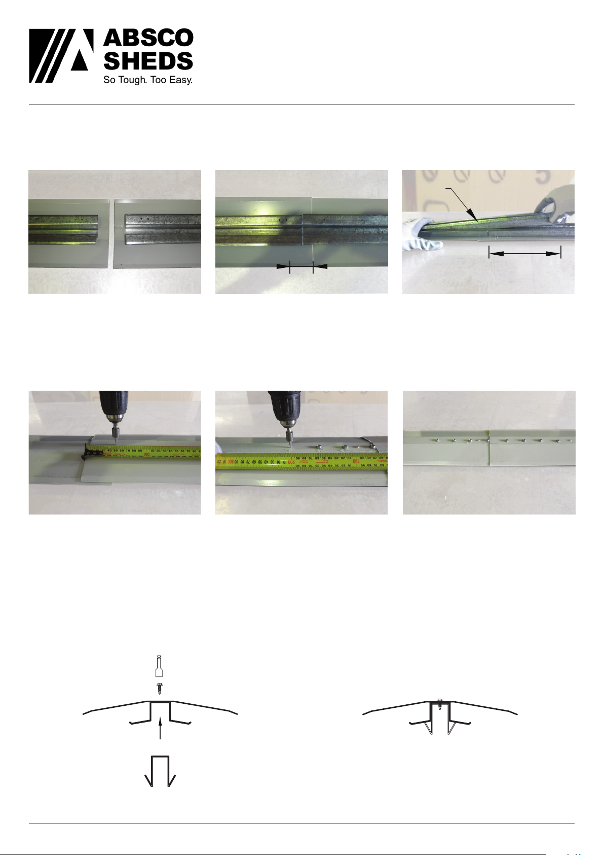
Guide on Joining a Spliced Ridge Beam
Follow these three steps to assemble a ridge beam.
50mm
ZARSP
225mm
Step 1.
Place two ridge beams as
shown and push them together.
Slide the cap of one under the
other.
Step 3.
Turn over the ridge beam.
Measure 250mm from the
middle along the centre of one
ridge beam, mark spacings of
50mm. Fasten with a Tek screw
at each marking.
NOTE.
There is a 50mm overlap of the
ridge caps when the beams are
in position.
Repeat to the other side of the
ridge beam assembly.
TIP: Predrilling each hole with
the 3mm drill bit makes it easier
to fasten.
Step 2.
Use the ZARSP to connect at
the centre of the two ridge
beams. Be sure it is pushed in
fully.
Finished Spliced Ridge Beam
Tek screw driver bit
Self drilling Tek screw
Ridge Beam
Push
ZARSP
Absco Industries Assembly Instruction Manual
Finished
Spliced Ridge Beam
Model: 30302GK 1.20
10/05/19
9
Page 10
ABSCO PREMIER SHED
MODEL: 30302GK
3.00mW x 3.00mD x 2.10mH
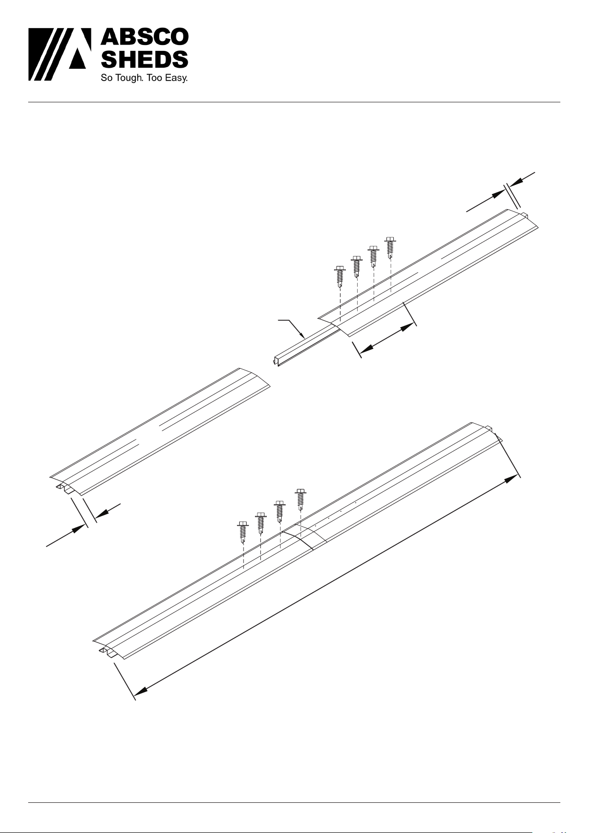
PRE-ASSEMBLY OF SPLICED RIDGE BEAM
ZARSP
16mm
97AR
16mm
97AL
225mm
2993mm Overall length
= 1x 97A
.
.
1x 97AL
1x 97AR
Absco Industries Assembly Instruction Manual
Model: 30302GK 1.20
10/05/19
10
Page 11
ABSCO PREMIER SHED
MODEL: 30302GK
3.00mW x 3.00mD x 2.10mH
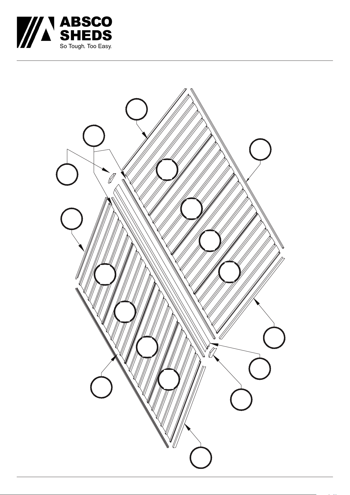
OVERVIEW OF ROOF COMPONENTS
87A
60A
81A
14A
87A
45A
45A
45A
45A
45A
45A
87A
45A
81A
OVERVIEW OF ROOF COMPONENTS
Absco Industries Assembly Instruction Manual
97A
45A
14A
87A
Model: 30302GK 1.20
10/05/19
11
Page 12
ABSCO PREMIER SHED
MODEL: 30302GK
3.00mW x 3.00mD x 2.10mH
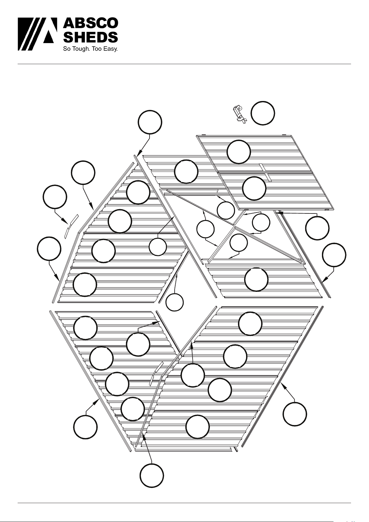
OVERVIEW OF WALL COMPONENTS
55A
22A
B
15A
84R
84L
36R
30A
38R
38L
36L
81B
90A
81A
34A
91A
A
89A
91A
79A
89A
55C
34A
36R
31A
31A
30A
55B
OVERVIEW OF WALL COMPONENTS
Absco Industries Assembly Instruction Manual
84L
38R
84R
38L
81A
36L
Model: 30302GK 1.20
10/05/19
12
Page 13

REAR PANEL ASSEMBLY
1x required.
ABSCO PREMIER SHED
MODEL: 30302GK
3.00mW x 3.00mD x 2.10mH
30A
31A
31A
30A
SNAP
55B
TE
i
T
81B
TE
i
T
SNAP
Absco Industries Assembly Instruction Manual
Model: 30302GK 1.20
10/05/19
13
Page 14
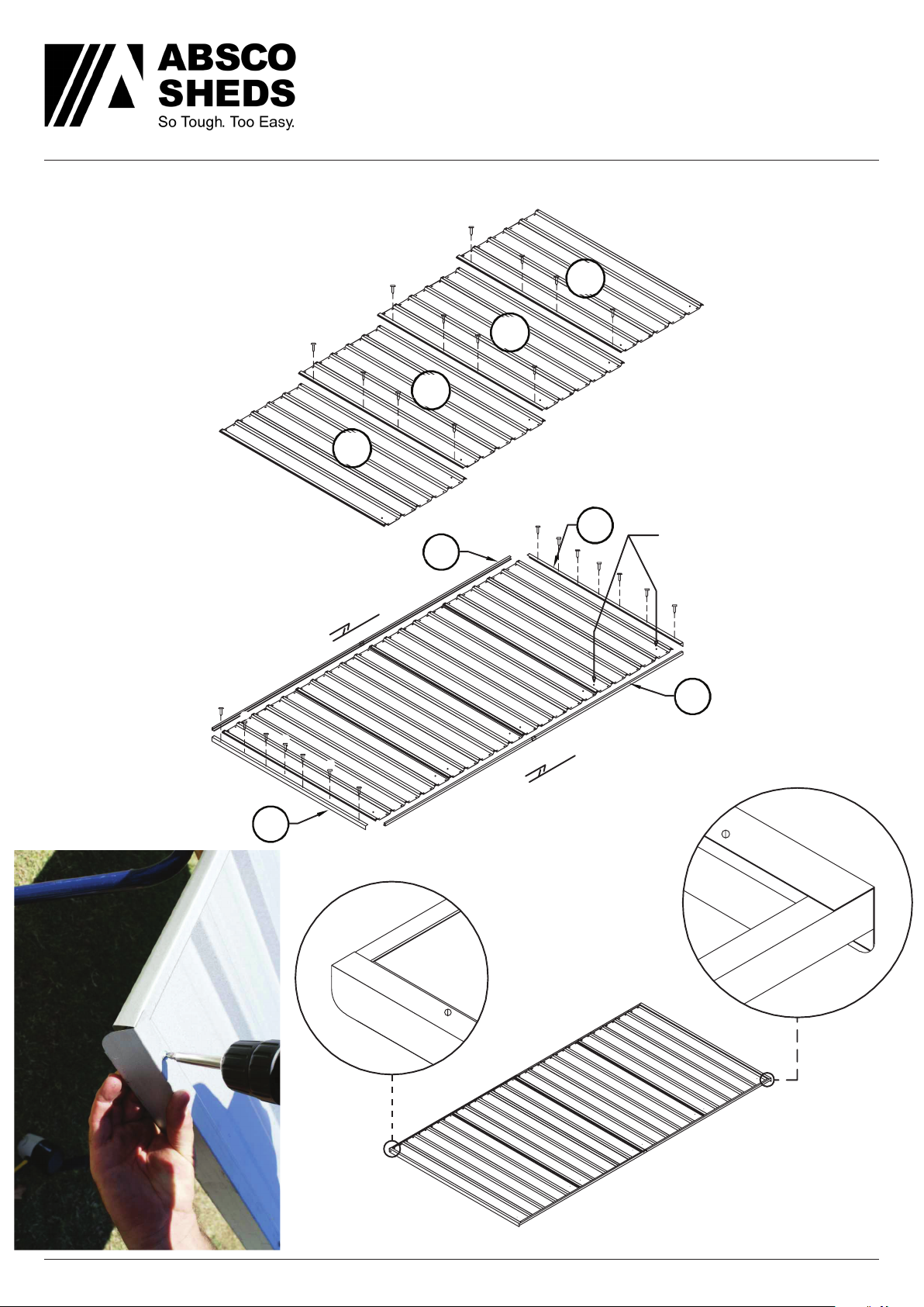
ROOF PANEL ASSEMBLY
2x required.
ABSCO PREMIER SHED
MODEL: 30302GK
3.00mW x 3.00mD x 2.10mH
45A
45A
45A
45A
Fit 81A to edge
60A
87A
D
D
of sheet with prepunched holes.
D
D
87A
i
T TE
SNAP
81A
D
i
D
SNAP
T TE
Absco Industries Assembly Instruction Manual
Model: 30302GK 1.20
10/05/19
14
Page 15
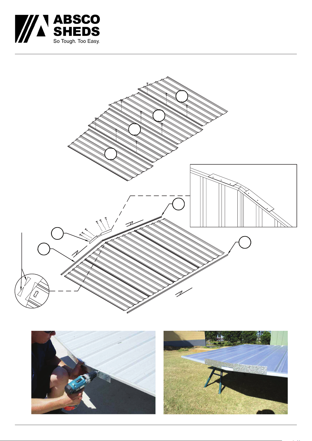
SIDE PANEL ASSEMBLY
2x required.
Trim the tip of each
sheet or bend out of the
way to allow channels to
fit hard up to the edge of
the sheet.
ABSCO PREMIER SHED
MODEL: 30302GK
3.00mW x 3.00mD x 2.10mH
36R
38R
38L
36L
84R
T TE
i
SNAP
INSID
E
O
F
SHED
84L
15A
SNAP
i
T TE
SNAP
i
T TE
81A
Absco Industries Assembly Instruction Manual
Model: 30302GK 1.20
10/05/19
15
Page 16
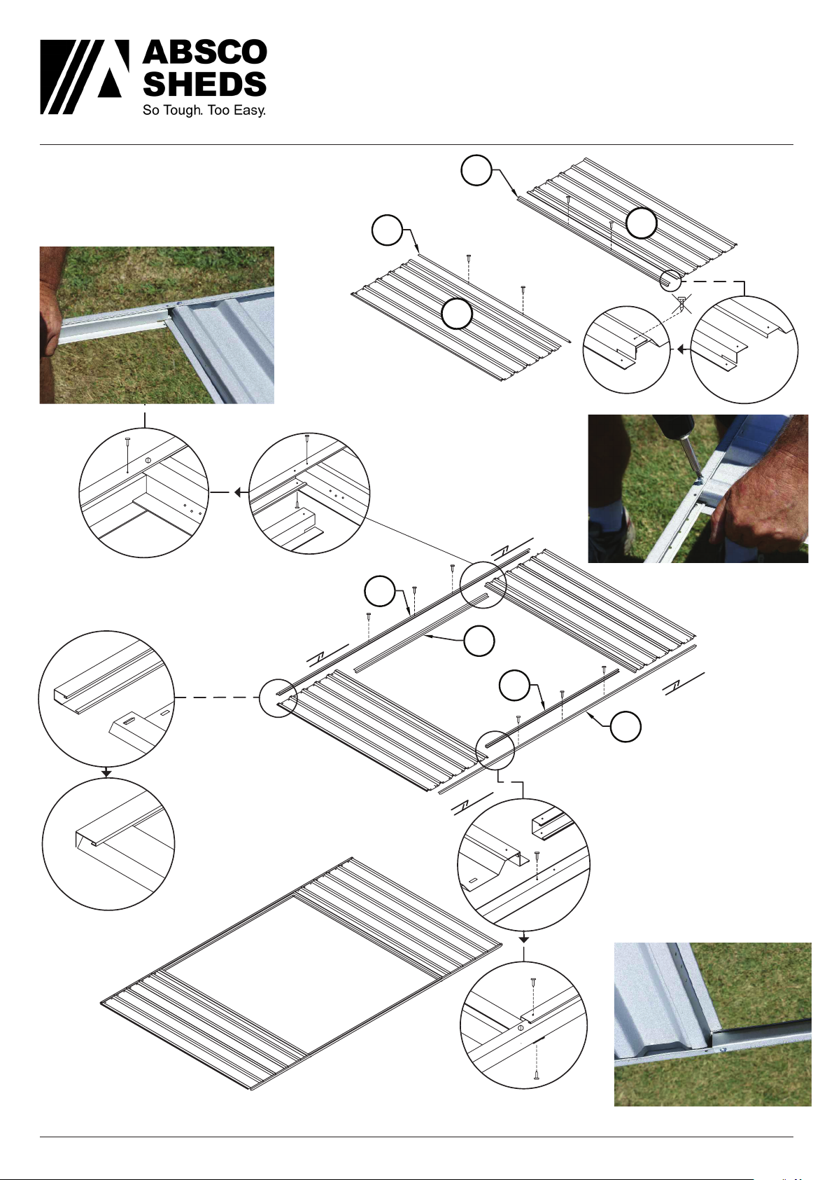
ABSCO PREMIER SHED
MODEL: 30302GK
3.00mW x 3.00mD x 2.10mH
FRONT PANEL ASSEMBLY
1x required.
A
A
5
5
89A
90A
5
5
89A
89A
34A
34A
8
9A
A
0
9
P
i
A
T TE
N
S
55A
i
T TE
SNAP
A
5
5
90A
79A
SNAP
T TE
i
55C
i
T TE
A
5
5
SNAP
89A
79A
5C
5
Absco Industries Assembly Instruction Manual
79A
C
5
5
Model: 30302GK 1.20
10/05/19
16
Page 17

DOOR PANEL ASSEMBLY
ABSCO PREMIER SHED
MODEL: 30302GK
3.00mW x 3.00mD x 2.10mH
1x required.
58C
D
SNAP
D
58C
P
A
TE
N
S
T
i
D
TE
T
i
58A
12A
D
D
D
B
D
D
58B
A
SNAP
T TE
i
58C
58A
Vertical door channels are
installed in the opposite
orientation compared to the
horizontal door channels.
Long
fl ange of
channel
SNAP
T
58C
Short fl ange
of channel
i
TE
89C
B
A
Absco Industries Assembly Instruction Manual
Four hole set for
padbolt connection.
Model: 30302GK 1.20
10/05/19
17
Page 18
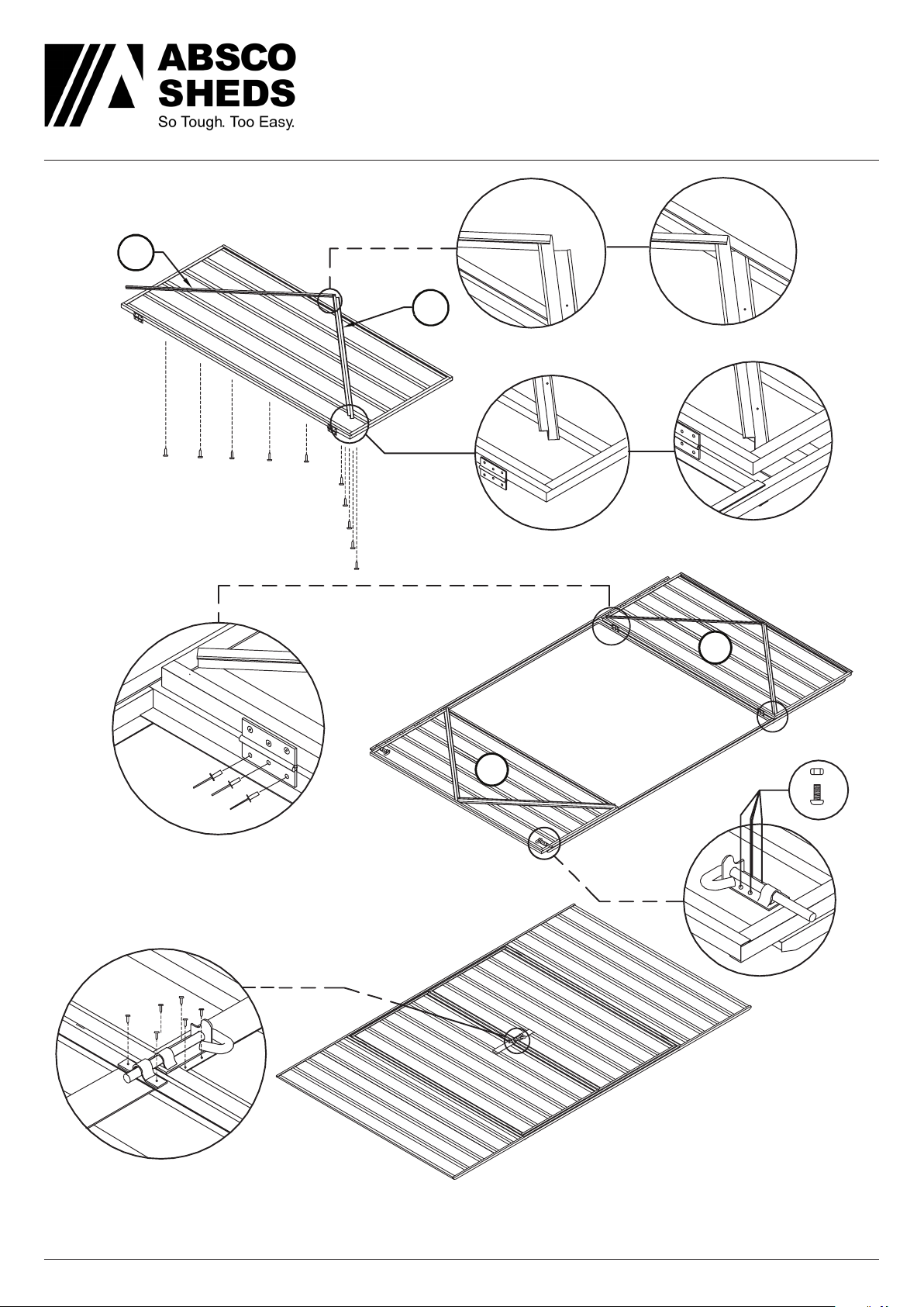
DOOR PANEL ASSEMBLY
91A
ABSCO PREMIER SHED
MODEL: 30302GK
3.00mW x 3.00mD x 2.10mH
91A
Nuts and bolts may be used instead of pop rivets by
drilling out hinge holes using a 4mm drill bit. Both
are supplied.
B
A
The two holes required to connect the padbolt hasp for each door have not been pre-punched, to
allow for proper alignment, position each hasp centrally over the padbolt shaft and drill 3mm holes and
secure with screws.
Absco Industries Assembly Instruction Manual
Model: 30302GK 1.20
10/05/19
18
Page 19

PANEL CONSTRUCTION
ABSCO PREMIER SHED
MODEL: 30302GK
3.00mW x 3.00mD x 2.10mH
NOTE: Take care to ensure that all wall panels
are not upside down. The top channels
of each panel are pre-punched for
attaching roof sheeting. The
base channels are not prepunched.
D
D
D
Side wall channels
fit into the
notched rear wall
channels.
D
D
D
D
D
D
D
D
D
Orient panel so
channel (60A)
goes into ridge
beam
97A
D
D
D
D
D
D
D
D
D
D
Channel (81A)
this end
Pre-punched holes in roof panel to this side
for connection to front and rear walls.
Pre-punched
channel to
match ridge
beam holes
Absco Industries Assembly Instruction Manual
Model: 30302GK 1.20
10/05/19
19
Page 20

ABSCO PREMIER SHED
MODEL: 30302GK
3.00mW x 3.00mD x 2.10mH
INSIDE VIEW OF FIXING
Secure peak brace to
ridge beam and roof
panel with one screw at
each end
Move the other roof
panel into position and
secure peak brace to
ridge beam with one
screw at each end
Absco Industries Assembly Instruction Manual
Model: 30302GK 1.20
10/05/19
20
Page 21
ABSCO PREMIER SHED
MODEL: 30302GK
3.00mW x 3.00mD x 2.10mH
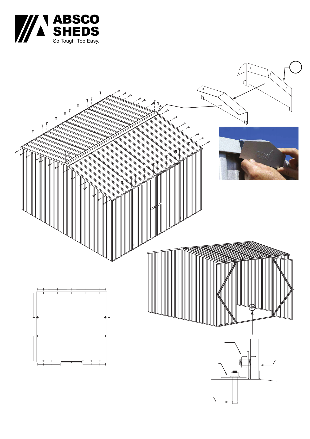
FINAL CONSTRUCTION
D
D
D
14A
D
D
D
D
D
Bend the top and bottom flanges
as shown, then hook the bottom
flanges under the top channel
and screw top to the ridge beam
with two screws.
1000
250250
600
600
600
600
250
1000
ANCHORING OF
SHED
Location of 15
concrete anchors
1000
360
360
360
360
1000
250
Each anchor consists of one nut, bolt, M10
dynabolt and steel angle.
Drill a 10mm hole into the wall sheet.
Drill a 10mm hole into the concrete.
Absco Industries Assembly Instruction Manual
Bolt and Nut*
M10 4.6/S
Steel Angle*
35 x 35 x 3
M10 Dynabolt*
Slab
* Denotes hot dip galvanised fi nish
Model: 30302GK 1.20
10/05/19
Wall Sheet
21
Page 22

ABSCO PREMIER SHED
MODEL: 30302GK
3.00mW x 3.00mD x 2.10mH
Absco Gable Roof Shed Notes
General
• 1.G This instruction manual shall be read in conjunction with other consultants drawings, specifi cations and
written instructions provided by Absco and/or their representatives.
• 2.G The drawings provided herein are for installation and structural engineering purposes only.
• If discrepancies are discovered within the documentation provided, these shall be brought to the attention
of Absco and written approvals obtained prior to commencing the affected section of work.
• 3.G If in doubt ask.
• 4.G Until approvals from the local authorities are obtained, commencement of construction from these
drawings shall not commence.
• 5.G Unless varied by the project specifi cation, all materials and workmanship shall be undertaken in
accordance with the relevant Australian standards and the by-laws and ordinances of the relevant building
authorities.
• 6.G All dimensions indicated in these drawings shall be verifi ed on site by the installation contractor. Scaling
of drawings shall not be undertaken.
• 7.G Prior to commencing works on site, the contractor shall verify the position of all services in the area to
ensure that the construction does not interfere with any of those services.
• 8.G During installation on site the shed structures shall be maintained in a stable condition with no part
becoming overstressed or permanently deformed.
• 9.G In circumstances where the shed has been installed in a manner which is inconsistent with the installation
manual, structural certifi cation shall be void.
• 10.G The structural components detailed within this installation manual have been designed for the following
loads in accordance with AS/NZS1170 based on a Class 10a, Type 2 structure:
• Roof Live Load: 0.25 kPa uniformly distributed or 1.1 kN concentrated as per AS/NZS1170.1
• Wind Load: Classifi cation N2, Non-Cyclonic to AS4055 where Vu = 40 m/s, Vs = 26 m/s
Windward wall Cpe = 0.7
Leeward Wall Cp,e = -0.3 to -0.5 as applicable based on shed geometry
Side Wall Cp,e = -0.5 to -0.65 as applicable based on shed geometry
Roof Cp,e = -0.5 to -1.3 depending on wind direction
6-12 Activity St, Acacia Ridge QLD 4110
PO Box 119, Acacia Ridge QLD 4110
Absco Industries Assembly Instruction Manual
AU: 1800 029 701
N Z: 0800 466 444
Model: 30302GK 1.20
[email protected]
www.abscosheds.com.au
10/05/19
22
Page 23
ABSCO PREMIER SHED
MODEL: 30302GK
3.00mW x 3.00mD x 2.10mH
Absco Gable Roof Shed Notes
Steelwork
• 1.S All structural steelwork shall have a corrosion protection system applied consistent with AS/NZS 2312-
2002.
• 2.S All structural steelwork detailed within this installation manual shall be minimum Grade
• 550 for roll formed sections (including roof and wall sheeting) and Grade 250 for angle sections.
• 3.S All roof, and wall sheeting shall be minimum base metal thickness of 0.3mm
• 4.S All snaptite channels and jambs shall be minimum base metal thickness of 0.42mm
• 5.S All top hats shall be minimum base metal thickness of 1.0mm
• 6.S All screw fasteners shall be Phil Pan Head Zinc Plated #8 x 3/4” (STP0820)
• 7.S All bolt fasteners for anchoring shall be M10 minimum grade 4.6/S
• 8.S Installation of screw fasteners shall generally be undertaken in accordance with the relevant provisions
of AS1562.
Supporting Slab and Foundations
• 1.F The supporting slab foundation for the garden shed shall be of a minimum size indicated on the installation
manual. The top surface of the formed slab shall be level and free of any irregularities which would inhibit
the installation of the shed.
• 2.F The structural engineering design for the supporting slab foundation shall be undertaken by a suitably
qualifi ed structural engineer. The design shall consider all relevent provision of AS3600 and AS2870.
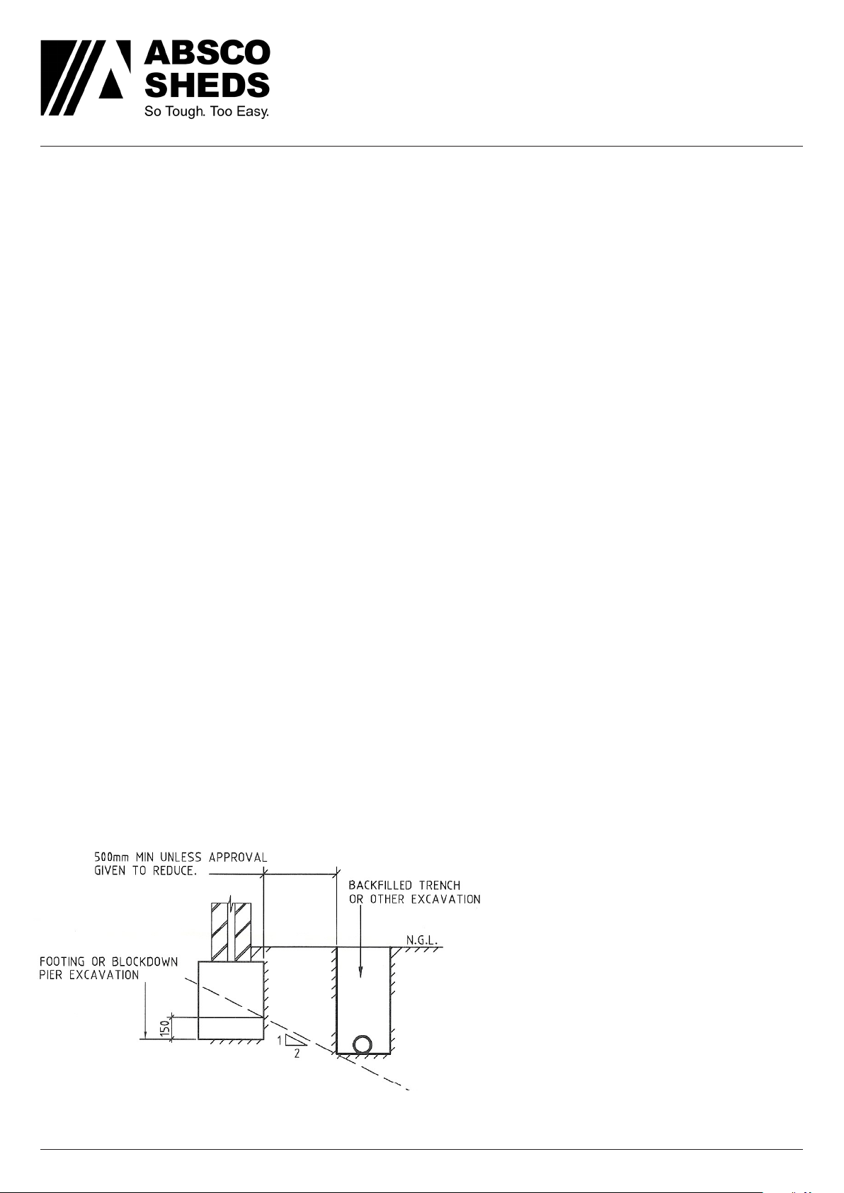
• 3.F Between adjacent footings or excavations, the contractor installing the slab foundation shall not exceed
a rise of 1 in a run of 2 in line of slope.
• 4.F Unless approved in writing by the slab foundation engineer, the limits of excavations near existing
footings shall be in accordance with that indicated below.
The contactor shall undertake investigatory
localised excavations near existing
footings to ascertain their depth prior to
excavating adjacent to them. It is noted that
excavating to a depth below that indicated
above shall not be undertaken without
the written approval from the engineer.
Absco Industries Assembly Instruction Manual
Model: 30302GK 1.20
10/05/19
23
Page 24

ABSCO PREMIER SHED
MODEL: 30302GK
3.00mW x 3.00mD x 2.10mH
Absco Sheds Storage Guidelines
• Absco Sheds are designed to be weatherproof for normal weather conditions. In the event of extreme
weather conditions such as heavy rain, combined with high wind gusts, the ridge capping, sheeting joins,
screw fi xings etc., may exhibit minor deformations which may allow some water entry. These areas should be
checked regularly to ensure that maximum strength and protection is maintained.
• Other weather conditions such as extreme heat and extreme cold, moist or dry air can infl uence the effects
of concrete fl oor moisture and/or condensation on the underside of the roof sheets.
• Absco Sheds and storage units are primarily used for storage of garden equipment such as lawnmowers,
wheelbarrows, garden tools etc. Storage items that might be adversely affected by any of the above conditions
may require additional protection such as being sealed or covered by plastic sheets and/or stacked above
the concrete fl oor on timber slats.
• Waterproof sealants may be used to offer further protection where required around joins and screw fi xings,
as can rubber door seals and other products which are available from most hardware outlets.
• Placement of waterproof sealants (silicone) between the base of the shed and concrete slab is not
recommended, as this process can have a reverse effect, preventing excess water from escaping, resulting
with water accumulating and being trapped inside the shed.
• Absco accepts no responsibility for water entry, fl oor moisture, condensation or the condition of the Contents
inside your Absco steel building arising from any of the pre-mentioned weather conditions.
6-12 Activity St, Acacia Ridge QLD 4110
PO Box 119, Acacia Ridge QLD 4110
Absco Industries Assembly Instruction Manual
AU: 1800 029 701
N Z: 0800 466 444
Model: 30302GK 1.20
[email protected]
www.abscosheds.com.au
10/05/19
24
Page 25

Lifetime Warranty Statement
This warranty against defects is given by:
Absco Industries (ABN: 77 869 708 678)
Address: PO Box 119 Acacia Ridge QLD 4110
Ph: 1800 029 701
Fax: 07 3344 1191
Email: [email protected]
Date of issue: 19 December 2018
Details of Manufacturer’s Warranty
This product comes with a Lifetime structural warranty from the date of purchase. This warranty also
applies where there are missing or damaged parts identi ed in the parts list referred to in the instruction
kit within the product packaging.
Please ensure that you keep this warranty form in a safe place along with your proof of purchase. You can
register your warranty online http://abscosheds.com.au/warranty-details/ or complete the form on the
back of this document and mail it back to Absco, along with a copy of your proof of purchase.
The bene ts of this warranty are in addition to your rights under the Australian Consumer Law (ACL) and
in particular, the guarantees implied under the ACL and any other rights and remedies of the consumer
under a similar law in relation to the goods and services to which this warranty relates.
Process of claiming warranty:
To make a claim under the warranty within the warranty period, you will need to contact the manufacturer
directly by phone or email:
Contact Number: 1800 029 701
Contact Email: [email protected]
You will be required to produce proof of purchase (this is at discretion of the manufacturer) at the time of
the claim.
The manufacturer bears the cost of replacing the products or spare parts or repairing the products and
reasonable direct expenses of claiming under this warranty:
Where parts are replaced, the manufacturer will bear the cost of sending the spare part and will endeavour
to deliver it to the customer’s nearest reseller within 20 working days for the customer to pick up. At such
time the customer may be required to return the alleged faulty parts.
Where assessment is required in case of replacing or repairing the product, the manufacturer will appoint
an assessor within 10 working days to identify the alleged defect. The manufacturer will bear the repair
costs by appointing a local tradesman. The manufacturer may choose to replace the product if the repair or
the cost of repair is not feasible. The replacement product will be available for collection from the nearest
reseller within 20 working days. The customer will bear the cost of assembly for the replacement product.
1
Page 26

IMPORTANT
1. Manufacturer’s Disclosure
This warranty against defects shall not apply in the following situations:
A) Where the product is not assembled in accordance with the instructions provided in the product kit;
B) Where the product is used to store corrosive materials such as fertilizer, chlorine etc;
C) The warranty does NOT cover damage caused by storms, wind, rain, snow or poor foundations;
D) This warranty does not apply to surface deterioration of panels caused by ‘Swarf’ (Tiny particles of
steel debris left from cutting, grinding or drilling operations) that has not been removed after building
construction.
2. Notes
This product is weatherproof to a certain level; however driving windy rain may cause the product to leak.
Condensation may also occur in some weather conditions such as extreme heat or cold. The product
should only be used for storing items such as gardening equipment and should not be used for articles
that may be prone to damage if they come into contact with moisture.
We recommend you use a waterproof sealant to ll any gaps or joins in order to minimise the risk of water
entering.
3. Major Defects
If the manufacturer is satis ed that the defect is a major defect, the purchase price may be refunded in lieu
of providing a replacement product or repairing the product.
This warranty is provided in addition to other rights and remedies you have under law: Our goods come
with guarantees which cannot be excluded under the Australian Consumer Law. You are entitled to
replacement or refund for a major failure and to compensation for other reasonably foreseeable loss or
damage. You are also entitled to have the goods repaired or replaced if the goods fail to be of acceptable
quality and the failure does not amount to a major failure.
If you do not wish to register your warranty online, complete the below form and email, fax or
post this form back to Absco, along with a copy of your proof of purchase.
NAME:
STREET ADDRESS: POSTAL / ZIP CODE:
STATE / CITY / PROVINCE / REGION:
COUNTRY:
SHED TYPE/CODE:
ORDER NO:
DATE OF PURCHASE:
EMAIL ADDRESS:
DATE REGISTERED:
2
 Loading...