


Corrigo manual
Ventilation application
© Copyright AB Regin, Sweden, 2013

DISCLAIMER
The information in this manual has been carefully checked and is believed to be correct. Regin however , makes no warranti es
as regards the contents of this manual and users are requested to report errors, discrepancies or ambiguities to Regin, so that
corrections may be made in future editio ns. The information in this document is subject to change without prior notification.
The software described in this document is supplied under licence by Regin and may be used or copied only in accordance
with the terms of the licence. No part of this document may be reproduced or transmitted in any form, in any fashion,
electronically or mechanically, without the express, written permission of Regin.
COPYRIGHT
AB Regin. All rights reserved .
TRADEMARKS
Corrigo, E tool
©
, EXOdesigner, EXOreal, EXOrealC, EXOline, EXO4, EXO4 Web Server, Optigo, Regio and Regio tool are
registered trademarks of AB Regin.
Windows, Windows 2000, Windows XP, Windows Vista, Windows 7, Windows 8 and Windows Server 2003 are registered
trademarks of Microsoft Corporation.
Some product names mentioned in this document are used for identification purposes only and may be the registered
trademarks of their respective companies.
Revision R, September 2013
Software revision: 3.3

Table of contents
CHAPTER 1 ABOUT THE MANUAL .................................................................................................. 6
More information ........................................................................................................................ 6
CHAPTER 2 ABOUT CORRIGO ......................................................................................................... 7
2.1 News in version 3.3 ................................................................................................................ 7
2.2 Application choice ................................................................................................................. 7
2.3 Technical data ...................................................................................................................... 12
CHAPTER 3 INSTALLATION AND WIRING ...................................................................................... 14
3.1 Installation ........................................................................................................................... 14
3.2 Wiring .................................................................................................................................. 14
CHAPTER 4 COMMISSIONING ...................................................................................................... 21
4.1 How to do it ......................................................................................................................... 21
CHAPTER 5 FUNCTIONAL DESCRIPTION ....................................................................................... 24
5.1 Temperature control ........................................................................................................... 24
5.2 Extra control circuit ............................................................................................................. 37
5.3 Humidity control .................................................................................................................. 38
5.4 Fan control ........................................................................................................................... 39
5.5 Pump control ....................................................................................................................... 45
5.6 Damper control .................................................................................................................... 45
5.7 Extended running and External switch ................................................................................ 46
5.8 Time-switch outputs ............................................................................................................ 47
5.9 Alarms .................................................................................................................................. 47
CHAPTER 6 STARTING AND STOPPING THE UNIT ......................................................................... 49
6.1 Start conditions .................................................................................................................... 49
6.2 Stop conditions .................................................................................................................... 49
6.3 Start sequence ..................................................................................................................... 50
6.4 Stop sequence ..................................................................................................................... 50
CHAPTER 7 DISPLAY, LEDS AND BUTTONS ................................................................................... 51
7.1 Display ................................................................................................................................. 51
7.2 LEDs ..................................................................................................................................... 51
7.3 Buttons ................................................................................................................................ 51
7.4 Navigating the menus .......................................................................................................... 51
CHAPTER 8 ACCESS RIGHTS .......................................................................................................... 53
8.1 Log on .................................................................................................................................. 53
8.2 Log off .................................................................................................................................. 53
8.3 Change password ................................................................................................................. 54
8.4 Change password to remove automatic logoff ................................................................... 54
CHAPTER 9 RUNNING MODE ....................................................................................................... 55
9.1 Running mode, unit ............................................................................................................. 55
9.2 Selected functions ............................................................................................................... 55
9.3 Alarm events ........................................................................................................................ 56
9.4 Inputs/Outputs .................................................................................................................... 56
CHAPTER 10 TEMPERATURE ........................................................................................................ 57
CHAPTER 11 AIR CONTROL........................................................................................................... 62
CHAPTER 12 HUMIDITY CONTROL................................................................................................ 65
CHAPTER 13 TIME SETTINGS ........................................................................................................ 66
13.1 Time / Date ........................................................................................................................ 66
13.2 Timer Normal speed .......................................................................................................... 66
13.3 Timer Reduced speed ........................................................................................................ 67

13.4 Extended running .............................................................................................................. 67
13.5 Timer outputs 1…5 ............................................................................................................. 67
13.6 Holidays ............................................................................................................................. 68
CHAPTER 14 MANUAL / AUTO ..................................................................................................... 69
CHAPTER 15 SETTINGS ................................................................................................................. 72
15.1 Control temp ...................................................................................................................... 72
15.2 Control pressure ................................................................................................................ 73
15.3 Control flow ....................................................................................................................... 73
15.4 Humidity control ................................................................................................................ 74
15.5 Control Extra unit ............................................................................................................... 74
15.6 Alarm settings .................................................................................................................... 74
15.7 Save and restore settings................................................................................................... 76
CHAPTER 16 EXPANSION MODEL ................................................................................................. 77
16.1 Ports ................................................................................................................................... 77
16.2 Wiring ................................................................................................................................ 77
CHAPTER 17 CONFIGURATION ..................................................................................................... 79
17.1 Inputs and outputs............................................................................................................. 79
17.2 Sensor settings ................................................................................................................... 81
17.3 Control function ................................................................................................................. 82
17.4 Fan control ......................................................................................................................... 82
17.5 Extra control circuit ........................................................................................................... 83
17.7 Extra sequence Y5 .............................................................................................................. 84
17.8 Heating coil ........................................................................................................................ 84
17.9 Exchanger .......................................................................................................................... 84
17.10 Chiller ............................................................................................................................... 85
17.11 Pump control ................................................................................................................... 86
17.12 Free cooling ..................................................................................................................... 86
17.13 Support control ................................................................................................................ 87
17.14 CO2 Demand control ........................................................................................................ 87
17.15 Fire function ..................................................................................................................... 87
17.16 Humidity control .............................................................................................................. 88
17.17 Exchanger de-icing ........................................................................................................... 88
17.18 Cooling recovery .............................................................................................................. 88
17.19 Minimum limit dampers .................................................................................................. 88
17.21 External setpoint .............................................................................................................. 89
17.22 Run indication / Motor protection .................................................................................. 89
17.23 Actuator type ................................................................................................................... 90
17.24 Running time, 3-position actuators ................................................................................. 90
17.25 Step controllers ................................................................................................................ 91
17.26 Recirculation .................................................................................................................... 92
17.27 Pretreatment ................................................................................................................... 93
17.28 Alarm setting ................................................................................................................... 93
17.29 Communication ............................................................................................................... 97
17.30 Other parameters ............................................................................................................ 99
17.31 System ........................................................................................................................... 102
CHAPTER 18 OTHER FUNCTIONS ................................................................................................ 105
18.1 Alarm handling ................................................................................................................. 105
18.2 Free text ........................................................................................................................... 105
18.3 Revision number .............................................................................................................. 105
18.4 Language .......................................................................................................................... 106
18.5 Indication LEDs ................................................................................................................ 106
18.6 Changing the battery ....................................................................................................... 106
18.7 Start-up wizard ................................................................................................................ 107
18.8 Energy calculation ............................................................................................................ 109
18.9 SFP (Specific Fan Power) .................................................................................................. 109

INDEX ........................................................................................................................................ 110
APPENDIX FREQUENCY CONVERTERS ........................................................................................ 114

6 Chapter 1 About the manual Manual Corrigo Ventilation, revision R
Chapter 1 About the manual
This manual co vers all t he models in the Corrigo ser ies used with the ventilation app lication. This
revision covers program revisions from 3.3.
More information
More information about Corrigo can be found in:
• Corrigo ventilation user guide – A simplified manual
• Manual E tool
©
– Manual on how to configure the controllers using t he PC software
E tool
©
, available i n Swedish, English, German and French.
• LON-interface variable list – Variable list for the Corrigo series, available in Swedish and
English.
• Corrigo ventilation variables for EXOline, Modbus and BACnet – Variable list for
EXOline, BACnet and Modbus communication, available in Engli sh.
• Corrigo ventilation Communication Guide – The most common Modbus and BACnet
variables.
• Editable PDF files for Co rrigo
• CE - Declaration of conformity, Corrigo
The information is available for download from Regin's website, www.regin.se
.

Manual Corrigo Ventilation, revision R Chapter 2 About Corrigo 7
Chapter 2 About Corrigo
The Corrigo series comprises three model sizes: 8, 15 or 28 in-/outputs.
In each third generation model Corrigo, all applications are loaded in a separate memory area. The
models have article number E...-3 (where 3 sta nds for third ge neration). A ne w feature in ver sion
3.3 are models with three communication ports. The 3 port Corrigo models have article number
E...3-3 (where the initial “3” stands for 3 ports). For more detailed information, see chapter 16.
The controllers are available with or without a front panel display and buttons. For all third
generation units, both with a nd without display, a separate, cable-connected terminal E3-DSP with
display and buttons is available.
All configuration and normal handling can be done using the display and buttons or using the
configuration tool E tool
©
, installed on a PC and connected via the communication cable E-cable.
2.1 News in version 3.3
• The operating system has been further improved and is now called EXOrealC.
• Support for three communication ports.
• BACnet/IP is now available as a communication protocol.
• New filter alarm: Separate filter alarms.
• Analogue filter alarm, filter pressure alarm.
• Temperature alarm for extra sensors 1-5.
• Support for 0…10V outdoor sensor and room sensor.
• Modulating recirculation air damper, Y4-Extra sequence.
• Communication with Danfoss model Frequency converters FC 101 now supported.
• Additional Modbus signals.
2.2 Application choice
On deliver y, t he ma i n me mor y i n the Corrigo is empty. All t he a p pl ic ati o n p r o grams that can b e ru n
in the Corrigo are located in a separate memory area.
On the first start-up, the controller will start a special program for downloading a suitable
application and suitable languages to the main memory.
For certain customised models, an application has already been selected when the product is
delivered. If so, the selected application will be started immediately.
E283W-3
PLA: 254 ELA: 30
Baud#1: 9600
Rev: 3.3-1-01
The initial screen details the model of the Corrigo unit, its communication address, communication
speed and which software revision is loaded into the unit.
Press down arrow to go to ”Application choices”.
Application
System
Communication
Time/Date
Input/Output

8 Chapter 2 About Corrigo Manual Corrigo Ventilation, revision R
Use the up and d own arrows to move the cursor in the left edge of the display to the function you
wish to select. Select “Application” and press the right arrow.
Corrigo Vent.131021
Expansion unit 1
Expansion unit 2
Corrigo Vent.140212
Move the cursor to the desired application. Press the right arrow.
Title:
Corrigo Ventilation
3.3
Activate? No
Press ”OK” and change ”No” into ”Yes”. Press ”OK”.
The most recently loaded ventilation ap plication will now be entered into memory. T his will take
approx. 30 seconds. The application start screen is displayed.
To change lang uages, press th e r ight ar r o w 3 ti me s a nd t he n cho o se a l ang uage i n the sa m e wa y you
selected an application.
2.2.1 Additional menu options
System:
Information on the Corrigo model and serial number.
EXOreal version.
MAC address and IP address.
Battery status and memory size.
Memory status and voltage frequency.
Communication:
Communication mode selection.
Serial:
Enables selecting EXOline address, communication speed, port mode and routing span.
TCP/IP:
Enables EXOline address selection and choice of DHCP (Yes/No).
Also enables manual IP address and subnet mask setting before the Corrigo is initiated. Default
Gateway and DNS name is also available under this menu.
Current sub net mask, gateway and DNS name.
Main computer status.
Main computer IP address.
Permit connection to main computer.
TCP port routing to serial port 1 or 2.
Time/Date:
Permits setting the time and date.

Manual Corrigo Ventilation, revision R Chapter 2 About Corrigo 9
Input/Output:
Enables In-/Output reading and writing.
2.2.2 Ventilation applicati on
The temperature controller is based on a supply air PI-controller for heating control with a preprogrammed set of control modes. A number of different control functions as well as analogue and
digital in- and output functions can be bound to this controller. Certain functions are necessary,
while others can be considered optional. The choice of which functions are to be used is free, the
only restriction is the physical number of inputs and outputs of the different models. The maximum
number of I/Os is 3*28 (a 2- or 3-port Corrigo with two expansion units).
The Corrigo is designed for DIN-rail mounting.
The program for an air handl ing unit conta ins, apart from other things, the following functions :
Different temperature control modes :
• Supply air temperature control, with or without outdoor temperature compensation
• Room temperature control (cascade control).
• Extract air control (cascade control).
• Seasonal switching between supply air temperature control and room/extract air
temperature control.
• Outdoor compensated room/extract air control.
• Extra, separate temperature control circuit for after-heaters, etc.
• Extra control sequences Y4 and Y5 (in addition to Y1, Y2 and Y3) for free integration
into the controller output.
With control of:
• Heat exchanger (liquid connected, plate or rotating) or mixing dampers.
• Heating coil: Water with or without frost protection or electric with high te mperature limit
switch.
• Cooling: Water or DX cooling in up to 3 steps.
• Circulatio n pumps heating, cooling, exchanger.
Fan control
• 1- or 2-speed supply air and extract air fans.
• Frequency controlled supply and extract air fans with pressure or flow control, manual
control or external control from a VAV sys tem.
• Pressure controlled supply air fan with slave connected extract air fan (output dependent or
flow dependent) or opposite function (pressure controlled extract air fan with slave
connected supply air fan, output dependent or flow dependent).
Humidity control
It is possible to use either humidification or dehumidification, or to use combined humidification
and dehumidification.
Timer control
For starting and stopping the unit, annual clock function. Up to 5 timer outputs for control of
external func tions such as lighting, doorlocks etc.

10 Chapter 2 About Corrigo Manual Corrigo Ventilation, revision R
Demand controlled ventilation
In building s with strongl y varying occup ancy the fa n speeds or mixi ng dampers can be controlled
by the air quality measured by a CO
2
sensor.
Support control
When using the control funct ion room control or extract air temperature contro l, it is possible to
utilise support-heating and/or support-cooling.
Free cooling
When this function has been activated, it is used durin g the summer to cool the building durin g the
night using c ool outdoor air thereby reducing the need to run chillers during the day.
Free heating
If the outdoor temperature is higher than the indoor temperature and there is a heating demand, the
recovery damper will not open for recovery but instead open fully for outdoor air. This may occur
during low night-time outdoor temperatures, when the room has been cooled considerably and the
outside heat is rising faster than indoors. This function is activated at the same time as “Free
cooling”.
Enthalpy control
Measures and compares the energy content (enthalpy) of the outdoor air and the extract air
(temperature and air humidity). When this function is active, the mixing damper signal will be
overridden to recirculation if the enthalpy is higher outdoors than indoors.
Pretreatment
Damper and pump control for preheating or precooling of the outdoor air via an underground intake
channel.
Cooling recovery
If the extract air is colder than the outdoor air and cooling is required, the heat exchanger control is
reversed in order to return the cool extract air.
Recirculation control
Recirculation of air using a supply air fan and (optionally) extract air fan and a recirculation damper
with or witho ut temperature co ntrol. Used as a recove ry function or duri ng heating with supp ort
control during the night. Recirculation control is available as an analogue or a digital function.
Step controllers Heating/Cooling
As an alternative to the analogue control of ”Actuator heating Y1” or ”Actuator cooling Y3” step
controllers can be used for controlling hea ting or cooling in steps using digital contro l.
Change-over
In 2-pipe systems where a combination heater/cooler is operating together with a heat pump,
Change-over is a funct ion tha t ena bles usi ng the sa me pi pe for both heat ing and c ooli ng, dep ending
on which is currently requi red. It uses t he output Y1 Hea ting/Y3 Co oling.
Manual Corrigo Ventilation, revision R Chapter 2 About Corrigo 11
Corrigo hardware overvi ew
E81-3
E81D-3
E151-3
E151W-3
E151D-3
E151DW-3
E15D-S-LON
E152W-3
E152DW-3
E281-3
E281D-3
E281W-3
E281DW-3
E282W-3
E282DW-3
E28D-S-LON
E283W-3
E283DW-3
AI*
2 2 4 4 4 4 4 4 4 4 4 4 4 4 4 4 4 4
DI*
3 3 4 4 4 4 4 4 4 8 8 8 8 8 8 8 8
8
UI*
-
- - - - - -
- - 4 4 4 4 4 4 4 4 4
AO*
1 1 3 3 3 3 3 3 3 5 5 5 5 5 5 5 5 5
DO*
2 2 4 4 4 4 4 4 4 7 7 7 7 7 7 7 7
7
RS485
•
• •
•
• • • • •
• • • • •
BACnet/IP
• • • • • • • • •
•
LON
•
•
TCP/IP
•
•
• • • • • • • •
1 port
• • • • • • • • • • •
2 ports
• • • • •
3 ports
•
•
Display
•
•
• •
• •
•
• •
•
* AI=analog ue inputs, DI= digital inputs, A O=analogue out puts, DO=digita l outputs, UI= universal
inputs (can be configured to function a s either analogue input or digital input).
All third generation Corrigo contro lle r s support external displays.
Corrigo model overview
Models with dis play Models without display Description
E81D-3
E151D-3
E281D-3
E81-3
E151-3
E281-3
Standard controller with RS485 port
E15D-S-LON
E28D-S-LON
Controller with both LON an d RS485 port
E151DW-3
E281DW-3
E151W-3
E281W-3
Controller with TCP/IP port and built-in web server
E152DW-3
E282DW-3
E152W-3
E282W-3
Controller with one RS485 port, one TCP/IP port and
built-in web serv er
E283DW-3 E283W-3
Controller with two RS485 ports, one TCP/IP port
and built-in web server

12 Chapter 2 About Corrigo Manual Corrigo Ventilation, revision R
2.3 Technical data
Protection class .................................................................................................................. IP20
Display........................................................ 4 rows of 20 characters. Background illumination.
LEDs
Yellow ....................................................................................................... Settable parameter
Red ............................................................................................................... Alarm indication
Clock .................................................................. Year base 24 hour clock with battery backup.
Automatic summer-/winter-time changeover.
Operating sys te m .......................................................................................................... EXOreal
Supply voltage .................................................... 24 V AC ±15%, 50…60 Hz or 21…36 V DC
Power consumption ........................................ 5 VA, 3 W (DC), model …W: 9 VA, 5 W (DC)
Dimensions .................................................................... 148x123x60 (WxHxD incl. terminals)
Casing .......................................................................... Standard Euronorm (8.5 modules wide)
Mounting ................................................................................................................ On DIN-rail
Operation
Climatic conditions according to IEC 721-3-3 ........................................................ Class 3k5
Ambient temperature ..................................................................................................0...50°C
Ambient humidity .............................................................................................. Max 95% RH
Mechanical requirements according to IEC721-3-3 .............................................. Class 3M3
Vibration .......................................................... IEC60068-2-6, Test FC, vibration Sinusoidal
Shock ................................................................................................ IEC60068-2-27, Tes t Ea
Transport
Climatic conditions according to IEC 721-3-2 ........................................................ Class 2k3
Ambient temperature .............................................................................................. -20...70°C
Ambient humidity .............................................................................................. Max 95% RH
Mechanical requirements according to IEC721-3-2 .............................................. Class 2M2
Vibration .......................................................... IEC60068-2-6, Test FC, vibration Sinusoidal
Shock ................................................................................................ IEC60068-2-27, Tes t Ea
Free fall .............................................................................................IEC60068-2-27, Test Ed
Storage
Climatic conditions according to IEC 721-3-1 ........................................................ Class 1k3
Ambient temperature .............................................................................................. -20...70°C
Ambient humidity .............................................................................................. Max 95% RH
Battery
Type .................................................................................... Replaceable Lithium cell, CR2032
Battery life ................................................................................................... Better than 5 years
Warning .................................................................................................... Low battery warning
Battery backup ............................................................................... Memory and real time clock
Communication
EXOline Port 1, insulated via a b uilt-in RS485 contact.
EXOline Port 2, via a built-in RS485 contact.
EXOline TCP/IP.
Modbus communication via serial RS485 communication (not TCP/IP).
BACnet/IP.
LON serial communication.
Suitable model should be selected for appropriate needs.
EMC emission and immunity standard
This product conforms to the requirements of the EMC Directive 2004/108/EC through product
standards EN 61000-6-1 and EN 61000-6-3.
RoHS
This product conforms to the Directive 2011/65/EU of the European Par lia ment and of the Council.

Manual Corrigo Ventilation, revision R Chapter 2 About Corrigo 13
Inputs
Analogue inputs AI .............................................. Settable 0…10 V DC or PT1000, 12 bit A/D
Digital inputs DI ....................................................................................... Potential-free closure
Universal inputs UI ........................................... Can be set to act as either an a nalogue input or
a digital input with specifications as above
Outputs
Analogue outputs AO ............................................... Configurable 0…10 V DC; 2…10 V DC;
10…0 V DC or 10…2 V DC
8 bit D/A short-circuit protected
Digital outputs DO ........................................... Mo s fet outputs, 24 V AC/DC, 2 A c ontinuous.
Totally max 8 A.
Options
LON ................................................................... FT3150, gives a second communication route
…W (TCP/IP-port) ............................... Replaces RS485 for EXOline (Port 1) communication
2-port Corrigo models ........................ Two serial ports or one serial port and one TCP/IP port
3 ports Corrigo............................................................ .... Two serial ports and one TCP/IP port
External hand terminal, E3-DSP ......................... For use with Corrigo E units wit hout display
External room unit...................................................................... ED-RU / ED-RUD / ED-TCV
Position of the terminals on the Corrigo

14 Chapter 3 Installation and wiring Manual Corrigo Ventilation, revision R
Chapter 3 Installation and wiring
3.1 Installation
Corrigo can be mounted in a DIN-standard casing (minimum 9 modules), on a DIN-rail in a cabinet
or, using a suitable front-mounting kit, in a cabinet door or other control panel.
Ambient temperature: 0…50°C.
Humidity: Max. 90 % RH, non-condensing.
The picture below shows a wiring exa mple for Corrigo E283W-3.
3.2 Wiring
At the end of this chapter there are wiring diagrams showing the factory set configuration. There are
also empty wir ing diagrams. Sinc e the function of most of the inputs and out puts depends on t he
programming of the unit the f inal wiring diagram can not be filled in until the in staller has decided
how to use the inputs/ou tputs. It is impor tant to ensure that the wirin g is performed correctly and in
accordanc e with the instr uctions given in this manual.

Manual Corrigo Ventilation, revision R Chapter 3 Installation and wiring 15
3.2.1 Supply voltage
24 V AC ±15%, 50…60 Hz or 21…36 V DC
If Corrigo and its connected actuators share the same transformer, it is essential that the same
transformer pole is used as reference for all the equipment. The equipment may otherwise not
function as intended and may also suffer damages.
3.2.2 Inputs and outputs
The list of inp ut and outp ut functions in sectio n 3.2.3 is a handy instru ment to help you keep t rack
of which inputs and outputs you will need to configure.
Analogue inputs
Analogue inputs must refer to an Agnd terminal placed in the same terminal block as the input being
wired.
Analogue inputs can, depending on the configuration, be used for either PT1000 temperature
sensors or for 0…10 V DC analogue input signals, for example from a pressure transmitter.
Digital inputs
Digital inputs must refer to +C on terminal 4. Digital inputs may only be wired to voltage-free
contacts. Any external volta ge applied to a digital input ma y harm t he uni t. The input signa l can b e
set to either NO or NC.
Universal inputs
A universal i nput can be co nfigured to act as either an analogue input or as a digital input.
A universal i nput con figured a s an analog ue input c an, dep ending o n the confi guratio n, be used for
either PT 1000 temperat ure sensors o r for 0…10 V DC analogue i nput signal s, for exam ple from a
pressure transmitter.
Universal i nput s co nfig ured as an a nalo gue i npu t must refer to an Agnd terminal placed in the same
terminal block as the input being wired.
A universal input configured as a d igital input must, just like other digital inputs refer to C+ on
terminal 4. It may only be wired to voltage-free contacts.
Analogue outputs
Analogue outputs must refer to the Agnd te rminal placed in the AO terminal block.
All analogue outputs can be individually set to any one of the following signals:
0…10 V DC
2…10 V DC
10…0 V DC
10…2 V DC
If the Corrigo and the actuators connected to it share the same transformer it is essential that the
same transfor mer-pole is used as reference for all the equipment. Failure to do so will prevent the
equipment from functioning as intended and may also lead to damages.
Digital outputs
Digital outputs should normally refer to G
DO
on terminal 10. G
DO
is internally connected to G o n
terminal 1 and supplies 24 V AC or DC depending on the choice of supply voltage.
All the digital outputs are controlle d by MOSFET transistors. The outputs are inter nally connected
with G
0
and can deliver max 2 A per output. However, the total power for all the DOs must not be
over 8 A.

16 Chapter 3 Installation and wiring Manual Corrigo Ventilation, revision R
A number of different wiring alternatives are possible depending on the type of supply voltage to
the Corrigo and the relay type.
24 V AC supply and 24 V AC relays
24 V DC supply and 24 V DC relays
24 V AC supply and 24 V DC relays
G
G
0
10
11
12
L
N
24 V
AC
G
G
0
10
11
12
+
-
24 V DC
+ + + -
G
G0
10
11
12
L
N
24 VAC
24 V DC
+ -
+ -
+ -
+ -
24 V AC
24 V AC

Manual Corrigo Ventilation, revision R Chapter 3 Installation and wiring 17
24 V DC supply and 24 V AC relays
3.2.3 Input and output lists
The lists below are intended to be used during commissioning to help you keep track of the desired
input and output functions .
The left column contains a description of the in-/output signal, the middle c olumn displays the name
of the corresponding signal in E tool
©
and the right column shows the text displayed in the Corrigo
controller.
Analogue input signal
Description E tool© Display
Inactive inp ut
Not active
Not active
Outdoor temperature sensor, PT1000 or
0…10V
Outdoor Temp Outdoortemp
Supply air temperature sensor Supply Air Temp Supplytemp
Extract air temperature sensor Extract Air Temp Extracttemp
Exhaust air temperature sensor Exhaust Air Temp Exhausttemp
Room temperature sensor 1, PT1000 or
0…10V
Room Temp 1 Roomtemp1
Room temperature sensor 2 Room Temp 2 Roomtemp2
CO2 sensor, 0…10 V DC
CO2 Sensor
CO2
Pressure transmitter supply air, 0…10
V DC
SAF Pressure SAF pressure
Pressure transmitter extract air, 0…10
V DC
EAF Pressure EAF pressure
De-icing sensor, heat exchanger
Deicing Temp
Deicingtemp
Frost protection sensor Frost Protection Temp Frost prot. temp
Room humidity sensor
Humidity Room
Humidity room
Duct humidity sensor Humidity Duct Humidity duct
Outdoor humidity sensor Humidity Outdoor Humidity out
Temperature sensor, Extra controller
Extra unit temp
Extra unit temp
External control supply air fan External control SAF SAF ext. Ctrl
External control extract air fan
External control EAF
EAF ext. Ctrl
Pressure transmitter supply air 2 SAF Pressure 2 SAF pressure 2
G
G
0
10
11
12
+
-
24 V DC
24 VAC
L N
24 V AC

18 Chapter 3 Installation and wiring Manual Corrigo Ventilation, revision R
Description E tool© Display
Intake temperature Intake Te mp Intaketemp
Extra temperature sensor 1
Extra Sensor Temp 1
Extrasensor
Extra temperature sensor 2 Extra Sensor Temp 2 Extrasensor 2
Extra temperature sensor 3
Extra Sensor Temp 3
Extrasensor 3
Extra temperature sensor 4 Extra Sensor Temp 4 Extrasensor 4
Extra temperature sensor 5 Extra Sensor Temp 5 Extrasensor 5
Extra pressure transmitter supply air
Extra SAF Pressure
Extra SAF Pressure
Extra pressure transmitter extract air Extra EAF Pressure Extra EAF Pressure
External flow pressure transmitter
External flow setpoint
Ext sp flow
Analogue filter guard 1 Filter Guard 1 Filter alarm 1
Analogue filter guard 2 Filter Guard 2 Filter alarm 2
Digital input signal
Description E tool© Display
Inactive inp ut
Not active
Not active
Filter guard, supply air Filter Guard 1 Filter alarm 1
Filter guard, extract air
Filter Guard 2
Filter alarm 2
Run-indication/alarm circulation pump,
Heating
Heat Pump Indication P1-Heating
Run-indication/alarm circulation pump,
exchanger
Exchange P ump Indication P1-Exchanger
Run-indication/alarm circulation pump,
Cooling
Cooling Pump Indication P1-Cooling
Fire alarm
Fire Alarm
Fire alarm
Fire damper end-switch monitoring Fire Damper Indic a tion Fire damper-ind
Extended operation, Normal
Extended Operation, Normal
Ext run 1/1
Extended operation, Reduced Extended Operation, Reduced Ext run 1/2
External switch External Switch External switch
External alarm
External Alarm
External alarm
Flow switch Flow Switch Flow guard
Rotation guard exchanger
Exchange Rotation
Rot.sent.exch
Run-indication/alarm supply air fan SAF Indication SAF-Ind
Run-indication/alarm extract air fan EAF Indication EAF-Ind
Deicing thermostat exchanger
Deicing
De-icing
Frost protection ther mostat water heater Frost Protection Frostprotection
High temperature limit switch
Overheated Electric heater
Overheatprotection
Recirculation start Recirculation Recirculation
Change over Change over Change over
The universa l input s o n Corrigo E28 can be individually configured as either analogue inputs, using
any of the analogue input signals above, or as digital inputs using any of the digital inp uts above.

Manual Corrigo Ventilation, revision R Chapter 3 Installation and wiring 19
Analogue output signal
Description E tool© Display
Inactive output Not used Not used
Y1 Actuator Heating
Heating Y1
Y1-Heating
Y2 Actuat or Exchanger Exchanger Y 2 Y2-Exchanger
Y3 Actuator Cooling
Cooling Y3
Y3-Cooling
Frequency converter, supply air fan SAF SAF
Frequency converter, extract air fan EAF EAF
Actuator Humidity control Dehumidification/
Humidification
Humidity
Split of any one of temp outputs Y1, Y2,
Y3 or Y1 Heating/Y3 Cooling outputs
Split Sequence
Extra controller
Extra unit control
ExtraUnitCtrlVa
Y1 Heating / Y3 Cooling, Change-over
output
Y1 Heating/Y3 Cooling Y1-Heat/Y3-Cool
Y4 Extra Sequence
Also used for control of recirculation air
damper 0...10V
Extra Sequence Y4 Y4-extra sequence
Y5 Extra Sequence Extra Sequence Y5 Y5-extra sequence
Digital output signal
Description E tool© Display
Inactive output Not used N ot used
Start/stop Supply air fan Normal
SAF Start 1/1 Normal Speed
SAF 1/1-speed
Start/stop Extract air fan Normal EAF Start 1/1 Normal Speed EAF 1/1-speed
Start/stop Supply air fan Reduced
SAF Start 1/2 Reduced Speed
SAF 1/2-speed
Start/stop Extract air fan Reduced EAF Start 1/2 Reduced Speed EAF 1/2-speed
Start/stop circulation pump, heating Heating P ump Start P1-Heating
Fire damper
Fire Damper
Fire damper
Sum alarm A- and B-alarm Sum Ala rm Sum alarm
Sum alarm A-alarm
Sum Al a rm A
A-sum alarm
Sum alarm B-alarm Sum A larm B B-sum alarm
Start/stop circulation p ump, cooling Cooling Pump Start P1-Cooling
Start/stop circulation pump, liquid
exchanger
Exchanger Start P1-Exchanger
Activation-signal SAF frequency
converter
SAF Freq Start SAF-frequence
Activation-signal EAF frequency
converter
EAF Freq Start EAF-frequence
Activate heating
Heating Activate
Heat start
Activate cooling Cooling Activate Cool start
Activate exchanger Exchanger Activate Exch start
Exhaust air cl ose-off damper
Exhaust Air Damper
Exhaust air d
Fresh air close-off damper Outdoor Air Damper Fresh air dam

20 Chapter 3 Installation and wiring Manual Corrigo Ventilation, revision R
Description E tool© Display
Recirculation damper Recirculation Air Damper Recirc. da mper
Heating 3-position actuator, increase Heating Increase Heat-inc
Heating 3-position actuator, decrease Heating Decrease Heat-dec
Exchanger 3-position actuator, increase
Exchanger Increase
Exch-inc
Exchanger 3-position actuator, decrease Exchanger Decrease Exch-dec
Cooling 3-position actuator, increase Coo ling Increase Cool-inc
Cooling 3-position actuator, decrease Cooling Decrease Cool-dec
Step controller heating, step 1 Heat Step 1 Heat step1
Step controller heating, step 2
Heat Step 2
Heat step2
Step controller heating, step 3 Heat Step 3 Heat step3
Step controller heating, step 4 Heat Step 4 Heat step4
Step controller coo ling, step 1 Cool Step 1 Cool step1
Step controller coo ling, step 2 Cool Step 2 Cool step2
Step controller cooling, step 3
Cool Step 3
Cool step3
Extra time channel 1 Time Channel 1 Time r 1
Extra time channel 2 Time Channel 2 Time r 2
Extra time channe l 3 Time Channel 3 Timer 3
Extra time channel 4 Time Channel 4 Time r 4
Extra time channel 5
Time Channel 5
Time r 5
Humidity Humidity/DeHumidity Humidity
External controller active Extra unit ac tive ExtraUnitActi
Heating/cooling step 1 Heat/cool step 1 HeatCoolStep1
Heating/cooling step 2 Heat/cool step 2 HeatCoolStep2
Heating/cooling step 3
Heat/cool step 3
HeatCoolStep3
Free cooling operation Free cool run Free cool run
Pretreatment Pretreatment Pretreatment
Free cooling operation Free cool run Free cool run
Pretreatment Pretreatment Pretreatment
Split sequence active
Split Sequence
Split sequence
Run indication Run indication Run ind.
Pulse modulated heating output Heating PWM Heating PWM

Manual Corrigo Ventilation, revision R Chapter 4 Commissioning 21
Chapter 4 Commissioning
General
Before the Corrigo can be used, all inputs and outputs must first be configured, as well as all
relevant parameters.
All commissioning can be done using the Corrigo front panel display and buttons or using the
external display unit E3-DSP.
E tool
©
The best way however, is to configure the Corrigo by using E tool
©
.
E tool
©
is a P C-based configuration program specially developed to simplify the commissioning of
the Corrigo series.
When using E tool
©
the whole co nfiguratio n and al l settin gs can be done on t he computer a nd then
be downloaded to the Corrigo. An infinite number of different configurations can be saved in
computer memory for later use.
A communication cable is required in order to configure Corrigo. E-CABLE-USB, E-CABLE2USB or E-CABLE-RS232 are used for controllers featuring RS485 communication, and E-CABLETCP/IP for controllers with a TCP/IP port.
The Corrigo must be powered up and the application selected in order for it to be configured.
4.1 How to do it
For configuration using E tool©, see the E tool© manual.
For config uration using the fr ont panel or E3-DSP, there are two ways to go depending on how
much help you need .
Option 1:
• Jump straight to chapter 7 and 8, Display, LEDs and buttons and Access rights.
• After learni ng how to use the b uttons and menu system, connect power to your Corrigo,
log on as Admin and go to the menu "Configuration".
• For the time being, skip the configuration menu In-/Outputs and start by configuring
control functions.
• Run through the configurat ion menus in o rder and set wha tever functio ns and parame ters
you wish to include. Use chapter 6 of this manual for reference.
Keep track o f which i nputs a nd outp uts you will ne ed. T o help you, there i s a list o f input
and output functions provided in chapter 3, (3.2.3 Input / Output list.)
• Finally, configure In-/Outputs.
• Exit the "Configuration" menu and go to "Settings".
• Set the control values in "Settings" .
• Set the clock and scheduler functions in "Time Settings".
• Set the control setpoints in temperature and air control as well as in humidity control if
humidity control has been configured
Your Corrigo should now be ready to run.

22 Chapter 4 Commissioning Manual Corrigo Ventilation, revision R
Option 2:
Read this manual in the order given below: The manual has been designed to act as a guide through
the commissioning. The last chapters of the manual, not listed below, cover menus and functions
that are not used during commissionin g.
Functional description
Start by reading chapter 5. Functional description below. Some functions are essential to the
working of the unit and must be included. Others a re more of the natur e of optional ex tras which
can be excluded.
At the end of each function description there is a table of the necessary inputs and outputs to
implement the function. At t he end of the ma nual t here is a list o f all the a nalo gue a nd d igital inp uts
and outputs. As you read, mark in the list the inputs and outputs you will be using for the
application you are building. Note that the universal inputs in Corrigo E28 can, individually, be
configured as either analogue or digit al inputs.
Display, buttons and LEDs
Read chapter 7 on how to use the front panel buttons to navigate the Corrigo menu system.
Access rights
Chapter 8. Learn how to lo g on to the Corrigo.
Configuration
Chapter 16. Configuration.
Connect power to the Corrigo. Using the buttons and menu system, go through the configuration
menus covering the functions you wish to use.
On deliver y the unit s alrea dy have the inp uts and o utputs assi gned to va rious functio ns. T hese can,
of course, be changed.
Settings
Chapter 15
Set the control parameters, P-band, I-time for the temperature control.
Set the control parameters for the pressure control if you have pressure- or flow- controlled fans.
Set the control parameters for the humidity control if activated.
Set the alarm parameters; alarm levels and delay times.
Time settings
Chapter 13
Set the clock and calendar functions.
Setpoints
Chapters 10, 11 and 12:
Set all the setpoints for all active control loops.

Manual Corrigo Ventilation, revision R Chapter 4 Commissioning 23
Manual/Auto
Chapter 14
Learn to use manual control. Very useful for testing out your system.
Other functions
Chapter 18
Alarm handling etc.

24 Chapter 5 Functional description Manual Corrigo Ventilation, revision R
Chapter 5 Functional description
5.1 Temperature control
General
Corrigo has a choice of the following control modes:
1. Supply air control
2. Outdoor temperature compensated supply air control
3. Cascaded room temperature control
4. Cascade connected extract air temperature control
5. Outdoor temperature dependent switching between supply air control with outdoor
temperature compensation and room temperature control
6. Outdoor temperature dependent switching between supply air control with outdoor
temperature compensation and extract air control
7. Outdoor compensated room temperature control
8. Outdoor compensated extract air control
The supply air temperature controller is reverse acting, i. e. the output will increase for decreasing
temperature. The controller is a PI-controller with settable P-band and I-time.
In the first mode, the temperat ure a t the s upp ly air sensor wi ll be co nstantl y kep t at t he use r setp oint
value. In the second mode, the supply air temperature setpoint is adjusted depending on the outdoor
temperature.
In modes three and four the s uppl y air is controlled as part of a cascade controller together with the
room/extract temperature controller. The room/extract temperature offset will dictate the supply air
temperature setpoint.
Mode five and six vary according to the outdoor temperature: Outdoor temperature compensated
supply air control, as in mode two, in winter and cascaded room control or cascaded extract air
control in summer, as in modes three or four. The switch-over temperature is settable.
In applications with mixing dampers instead of heat exchanger the signal for the damper control will
be reversed compared to the signal for heat exchanger control i. e. decreasing signal on increasing
heat demand . This is done a utomatically on configuring the exchanger output = dampers.
The heater can be either a hot water heater battery or an electric heater.
Outputs
The supply air controller output is split between one or more of the output blocks "Heating Y1",
"Exchanger Y2" and "Cooling Y3". Each of these output blocks can be bound to either an analogue
0…10 V DC output or to two digital 3-position increase/decrease outputs.
Each output block has two parameters for setting the control range:
Heating Controller Output signal (H COut) at which the output should be 0 %
Heating Controller Output signal (H COut) at which the output should be 10 0 %
These settings are used to establish the output activatio n order and to split the P-band b etween the
outputs.

Manual Corrigo Ventilation, revision R Chapter 5 Functional description 25
Example:
0 % Cooling at HCOut = 30 %
100 % Cooling at HCOut = 0 %
0 % heat exch. at HCOut = 32 %
100 % heat exch. at HCOut = 50 %
0 % Heating at HCOut = 54 %
100 % Heating at HCOut = 100 %
In addition to these three, it is possible to c onnect t wo additio nal anolo gue outp ut signal s fo r control
of optional sequences, Y4 Extra sequence and Y5 Extra sequence. ”Y4 Extra sequence” and ”Y5
Extra sequence” are both set in the same way as above. It is also possible to select whether “Y4
Extra sequence” should be affected by the enthalpy control and/or the cooling recovery.
A change-over signal can also be configured, “Y1 Heating/Y3 Cooling”.
0 % at HCOut = 0% (HCOut= Heating Controller Output)
100 % at HCOut = 0% (HCOut=Heating Controller Output)
”Y4 Extra sequence” can also be used for control of a modulating recirculation air damper. In cases
where “Y4 Extra sequence" controls a water heater battery, frost protection control may be
activated.
A change-over signal can also be configured, “Y1 Heating/Y3 Cooling”.
It is also possible to split one o f the three a nalo gue o utputs Heatin g, Heat e xcha nger o r C oo ling into
two equal parts if an additional output function is desired.
Y4 Extra sequence, Y5 Extra sequence, Humidity control, Extra controller valve and Y1
Heating/Y3 Cooling can also b e sp lit.
There is also a pulse-width modulated digital output, ”Heating PWM”.
Its period time is settable with a de fault setting of 60 s.
Example:
With a controller output of 50 % and a period time of 60 s, the output will be on for 30 s and off for
30 s. With a controller output of 25 % the output will be on for 15 s and off for 45 s.
5
4%
50
%
32%
30
%
0
%
0
%
C
o
n
t
r
o
l
l
e
r
signal
C
o
o
l
i
n
g
H
e
a
t
i
n
g
Heat
e
x
c
h
.
Output signal
100%
1
0
0
%
Heat dem
an
d

26 Chapter 5 Functional description Manual Corrigo Ventilation, revision R
5.1.1 Control modes
1. Supply air control
The supply air temperature is kept at the setpoint value by controlling the output signals for
"Heating Y1 ", "Exchanger Y2", "C ooling Y3", "Extra sequence Y4" and “Extra sequence Y5”. A
single PI control loop is used.
The setpoint value is set using the front panel or alternatively using an external setpoint device.
Alarms which are activated when the supply air temperature is too high or too low are active.
Alarm for control offset of the supply air temperature is active.
2. Outdoor temperature compensated supp ly air control
The supply air temperature setpoint is outdoor temperature compensated using a control curve with
8 node points.
The suppl y air temperature i s kept at the setp oint value by co ntrolling the ou tput signals for " Y1
Heating", "Y2 Heat exchanger", " Y3 Cool ing", "Extra sequence Y4" and “Extra sequence Y5”. A
single PI control loop is used.
Alarms which are activated when the supply air temperature is too high or too low are active.
Alarm for control offset of the supply air temperature is active.
3. Cascaded room temperature control
Cascade control of room temperature and supply air temperature to achieve a constant, settable
room temperature. The room controller output signal generates the supply air controller’s setpoint
value.
One or two room sensors can be connected. If two sensors are connected the average of their values
will be used. The number of room sensors is detected automatically. The room temperature is kept
at the setpoi nt value b y contr olling the outp ut signa ls for " Y1 Hea ting", "Y2 Hea t exchange r", " Y3
Cooling", "Extra sequence Y4" and “Extra sequence Y5”. Two PI loops are used.
The room setpoint value is set using the front panel or alternatively using an external setpoint
device.
4. Cascaded extract air temperature control
Cascade control of extract air temperature and supply air temperature to achieve a constant, settable
room temperature. The extract air controller output signal generates the supply air controller’s
setpoint value.
The extract air temperature is kept at the setpoint value by controlling the output signals for "Y1
Heating", "Y2 Heat exchanger", "Y3 Cooling", "Extra sequence Y4" and “Extra sequence Y5”. Two
PI loops are used.
The extract air setpoint value is set using the front panel or, alternatively, by using an external
setpoint device.
5. Outdoor temperature dependent switching between supply air temperature
control and room temperature control
When the outdoor temperature is lower than a settable limit (winter), outdoor compensated supply
air temperature control will be ac tive, otherwise (summer) cascaded room temperature control.
6. Outdoor temperature dependent switching between supply air temperature
control and extract air temperature control
When the outdoor temperature is lower than a settable limit (winter), outdoor compensated supply
air temperature control will be active, otherwise (summer) cascaded room temperature control as in
control mode 4.

Manual Corrigo Ventilation, revision R Chapter 5 Functional description 27
7. Outdoor compensated room temperature contr o l
The room temperature can be compensated when the outdoor temperature increases. One can, for
instance, imagine accepting a slightly higher room temperature if it is warm outside or, conversely,
a slightly lower temperature if it is chilly. This function is included to conserve energy.
8. Outdoor compensated extract air control
The extract air temperature can be compensated when the outdoor temperature increases. One can,
for instance, imagine accepting a slig htly higher extract air temperature if it is warm outside or,
conversely, a slightly lower extract air temperature if it is chilly. This function is included to
conserve energy.
In- and outputs
1 2 3 4 5 6 7 8 Control mode
AI
AI
AI
AI
AI
AI
AI
AI
Supply air sensor
AI
AI
AI
AI
AI
Outdoor temperature sensor
AI AI
AI
Room sensor
AI AI AI
Extract air sensor
AO AO AO AO AO AO AO AO
Y1 Heating 0…10 V DC **
AO
AO
AO
AO
AO
AO
AO
AO
Y2 Exchanger 0…10 V DC **
AO
AO
AO
AO
AO
AO
AO
AO
Y3 Cooling 0…10 V DC **
AO
AO
AO
AO
AO
AO
AO
AO
Y4 Extra sequence 0...10 V DC
AO AO AO AO AO AO AO AO
Extra split Y1, Y2 or Y3 0…10 V DC (optional)
AO AO AO AO AO AO AO AO
Y1 Heating/Y3 Cooling
Change-over (option)
DO
DO
DO
DO
DO
DO
DO
DO
Heating 3-pos. increase **
DO DO DO DO DO DO DO DO
Heating 3-pos. decrease **
DO DO DO DO DO DO DO DO
Exch. 3-pos. increase **
DO DO DO DO DO DO DO DO
Exch. 3-pos. decrease **
DO DO DO DO DO DO DO DO
Cooling 3-pos. increase **
DO
DO
DO
DO
DO
DO
DO
DO
Cooling 3-pos. decrease **
** Choose output type depending on the actuator type: Either AO 0…10 V or DO 3-position
increase/decrease.
5.1.2 Heater types
5.1.2.1 Water heating
Control
When the unit is in running mode the heating valve is controlled by the analogue output ”Y1
Heating” or by two digital outputs “Heating 3-pos. actuator, increase” and “Heating, 3-pos. actuator,
decrease”.
Frost protection
The heater return water temperature is measured using the analogue input ”Frost prot.temp”. Lo w
temperatures will generate an inter nal, proportional signal that is used to force the heat ing valve
open thereby preventing freeze-up of the heater .

28 Chapter 5 Functional description Manual Corrigo Ventilation, revision R
The internal signal (“Internal signal”) will begin to rise as the frost protection temperature falls
below “Alarm level” + “Prop. Band” in order to reach 100 % output whe n the signal has fallen t o
“Alarm level”.
When ”Internal signal” reaches 100 % or the digital input ”Deicing Hea t exchanger” is activated,
the unit is shut down, the heating outpu t is set to completely ope n mode and an alarm is activated.
The unit is restarted when the alarm has been acknowledged and the temperature for the frost
protection sensor has risen above “Alarm limit frost” + “P-Band”.
Frost protection control is available on Y1 Heating, Y4 Extra sequence or on both Y1 and Y4.
The frost protection alarm level is set i n the menu Settings/Alarm settings/Alarm limit.
Shutdown mode
If frost protection is activated the controller will go into ”Shutdown mode” when the running mode
switches to ”Off”. The shutdo wn controller will control the heating output to maintain a co nstant
settable temperature at the frost protection sensor.
5.1.2.2 Electric heating
Control
The heating is controlled using the a nalogue outp ut ”Y1 He ating”. On acti vation of t he digital input
“High temp limit switch” the unit will be shut down, either according to the stop sequence described
in section Start/stop of unit or as an e mergency shutdown. The unit will restart after the alarm has
been acknowledged and “High te mp limit s witch” has reset. Note that activation of the in put signal
“Flow switch” will also stop the unit.
Relay el.
heating
Control voltage
Contr.
voltage
High limit
thermostat
Auxiliary
relay
Corrigo
Wiring suggestion high temp limit when using electri c heating.
Contactors drawn inactivated.
Note: It is important that the high temperature thermostat is hardwired to disconnect the power to
the heater to ensure that the heating is shut down when the thermostat is activated even if the
Corrigo should be faulty.
“Frost protection sensor”
“Internal signal”
0 %
100 %
Prop.band
Alarm level

Manual Corrigo Ventilation, revision R Chapter 5 Functional description 29
5.1.2.3 Water heating and electric heating
The water heating is controlled by "Y1 Heating", and the electric heating is controlled by the
sequence "Split". Split (see the section Split of optional temp sequence) must always be set to
"Heating". On increasing heat demand, the water heating is first activated and then, if needed, the
electric heating.
Frost protection and overheating protection are both active. If "step controller heati ng" is used , the
function is tied to the output signal "Split".
5.1.2.4 Fast stop on overheating
If the function "fast stop on overheating" is active, the fans will be immediately stopped when there
is an overheating alarm, regardless of the set cool-down time.
In- and outputs
Water
heating
Electric
heating
AI
Frost protection sensor (optional)
DI**
Frost protection thermostat wate r heater
(optional)
DI
High temperature limit switch
DI
Flow switch (optional)
**Frost protection can also be created using the digital input “Frost protection thermostat water
heater” and a n external t hermostat . Activatio n of the inpu t will force t he running mode to Off and
an alarm will be activated. The heating output is set to completely open, the remaining control
outputs are set to zero.
Frost protection thermostat cannot be combined with shutdown mode.
5.1.3 Heat exchangers
The heat exchanger unit can be set to one of the following alternatives:
• Plate exchanger
• Rotating exchanger
• Liquid connected exchanger
• Mixing dampers
Plate exchanger
Control
The airflo w through the exchanger is contro lled by a s hut-off damper and a by-pass damper. Both
dampers are controlled by the same analogue output ”Y2 Heat exchanger” or by two digital outputs
“Exchanger 3-pos. actuator, increase” and “Exchanger, 3-pos. actuator, decrease”, and are wired so
that one opens as the other closes.
De-icing
De-icing is activated either when the d igita l inp ut sig nal ”De-icing exchanger” is activated or when
the value of the analogue inp u t ”Deicingtemp” falls below the de-icing limit (-3°C). It is deactivated
when the digital input is reset or the analogue input rises above the limit value plus a settable
differential.
On de-icing:

30 Chapter 5 Functional description Manual Corrigo Ventilation, revision R
A PI-controller compares the de-icing setpoint with the signal ”De-icing Exchanger”. The lesser of
the output signal from this contro ller and the output from the ordinary controlle r is used as output to
the dampers.
Rotating exchanger
Control
Rotational speed is controlled by the analogue signal ”Y2 Heat exchanger” or by two digital outputs
“Exchanger 3-pos. actuator, increase” and “Exchanger, 3-pos. actuator, decrease”. A rotation
sentinel can be connected to the digital input ”Rotation sentinel Exchanger”. An alarm is generated
if this input is activated at the same time as the analogue output signal is higher t han 1.0V.
Liquid connected exchanger
Control
A mixing val ve in the exc hanger cir culation s ystem is con trolled b y the analog ue signal ” Y2 Heat
exchanger” or by two d igital outputs “Excha nger 3-pos. actuator, increase” and “Exchanger, 3-pos.
actuator, decrease”.
The circulation pump (digital output " Start/stop circulation pump, liquid exchanger" ) is started as
soon as the actuator control signal exceed s 0 .1 V and is s to ppe d whe n the val ve has been closed for
more than 5 minut e s.
De-icing
De-icing is activated either when the digital input signal ”De-icing exchan ger” is acti vate d or whe n
the value of the analogue input ”Deicingtemp” falls below the de-icing limit (-3°C). It is deactivated
when the digital input is reset or the analogue input rises above the limit value plus a settable
differential.
On de-icing:
A PI-controller compares the de-icing setpoint with the signal ”De-icing Exchanger”. The lesser of
the output signal from this contro ller and the output from the ordinary contro ller is used as outp ut to
the actuator.
Outdoor temp control of exchanger
Instead of usi ng Y2 for anal ogue control of t he heat excha nger it can be set to run on-off aga inst
outdoor temperature. The function co ntrols a digital outp ut “Exch contro l”, which is acti vated when
the outdoor temperature falls below a set value.
Mixing dampers
Control
The analogue output signal ”Exchanger Y2”, or the two digital output signals "Exchanger 3position, increase" and "Exchanger 3 -position, decrease", control two dampers for gradual mixing of
outdoor air and recirculated air. In this mode the output signal decreases with increasing heat
demand.
CO
2
If demand contro lled ventilation (see 5.4.2) is activated in combination with mixing dampers, and
the CO
2
-value rises abo ve t he setpoint value, the da mpers will let in more o utdoor air . The func tion
is controlled by a PI-controll er. Factory settings: P-band 100ppm and I-time 100 seconds. These
values can only be changed in E tool
©
.
CO
2
/VOC control can be used on ”Y2 Exchanger” or ”Y4 Extra sequence”. The control is
selectable for use on Y2, Y4 or on both outputs.

Manual Corrigo Ventilation, revision R Chapter 5 Functional description 31
Minimum limit
An outdoor air minimum limit for can be set using the front panel. The limit value is settable
between 0 and 100 %.
In- and outputs
Plate Rotating
Exch.
Liquid Dampers
AI AI AI AI
Outdoor temp. sensor (optional, outd. temp start)
DO
DO
DO
DO
Activate exchanger (optional, o utd . temp start)
AI AI
De-icing sensor (optional)
DI DI
De-icing signal (optional)
DI
Rotation sentinel (optional)
Start delay exchanger
This function delays the exchanger start at start-up of the unit.
100 % exchanger output at start-up
After the delay described above, the exchanger output will be 100 % during the set time.
5.1.4 Types of chillers
Step controller Heating / DX cooling
As alternative or complement to the above mentioned analogue control, heating and cooling can be
activated in steps. The internal signal is then used to activate digital outputs for control of the
heaters/chillers. Up to four heater outputs and three cooler outputs can be configured. There are two
possible modes:
Sequential
Each output s tep has individuall y settable on and off val ues in percent of the co ntrol signal. The
number of steps is equal to the number of heater/chiller groups. Minimum on and off times can be
set, i.e. the minimum time the step has to be inactive or active for a change to occur.
Binary
The heater power outputs should be binary weighted (1:2:4:8 for heating, 1:2:4 for cooling). The
number of loads to be controlled is set. Thereafter the program will automatically calculate the
individual activation levels. Switching differential and minimum on/off times can be set. The
number of heating steps will be: 2
no. of groups
-1. In binary mode, the analogue output signal may be
used to fill out between the steps. The signal will go 0…100 % between the activation of each step.
The load c onnected to the analo gue signal should have the same size as the smallest o f the binary
groups. In the example below there are 4 heater groups (1:1:2:4) and the total number of heating
steps is eight.

32 Chapter 5 Functional description Manual Corrigo Ventilation, revision R
Step controllers and Change-over
The digital output signals "Heating/coo ling step 1", "Heating/cooling step 2 " and "Heating/cooling
step 3" are used for step controllers during Change-over control (see s ectio n 5.1 .12 ). They ha ve the
same functions as other step controller outputs, but are set to either heating or cooling depending on
whether heating or cooling is required.
DX cooling with room or extract air control
If DX cooling is used in conjunction with room temperature control or extract air temperature
control, there are two configuratio n alte r natives, DX cooling or DX cooling with exchanger control.
DX cooling without exchanger control
When running cascade control, the supply air controller setpoint is normally controlled by the
room/extract air controller output signal.
When DX cooling is activated, the supply air controller setpoint is lowered to five degrees
(adjustable) below the setpoint given by the room/extract air controller. This prevents the DX
cooling from being activated/deactivated too often.
DX cooling with exchanger control
When running cascade control, the supply air controller setpoint is normally controlled by the
room/extract air controller output signal.
When DX cooling is activated, the supply air controller setpoint is lowered to five degrees
(adjustable) below the setpoint given by the room/extract air controller. This prevents the DX
cooling from being activated/deactivated too often. If the supply air temperature falls below the
setpoint given by the room/extr a c t a ir controller, the heat exchanger output will be activated in order
to try to mai ntain the supply air setpo int given by the r oom/extract ai r c o ntr o lle r. T he o ut p ut u se s P control with a P-band of half the setpoint lowering (adjustable, 2.5°C as default). The setpoint given
by the room/extract air controller cannot drop below the set min limit. When there is no longer a
cooling de mand, the sup pl y ai r controller setp oint wil l ret urn t o t he va lue give n b y the ro om/e xtrac t
air controller.
Note: The function cannot be used if the exchanger sig nal controls a mixing damper.
Example:
The room controller gives a supply air setpoint of 16°C. If there is a cooling demand, the supply air
controller setpoint is lowered to 11°C (16 – 5) and DX cooling is activated. Should the supply air
temperature fall below 16°C, the exchanger output will be activated and reach 100 % output when
the supply air temperature has fallen to 13.5°C (16 - 2.5).
Blocking of DX cooling at low outdoor temperature
DX cooling can be blocked when the outdoor temperature is low. It is possible to block the three
cooling steps individually or to block all DX coo ling. The temperature limits are adjustable (+13°C
default) and have a fixed one degree hysteresis.
1
1
1
1
2
4
2
Y1 = 1

Manual Corrigo Ventilation, revision R Chapter 5 Functional description 33
When two DX cooling steps are used with binary function, the cooling effect is divided into three
steps. The desired blocking level can be set individually for each of these steps.
When three D X c ool ing st eps a re use d wit h b inar y f unct ion, the c oo ling e f fect i s di vid ed i nto se ven
steps. However, the controller still onl y has three b lockin g level setti ngs. T here fore, B lo cking step 1
will apply to binary steps 1 and 2, Blocking step 2 to binary steps 3 and 4, and Blocking step 3 to
binary steps 5, 6 and 7.
Blocking of DX cooling at low supply air fan speed
When DX cooling is used in conjunction with pressure controlled or flow controlled fans it is
possible to block DX cooling if the supply air fan control signal falls below a preset values. For
sequential control, the blocking level i s individually settable for each DX cooling step.
When two DX cooling steps are used with binary function, the cooling effect is divided into three
steps. The desired blocking level can be set individually for each of these steps.
When three D X c ool ing st eps a re use d wit h b inar y f unct ion, the c oo ling e f fect i s di vid ed i nto se ven
steps. However, the controller still onl y has three b locking level settings. Therefore, Blocking step 1
will apply to binary steps 1 and 2, Blocking step 2 to binary steps 3 and 4, and Blocking step 3 to
binary steps 5, 6 and 7.
Blocking of DX cooling on cooling pump alarm
Corrigo can be configured to block DX cooling on cooling pump alarm.
In- and outputs
Heating Cooling Heating/Cooling
Change-over
DO DO DO
Step controller, step 1 (optional)
DO
DO
DO
Step controller, step 2 (optional)
DO DO DO
Step controller, step 3 (optional)
DO
Step controller, step 4 (optional)
Override of reduced speed for DX cooling
Override to normal quantity of air for DX cooling when the uni t runs on reduced quantity of air. T he
fans can be set to normal operation when cooling is required at high outdoor temperatures (e.g.
>14°C, the same temperature limit as for blocking of DX cooling).
5.1.5 Support control
Support control is normally used when room temperature control or extract air control has been
configured. When extract air control is configured a room sensor must be installed. “Support control
Heating” or “Support control Cooling” will run if Support control is configured, the running mode
is in Off-state (timer control OFF and not in extended running) and if conditions call for support
control (see below). Minimum run time is settable 0 to 720 minutes (FS= 20 minutes).
Support control can also be configured when supply air temperature control is used, if a room sensor
is installed. The controller uses the configured min. (FS=15°C) and max. (FS=30°C) limitation
values as support control setp oints. However, in this case th e min. and max. limitation values cannot
be changed. To change the values, temporarily configure room control, change the min. and max.
values and t hen change back to supply air control.
Support control can also be configured to start only with the supply air fan. In this mode, the extract
air fan is not active. This requires a digital output to be c onfigured, which contro ls the recirculation
damper to open completely so the supply a ir fan can circ ulate the air to and from the room. The
digital output is called ”recirculation damper”.

34 Chapter 5 Functional description Manual Corrigo Ventilation, revision R
Support control heating
Demand for support control heating is when the room temperature is lower than the start value
which is settable 0 to 30°C. The fans will run at the preset speed, the heater and the heat exchanger
are controlled by the supply air temperature controller with the configured max limita tion for the
supply air (FS=30°C) as setpoint and the cooling is shut off (0%). Support control heating stops
when the room temperature rises to the stop value and the minimum run time has been exceeded or
the running mode changes to ”On”.
Support control cooling
Demand for support control cooling is when the room temperature is higher than the start value
which is settable 20 to 50°C. The fans will run at the preset speed, the heater and the heat exchanger
are shut down (0 %) and the cooling is controlled by the supply air temperature controller with the
configured minimum limitation (FS=15°C) as setpoint. Support control cooling stops when the
temperature falls below the stop value and the minimum run time has been exceeded or the running
mode changes to ”On”.
5.1.6 Free cooling
This function is used during the summer to cool the building night-time using cool outdoor air,
thereby red ucing the need for cooling during the da y and saving energy.
Free cooling requires an outdoor sensor (or an inlet temperature sensor) and either a room sensor or
an extract air sensor. The outdoor sensor can be placed in the fresh air inlet duct.
Free cooling is only activated whe n all the start conditions are fulfilled.
Start conditions:
• Less than four days have passed since the unit was last in running mode.
• The outdoor temperature during the previous running period exceeded a set limit (22°C).
• It is between 00:00 and 07:00:00 in the day (settable).
• The timer out puts for "normal sp eed", "Extended running, No rmal" and "Externa l switch"
are Off.
• A timer channel will be On sometime during the recently started 24 hours.
If the outdoor sensor is located in the fresh air inlet duct and/or an extract air sensor is selected and
ALL the start conditions are fulfilled, free cooling is activated and will run for 3 minutes to ensure
that the temperature measurement when using an extract air sensor reflects the corresponding room
temperature and that the outdoor temperature sensor senses the outdoor temperature even if it is
placed in the fresh air inlet duct. If the outdo or sensor is not located in the fresh air i nlet duct and a
room sensor is selected, the unit will not start free cooling as long as all the temperatures are not
within the start and stop temperature intervals.
After three minutes, the stop conditio ns will be controlled.
Stop conditions:
• Outdoor te mp above the set max. val ue (18°C) o r below the se t min. value (condensa tion
risk, 10°C).
• The room temp /extract air temp. is below the set stop value (18°C).
• The timer outp uts for "normal speed ", "Extended runnin g, Normal" or "Externa l switch"
are On.
• It is past 07:00:00 in the day.
If any stop condition is fulfilled after thre e minutes, the unit will stop again. Otherwise, operation
will continue until a stop condition is fulfilled.
When free cooling is active, the fans run at normal speed or the set value for pressure/flow control
and the digital output "Free cooling operation" is active. The outputs "Y1-Heating", "Y2-Heat
exchanger" and " Y3-Co oling" are shut d own. After free c ool ing ha s bee n acti ve, t he heat ing o utput
is blocked for 60 minutes (configurable time).

Manual Corrigo Ventilation, revision R Chapter 5 Functional description 35
In- and outputs
AI
Outdoor temperature sensor or Intake temperature
AI
Room sensor or Extract air sensor
DO
Free cooling operation
5.1.7 Cooling recovery
If the cooling recovery has been configured, there is a cooling requirement and the extract air
temperature is a settable amount lower than the outdoor temperature, cooling recovery can be
activated. When cooling recovery is activated the heat exchanger signal will be reversed to give
increasing recovery on increasing cooling demand. The function also activates the heating function
“Free heating”: if heating is required and the outdoor temperature is higher than the extract air
temperature, outdoor air will pr imarily be used.
Output signals
Controller signal
0%
100%
Exchanger
Cooling
In- and outputs
AI
Outdoor temperature sensor
AI
Extract air sensor
5.1.8 Enthalpy control
Calculating the enthalpy means to c alculate the energ y content of the air, ta king into consideration
both the temp erature and the air humid ity. T he value is give n in ener gy per ki logra m air (kJ/ kg). If
enthalpy cont rol i s con figured , the enthal py is c alcul ated both indoors and outdoors. If the enthalpy
is higher outdoors than indoors, the recirculation damper will be overridden to increase the
recirculation. The function is not active when using free cooling, in this case outdoor air is used for
cooling the r o o m instead. For the enthalpy calculation to be made, four sensors are required:
In- and outputs
AI
Outdoor temperature sensor
AI
Outdoor humidity sensor
AI
Room/Extract air temperature sensor
AI
Room humidity sensor

36 Chapter 5 Functional description Manual Corrigo Ventilation, revision R
5.1.9 Heat exchanger efficiency monitoring
General
The function calculates the heat exchanger temperature efficiency in percent when the output signal
to the exchanger is higher than 5 % and the outdoor temperature is lower than 10° C .
When the control signal is lower than 5 % or the outdoor temperature is higher than 10°C the
display will show 0 %.
The heat exchanger efficiency is calculated using the following formula:
Efficiency = (Extractairtemp – Exhaustairtemp) /
(Extractairtemp – Outdoortemp) * 100
Alarm
An alarm is activated if the efficiency falls below the set alarm level (50 %).
In- and outputs
AI
Outdoor temperature sensor
AI
Extract air sensor
AI
Exhaust air sensor
5.1.10 External setpoint
An external setpoint device, e.g. T BI-PT1000 or TG-R4/PT1000 can be connected. The setpoint
device must follo w the PT 1000 r esista nce c urve. T he u nit is connec ted to the anal ogue input signa l
”Extra temperature sensor 1”. The function must be activated in the menu ”Config uration/E xternal
setpoint”. The setting range can be min/max limited via a setting in the controller. The factory
setting is mi n: +12, max: +3 0.
In- and outputs
AI
Extra temperature sensor 1
5.1.11 Recirculation
Recirculati on i s a functi on for dist rib utin g the air in t he r oom usi ng t he s uppl y air fa n. T he func tio n
can be used even when there is no heating or cooling demand. When using reci rc ula ti o n c o nt ro l, the
extract air fan stops (but can also be set to run) and a recirculation damper opens which allo ws the
air to circulate through the unit.
Recirculation is activated either via a digital input signal o r by connecting it to "T imer output 5" . If
timer output for normal/reduced speed is activated during recirculation via ”Timer output 5”,
normal/reduced speed gets priority. If timer output for normal/reduced speed is activated during
recirculation via a digital input, rec irculation gets priority.
Either a digital output (Recirculatio n damper) or an analogue output (Y4 Extra sequence) can be
used as an output signal. When Y4 Extra sequence is used, the damper will become modulating.
Recirculation control can be configured as either air circulation (temperature control inactive) or air
circulation with temperature control. (Only heating, only cooling or both heating and cooling).
Recirculation control has its own setpoint. However, the other settings are the same as for normal
operation, i. e. if normal operation has been configured as room control, room control will also be
used during recirculation.
The recirculation setpoint can be configured as constant or offset. Constant means that the
recirculation setpoint will be used. O ffset is ba sed on an offset from the supply air setpoint.

Manual Corrigo Ventilation, revision R Chapter 5 Functional description 37
To lower the temperature, it is possible to configure free cooling to be used during recirculation, if
the conditions for free cooling are fulfilled. Then, the recirculation damper closes, the supply and
extract air dampers open and the extract air fan starts (the supply air fan also starts, if it is not
already running). If the free cooling function i s not configured for r ecirculation control a nd you
want to cool down the supply air via a lo w recirculatio n setp oint, the co oling b atter y will be used. A
max. room temperature can be configured for recirculation control. If the room tempera ture rises
above the set value (FS 25°C), recirculation will be stopped. When the room temperature has fallen
1 K below the set max limit, recirculation will start again if the start conditions are still f ulfilled.
When runnin g frequenc y contro lled fans and u sing recir culatio n control you can, de pending o n the
type of fan control, configure a special pressure/flow offset for the setpoint or a manual output
signal for the supply air fan.
5.1.12 Change-over
Change-over is a function for insta llations with 2-pipe syste ms. It makes it po ssible to use the same
pipe for both heating and cooling, depending on whether heating or cooling is required.
A special analogue output signal, "Y1 Heating/Y3 Cooling", is used for Change-over control.
Switching between heating and cooling can be done in two ways. A digital Change-over input
signal is normally used. Open contact gives heating control and closed contact gives cooling
control. If the input has not been configured, change-over is handled by the internal controller
signal. The output signal will follo w the two regular output signal s "Y1 Heating" and "Y3 Coo ling".
For heating control, the digital outputs ”Heating Activate” and ”Heat Step 1-4” are active. For
cooling control ”Cooling Activate” and ”Cool Step 1-3” are active.
If frost protection sensor has been configured, it will function in the usual way when heating is
active. However, when cooling is active, it will only be used for indicating temperature.
Three digital output signals, " Heat/Cool Step 1", "Heat/Cool Step 2" and "Heat/Cool Step 3" , are
also connected with change-over. The signals can be used for reversing a step controlled heating
pump etc. See also section 5.1.4 Step controller Heating/ DX cooling.
The change-o ver function can be split if needed. If so, set the analogue output to “Split” and select
the function Y1 Heating/Y3 Coo ling.
A digital function called “Split Sequence” is connected to the split signal. It is active when the
corresponding analogue signal exceeds 0.1 V .
5.1.13 Extra temperature sensor
The input signals ”Extra Sensor Temp 1”, ”Extra Sensor Temp 2”, ”...”, ”Extra Sensor Temp 5”, can
be used to add extra temperature sensors for supervision of temperatures that are not related to an y
control funct ions. Each sensor has three alarms tied to it: H igh temperature, Low temperature and
Sensor error. “Extra temperature sensor 1” should be used for external setpoint input. “Extra Sensor
Temp 1” should be used for external s etpoint input.
5.1.14 Extra flow sensors supply air and extract air
The input signals ”Extra SAF Pressure” and ”Extra EAF Pressure” can be used to display t he flo w
in the supply air and extract air ducts. The K- a nd X-constants for each fan are used to calculate the
flow.
5.2 Extra control circuit
An independent temperature control circuit for control of for example after-heaters. The circuit can
be configure d to heati ng or cool ing. It has an a nalogue i nput sig nal for tempe rature se nsors a nd an
analogue output signal 0…10 V. There is also a digital output signal which is acti vated when the
analogue ou tput si gnal is ab ove 1 V and d eactiva ted whe n the analogue signal is below 0.1 V. The
circuit can be configured to be active all the time or to be active only when the main unit is running
at normal speed.

38 Chapter 5 Functional description Manual Corrigo Ventilation, revision R
5.3 Humidity control
General
Humidity control can be configured as Humidification, Dehumidificatio n or both Humidification
and Dehumidification.
Two humidity sensors can be connected, a room sensor for control and an optional duct sensor for
maximum limiting. The limit sensor c a n b e omitted.
The humidity control is handled by a PI-controller.
The humidity sensors must give 0…10 V DC for 0…100 % RH.
Humidification
An analogue output is used to control a humidifier. The output will increase on decreasing humidity.
A digital output can also be used to start a humidifier.
Maximum limitation function using d uct humidity sensor:
If the maximum limitation is 80 % RH and the hysteresis i s 20 % RH, the controller output signal
will begin decreasing at 60 % RH. When halfway to 80 % RH (i.e. when at 70 % RH), half the
output signa l will be da mped. If the humidity i n the duct st ill reaches 8 0 % RH, the entire outp ut
signal will be damped.
Dehumidification
An analogue output is used to control a dehumidifier. The output will increase on increasing
humidity. A digital output can also be used to start a dehumidifier.
Humidification/dehumidification
An analogue output is used to control a humidifier. The output will increase on de creasing humidity.
The cooling output Y3 will be activated for dehumidification throu gh co nd e ns ati o n. T he output will
increase on increasing humidity. This signal overrides the cooling signal from the temperature
controller so the output can be activated for dehumidification even if the temperature controller
demand is zero.
For good temperature control when using cooling for dehumidification it is important that the cooler
is placed first in the air stream so that the exchanger and heater can be used to reheat the air after
dehumidification.
Digital humidity signal
A digital output signal, "Dehumidification/Humidification", can be used for on/off control of
humidifiers/dehumidifiers. The output signal has an activation value and a deactivation value which
are connected to the humidity controller output. The signal is activated when the humidity controller
output rises above the set activation va lue and is dea ctivated whe n the humidity c ontroller outp ut
drops below the set deactivation value.
If a start signal is needed for a co oling u nit or a mag netic va lve for DX d eh umidific ation, t he di gi ta l
output signal “Start P1-Cooling” should be used. In this case, the “pump” stop delay should be set to
0 s.
Inputs and o utputs
AI
Room humidity sensor
AI
Duct humidity sensor
AO
Humidity control output 0…10 V DC
DO
Dehumidification/Humidification

Manual Corrigo Ventilation, revision R Chapter 5 Functional description 39
5.4 Fan control
General
Fans can be 1-speed, 2-speed or variable speed via a frequency converter.
1-speed fans are controlled using the digi ta l outputs "Start SAF-Normal" and " Sta rt EAF-Normal".
2-speed fans are controlled using the digital outp uts "Start SAF-Nor mal" and "Start EAF-Normal"
as well as "Start SAF-reduced" and "Start EAF-reduced" giving normal and reduced speed
respectively.
Variable speed control uses an analogue output per fan for controlling a freq uency co nve rter. There
are two setpoints for each fan, "Normal" and "Reduced". Pressure or air flow control can be used.
Variable speed fans can also be configured to be run with fixed output values.
Compensation curve
When runnin g pressure control, it is also possible to temperature compensate the pr e ssure.
Crosswise interlock
Crosswise int erloc k of fans ca n be co nfigured, which e. g. mea ns that if one fan sto ps, the other fan
will also stop.
Timer outputs, interlock at low outdoor temperatures
The fans are normally controlled by the timer channels for normal and reduced speed. At very low
outdoor temperatures, "2-speed fans" or "pressure controlled fans" can be forced to "reduced speed".
The limit temperature is settable and the function has a differential of 2K.
Normal, reduced speed
Units with 2 -speed or pressure control fans are always started at "reduced speed". After a settable
time, Corrigo switches to "Normal speed" if normal speed is valid at start-up. When 2-speed fans
are switched from "Reduced speed" to "Normal speed", "Reduced speed" is first disengaged. About
2 sec later, "Normal speed" is activated.
When Corrigo switches from "Normal speed" to "Reduced speed", there is a settable retardation
time from disengagement to activation. See the section Retardation time.
The extract air fan and the supply air fan have individual start and stop delays which are normally
set so that the extract air fan is started before the supply air fan. If there are not enough digital
outputs for i ndividual control, both fans will have to be started using the signal for the supply air
fan, and the delay be created using an external time relay.
5.4.1 Pressure control
Frequency control pressure
During pressure control, two separate analogue output signals are used for supply and extract air
and two separate analogue input signals for supply and extract air for pressure transmitters. The fan
speeds are controlled via frequency converters, thereby maintaining constant pressure. The pressure
transmitter inputs are sc alable using “ Min volt input (Vmin)” and “Max volt input (Vmax)”.
A digital activation signal is normally used for each fan ("Start SAF frequency converter" and "Start
EAF frequency converter " ) , fo r send i ng a start signal to the fr eq ue ncy converter s. T he s ta r t s i gnal i s
activated as long as the fan is expected to be running.
For the supply and extract air fans, there are two individually settable setpoint values, one
corresponding to normal speed and one corresponding to reduced speed. Changing between the two
setpoint val ues i s d one u sing t he t imer cha nne ls fo r no rmal and reduced speed or using digital input
signals ("Extended Operation, Normal" and "Extended Operation, Reduced").

40 Chapter 5 Functional description Manual Corrigo Ventilation, revision R
Outdoor compensation
When running pressure control, it is also possible to outdoor compensate the pressure setpoint
value.
The outdoor compensation is linear and is set using two parameter pairs which give the value of the
compensation at two different outdoor temperatures. The compensation can be positive or negative.
The outdoor compensation is set in the menu Actual/Setpoint.
Using E tool
©
, you can also choose to only outdoor compensate the pressure value of the supply air
fan. In that case, the extract air fan is controlled with constant flow, independent of the outdoor
temperature.
The compensation can be selected to apply to both normal and reduced speed, or for normal speed
only (factory setting = both speeds).
Extra compensation curve
As a complement to the above outdoor compensation, there is a function called ”Extra
compensation curve” which can be used to set a compensation based on the roo m, extract air or
supply air temperature. The curve has three parameter pairs which correspond to the value of the
compensation at three different temperatures.
Controller output-dependent extra compensation curve
The compensation is made using the control curve, one for heating demand and one for cooling
demand. It is possible to select whether the compensation (0...100) should increase or decrease the
pressure setp oint. The 0 ...10 0 compensa tion fo llo ws the cur rent co ntrol q uantit y for the fans, in t his
case pressure.
Regulator-
utsignal
Y1
Y2
Y3
Utsignal
0%
100%
Kompensation vi d
kylbehov
Kompensation vi d
värmebehov
Frequency control flow
Instead of giving a pressure setpoint value, it is possible to use an airflow volume value in m3/h. The
value from the pressure transmitter is recalculated to a volume flow using the formula below and the
fans will be controlled to give a constant flow.
Flow = K *∆ P
X
Where K and X are settable constants dependent on the fan s ize and ∆ P is the differential pressure,
measured in Pa, over the fan. Each fan has its own set of parameters.
X
is normally 0.5 indicating that the flow is proportional to the square root of the differential
pressure.
Output signal
Cooling demand
compensation
Heating demand
compensation
Controller
output
100 units
100 units

Manual Corrigo Ventilation, revision R Chapter 5 Functional description 41
Outdoor compensation
Also when running flow control, it is possible to outdoor compensate the setpoint value.
The outdoor compensation is linear and is set using two parameter pairs which give the value of the
compensation at two different outdoor temperatures. The compensation can be positive or negative.
The outdoor compensation is set using the menu Air control>Pressure contr. SAF/EAF>Pressure
contr. SAF/EAF>Down arrow.
Using E tool
©
, you can also choose to only outdoor compensate the flow of the supply air fan. In
that case, the extract air fan is controlled using constant flow, independent of the outdoor
temperature.
The compensation can be selected to apply to both normal and reduced speed, or for normal speed
only (factory setting = both speeds).
Extra compensation curve
As a complement to the above outdoor compensation, there is a function called ”Extra
compensation curve” which can be used to set a compensation based on the room, extract air or
supply air temperature. The curve has three parameter pairs which correspond to the value of the
compensation at three different temperatures.
Controller output-dependent extra compensation curve
The compensation is made using the control curve, one for heating demand and one for cooling
demand. It is possible to select whether the compensation (0...100) should increase or decrease the
pressure setpoint. The 0 ...10 0 compens atio n follo ws the cur rent c ontro l quantit y for t he fans, i n this
case pressure.
Regulator-
utsignal
Y1
Y2
Y3
Utsignal
0%
100%
Kompensation vi d
kylbehov
Kompensation vi d
värmebehov
Frequency control manual
Frequency controlled fans can be controlled at a fixed rotational speed. The rotational speed is
selected by setting a fixed output signa l (0 – 100%). Values for normal and reduced speed can be
configured for each fan.
Fans that are run with a fixed output signal can also be compensated (see the section above). In this
mode, pressure sensors are not needed.
Frequency control external control signal
Two 0…10 V input signals are used for direct control of frequency controlled fans. The signal is
received from e.g. a VAV unit. The signal controls the fans 0…100% (0…10 V on the analogue
output). Pressure transmitters are not used in this control mode.
Output signal
Cooling demand
compensation
Heating demand
compensation
Controller
output
100 units
100 units

42 Chapter 5 Functional description Manual Corrigo Ventilation, revision R
Frequency control SAF with EAF slave
The rotational speed of the supply air fan is controlled by a pressure transmitter which is placed in
the supply air duct. The extract air fan does not have a pressure transmitter, instead you let the
output for the extract air fan fo llow the co ntrol signal for the suppl y air fan. A scaling factor can be
added if the characteristics of the extract air fan are not the same as the characteristics of the supply
air fan. (Onl y pressur e control of the sup ply air fan i s possib le using th is functio n.) The extract air
fan will start directly at 50% after the start delay. Then the heatin g of the exchanger will work for
this operating mode as well. When the supply air fan starts, the extract air fan will be slave
controlled by the supply air flow.
Frequency control EAF with SAF slave
The rotational speed of the e xtract air fan is co ntrolled by a p ressure transmitter which is placed in
the extract a ir duct. The sup p l y a ir fan has no pr es s ure tr ans mit te r. I nst ea d , t he sup p l y ai r fan o utput
is made to follow the extract air fan control signal. A scaling factor can be added if the supply air
fan characteristics are not the same as the characteristics of the extract air fan (only pressure control
of the extrac t air fan is possible using this function).
Frequency control SAF with flow control EAF
The rotational speed of the supply air fan is controlled by a pressure transmitter which is placed in
the supply air duct. The extract air fan is controlled by the supply air flow, in order to achieve a
balanced ventilation. A pressure transmitter which is placed in the supply air fan cone ("Pressure
transmitter SAF 2") gives a measured value of the present supply air flow. A corresponding pressure
transmitter is placed in the extract air fan cone and gives a measured value of the extract air flow.
The supply air flow is the set point used for control of the extrac t air fan. A scaling factor can be
added if the extract air fan does not have the same characteristics as the supply air fa n .
Frequency control EAF with flow control SAF
The rotational speed of the e xtract air fan is co ntrolled by a p ressure transmitter which is placed in
the extract a ir d uct . The supply air fa n i s controlled by the extract air duct flow in order to achieve a
balanced ventilation. A pressure transmitter placed in the extract air fan cone (“Extra SAF
Pressure”) provides a measurement of the current extract air flow. A corresponding pressure
transmitter is placed in the supply air fan cone, providing a measurement of the supply air flow.
The supply air fan is controlled using the extract air flow as a setpoint. A scaling factor can be
added if the supply air fan does not have the same characteristics as the extract air fan.
Frequency control SAF and EAF with external flow setpoint
This signal can be used to control the SAF and EAF flow setp oints from an externa l VAV s ystem if
the ”Frequency control external” fan type is used.
If this signal i s config ured as a n analogue input s ignal, the flow set point fo r the SAF a nd EAF wil l
be controlled in normal speed.
The signal ca n b e co nfi gure d by u sing scal in g: Mi n vo lt inp ut (V min) /Mi n fl ow a nd M ax vol t inp ut
(Vmax)/Max flow.
Minimum limit
For frequency controlled fans an adjustable minimum limit can be set individually on the supply air
and extract air fan control signals.
In- and outputs

Manual Corrigo Ventilation, revision R Chapter 5 Functional description 43
1-speed 2-speed Pressure/
Flow
DO
DO
Start SAF Normal
DO DO
Start EAF Normal
DO
Start SAF reduced
DO
Start EAF reduced
DO
SAF frequency start
DO
EAF frequency start
DI DI
Indication/alarm SAF
DI
DI
Indication/alarm EAF
AI
Pressure transmitter SAF
AI
Pressure transmitter EAF
AI
Pressure transmitter 2 SAF
AI
Extra pressure transmitter SAF
AI
Extra EAF Pressure
AI
External flow setpoint
AO
Frequency converter SAF
AO
Frequency converter EAF
5.4.2 Demand controlled ventilation
In applicat ions with var ying oc cupancy the fan speed s or mixi ng dampers can be controlled by the
air quality as measured by a CO
2
sensor.
You can choose to activate the functio n "1. Always" , "2. Only whe n the runni ng mode is On" , "3.
Only when the running mode is Off".
When the funct ion is ac tivate d and co mbined wit h pressur e controlled fans and the CO
2
val ue rises
above control value one the fans will start at reduced speed, if they are not already running. Should
the CO
2
value continue to rise the fan speed will also increase until the CO2 value reaches control
value two at whic h po int t he f ans wi ll b e run nin g at no r mal spee d. T he fa ns wil l sto p when the CO
2
value falls 160 ppm below control value one.
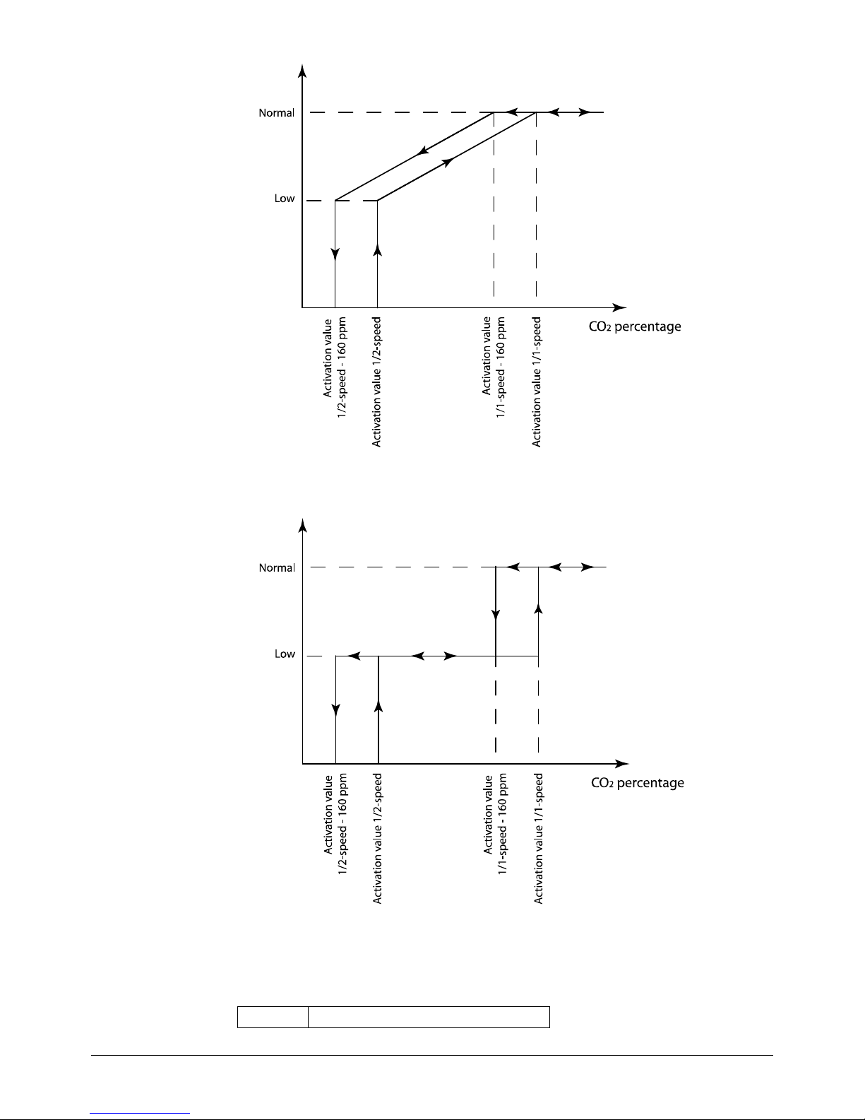
44 Chapter 5 Functional description Manual Corrigo Ventilation, revision R
When used with 2-speed fans they will start using reduced speed when the CO
2
value rises above
control value one and switch to normal speed when the CO
2
value reaches control value two. The
fans will stop when the CO
2
value falls 160 ppm below control value one.
If demand controlled ventilation is activated in co mbination with mixing dampers, and the CO
2
value rises above the setpoint value, the dampers will let in more outdoor air. The function is
controlled by a PI-controller. See section 5.1.3 Heat exchanger types.
The function has a settable minimum running time.
In- and outputs
AI
CO2 sensors

Manual Corrigo Ventilation, revision R Chapter 5 Functional description 45
5.5 Pump control
Digital inputs and outputs can be configured for pump control.
All the pumps can use run indication with malfunc tion alarm or an alar m input co nnected to a motor
protection or similar.
5.5.1 Heating circuit
The circulation pump for the heating circuit will always run when the outdoor temperature is lower
than a settable value (FS +10°C). At higher outdoor temperatures the pump will run when the
heating output is larger than 0V.
If no outdoor temperature sensor has been configured, the stop temperature can be set to 0°C. Then
the pump will only run on heat demand.
The pump has a settable stop delay.
The pump will be exercised once daily at 3 p.m. for one minute or the set shortest running time,
whichever is the longest.
5.5.2 Exchanger circuit, liquid connected exchangers
The circula tion pump for the exchanger cir cuit will run wh en the output to the exchange r valve is
larger than 0V.
The pump has a settable, shortest running time.
The pump will be exercised once daily at 3 p.m. for 1 minute, or the set stop delay, whichever is t he
longest.
5.5.3 Cooling circuit
The circulation pump for the cooling circuit will run when the output to the cooling valve is larger
than 0V.
The pump has a settable, shortest running time.
The pump will be exercised once daily at 3 p.m. for 1 minute, or the set stop delay, whichever is t he
longest.
Corrigo can be configured to block DX cooling if a ”Malfunction P1-Cooling” alarm should occur.
In- and outputs
Heating Exch. Cooling
AI
Outdoor temperature sensor
DO DO DO
Start/stop circulation pump
DI
DI
DI
Run ind/alarm, circ. pump
5.6 Damper control
5.6.1 Close-off dampers
The outdoor air and exhaust air ducts close-off dampers can be controlled by digital outputs or be
hard-wired to the supply air fan relays for normal and reduced speed in such a fashion that the
damper is op en whe n the sup ply air fan is r unnin g. When using p ressure control led fan s the di gital
activation signal is activated as soon as the fan has start conditions. This signal can be used to open
the close-off damper.

46 Chapter 5 Functional description Manual Corrigo Ventilation, revision R
5.6.2 Fire dampers
Fire dampers are normally configured to open on fire alarm. However, they can be configured to be
normally open instead via the display.
Se chapter 16.15 for more information on the function.
Fire damper exercising
Fire damper exercising can be configured. The exercise interval is settable. To be able to use this
function, all the dampers must have end-position switches.
The digital input: "Fire damper e nd-switch monitoring" should be wired to all the fire damper end
position switches.
When the te st cycle is initiated, the outp ut "Fire dampers" will be activated and the dampers will
begin to move. Within the set time (90 sec) the signal on "Fire damper end-switch monitoring" must
change to indicate that the dampers have left their normal positions. If not an alarm will be
triggered.
Then, within the set time, ”Fire damper, end-switch monitoring” mus t change again to indicate that
all the dampers have reached the other end position. If not an alarm will be triggered.
When all dampers have reached the end position the output "Fire dampers" will be reset to drive the
dampers bac k to normal posi tion. Again, within the set t ime (90 sec ) the signal on the i nput "Fire
damper end-switch monitoring"must change to indicate that the dampers have left the end p ositions.
If not an alarm will be triggered.
Then, within the set time, "Fi re damper end-switch monitoring" must change again to indic ate that
all the dampers are back to their normal positions. If not an alarm will be triggered.
The controller can be configured to stop the air handling unit during the damper testing.
All dampers must be wired to the same output in order to get correct results.
The fire alarm input can be configured as normally closed or normally open.
In- and outputs
DO
Outdoor air damper
DO
Exhaust air damper
DO
Fire damper
DI
Fire alarm
DI
Fire damper end switch monitor ing
5.7 Extended running and Exter na l sw it c h
The digital inputs for extende d running ca n be used to force the unit to start alt hou gh t he t i mer sa ys
the running mode should be “Off”. Normal running always takes precedence over reduced speed.
"Extended Operation, Normal" takes precedence over the timer output for reduced speed.
For 2-speed fans and pressure/flow controlled fans there are inputs for normal speed and reduced
speed. The unit will run for the set ti me. If the running t ime is set to 0 the unit will only ru n as long
as the digital input is closed.
The signal ”External switch” will stop the unit, eve n if the timer or one of the signals "Extended
Operation, Normal" or "Extended Operation, Reduced" says it should stay in running mode.
90°
Damper
...
Damper
3
Damper
2
Damper 1
i
E

Manual Corrigo Ventilation, revision R Chapter 5 Functional description 47
In- and outputs
DI
Extended Oper a tion, Normal
DI
Extended Oper a tion, Reduced
DI
External switch
5.8 Time-switch outputs
Up to five digital time-switch outputs can be configured. Each timer channel has a separate
scheduler with two periods per week-day.
Timer output five can be used to control the function Recirculation. See 5.1.11.
In- and outputs
DO
Extra time channel 1
DO
Extra time channel 2
DO
Extra time channel 3
DO
Extra time channel 4
DO
Extra time channel 5
5.9 Alarms
Alarm handling
Alarms are indicated by the red alarm LED on the front or on E3-DSP.
All alarms can be monitored, acknowledged and blocked using the display and buttons or via E3-
DSP.
Alarm priorities
Alarms can be given different priority levels, A-alarm, B-alarm, C-alarm or not active. Digital
outputs can be bound to act as alarm outputs for A-alarms or B/C-alarms or both A- and B/C alarms.
The digital outputs can be inverted, so that an inoperative alarm gives a high output and vice versa.
A- and B-alarms must be ack nowledged to reset. C-alarms automatically reset as soon as there is no
longer a cause for alarm.
Stop function
For each alarm there is the possibility of choosing whether activated alarm should stop control or
not. Automatic restart will take place after removal of the alarm cause and the alarm has been
acknowledged.
For some alarm types such as electric heating high temperature limit and water heating frost
protection it would be dangerous to not stop the unit on ala rm. Therefore, for such alar m types, the
program will always reset the stop function to "Active" even if the operator should choose
"Inactive".
Unfortunately it is not possible to remove the display text concerning the stop function for these
alarm types. This since the available program space demands that all alarms are treated in the same
way in the display.
Note: For alarms that have been set to "Inactive", the extra stop function should also be set to
"Inactive", or unexpected malfunctions may occur.

48 Chapter 5 Functional description Manual Corrigo Ventilation, revision R
Alarm text
The alarm text that should be shown in the display when there is an alarm can be changed using E
tool
©
. For more information, see the E tool© manual.
In- and outputs
DO
Sum alarm A + B
DO
Sum alarm A
DO
Sum alarm B/C

Manual Corrigo Ventilation, revision R Chapter 6 Starting and stopping the unit 49
Chapter 6 Starting and stopping the unit
6.1 Start conditions
The unit will be started and will run when any one of the following conditions is met:
1. Timer output for normal speed or timer output for reduced speed is ON
2. The unit is started manual ly using the Corrigo front panel or via E3-DSP
3. Digital input for extended running is activate d
4. Support control is activated and the present room temperature is higher/lower than the
preset starting value (Support heating/cooling)
5. Demand controlled ventilation is activated and the value at the CO2 sensor is higher tha n
the preset start condition.
6. Recirculation control has been configured and the conditions for recirculation control are
fulfilled.
Possibility to block automatic restart a t p o wer-up
The function ”Automatic restart a t power-up” makes it possible to block automatic restart of the unit
at power-up. At power-up, the B-alarm ”Restart blocked after power on” is generated. Once this
alarm has been acknowledged, the unit will start.
6.2 Stop conditions
The unit will be stopped when any of the following conditions are met:
1. Timer output for normal speed or timer output for reduced speed are OFF, and the signal
for extended running is OFF.
2. Activated frost protection alarm. The unit will restart on resetting of the alar m.
3. Activated fire detector if the function has been configured. The unit will restart on resetting
of the alarm.
4. If the unit has electric he ating and the supply fan fl ow switch al arm or the high temperature
limit alarm is activated.
5. Activation of external switch.
6. The unit is stopped manual ly using the Corrigo front panel or E3-DSP.
7. Support control is activated a nd the present ro om te mpe rat ure is hi gher /lo wer t ha n the pre -
set stop value (support heating/cooling)
8. Demand controlled ventilation is activated and t he value at the CO
2
sensor falls below the
pre-set start condition less the set differential.
9. Recirculation control is active and the conditions for recirculation control are no longer
fulfilled.
10. At an activated alarm configured with the extra function o f stopping the unit on activation.
The unit will restart on resetting of the alarm.

50 Chapter 6 Starting and stopping the unit Manual Corrigo Ventilation, revision R
6.3 Start sequence
Start of the unit will run according to the following sequence:
1. If the contr oll er is co nfi gured fo r water hea ting a nd ha s a n out doo r te mper atur e s ens or and
the outdoor temperature is below +3ºC the heating valve is opened and the heating
circulation pump is started.
2. If the contro ll er is c onfigured wit h a he at e xc ha n ger a nd has a n o utd o or temperature sensor
and the outdoor temperature is below +15ºC the heat exchanger will be run at 100%
capacity for a pre-set time.
3. Signals for outdoor air and exhaust air dampers are activated.
4. The extract air fan or the pressure control of the extract air fan will be started after a preset
time.
5. The supply air fan or the control of the supply air pressure will be started after a preset
time.
6. Thereafter temperature control according to the configured control mode is started. Electric
heating, if configured, is not started until a run signal from the supply air fan or flow
switch has been received. And not yet activated pumps will be started.
7. After a pre-set delay, t he ala rm hand lin g sys tem i s ac ti vate d. The unit i s in no r mal ru nni ng
mode.
6.4 Stop sequence
Stopping of the unit will run according to the following sequence:
1. Deactivation of the alarm handling s ystem.
2. Electric hea ting, if configured, is shut down.
3. After individually set delay times the fans are stopped.
4. Outdoor air and exhaust air dampers are shut down.
5. Actuator signals are set to zero and the pumps are stopped.
6. If shutdown mode is configured, it will be activated.
In order to maintain an acceptable supply air temperature as long as possible, the heat exchanger
will continue t o run during the stop sequence until everything else is stopped.

Manual Corrigo Ventilation, revision R Chapter 7 Display, LEDs and buttons 51
Chapter 7 Display, LEDs and buttons
This section is applicable to Corrigo units with display and buttons but also to the hand terminal E3DSP which can be connected to Corrigo units without display and buttons.
Room units are available with or without display, or as a touch display (see instructions and product
sheets for ED-RU..., ED-RU-D... and ED-TCV).
7.1 Display
The display has four rows of 20 characters and is backlit. The illumination is normally dimmed, but
is activated as soon as a button is pressed. The illumination will be dimmed again after a period of
inactivity.
7.2 LEDs
There are two LEDs on the front: The alarm LED marked with the symbol. The “write enable”
LED marked with the symbol.
The four LEDs placed next to the upper terminal strip will be described later.
7.3 Buttons
There are seven buttons: four arrow buttons which will be called UP, DOWN, RIGHT and LEFT.
The menus in the Corrigo are organized in a horizontal tree structure. The UP /DOWN buttons are
used to move between menus at the present menu level. The RIGHT/LEFT buttons are used to
move between menu levels. When changing parameters the UP/DOWN buttons are used to
increase/decrease the value of the parameter and the RI GHT /LEFT but tons to move bet ween di gits
within the parameter.
• The OK button is used to confirm the choice of a parameter setting. See more in the section
"Change parameters" below.
• The C button is used to abort an initiated parameter change and restore the original value.
• The ALARM button, marked with a red button top, is used to access the alarm list.
7.4 Navigating the menus
The choice of access level/user access determines which menus are shown in the menu system.
The start display, the display nor mally shown, is at the root of the menu tree.

52 Chapter 7 Display, LEDs and buttons Manual Corrigo Ventilation, revision R
Regulator vent. sys
2008-11-20 13:30
System: Running
Sp: 18.0 Act: 18.2°C
Pressing DOWN will move you through the menu cho ic e s at this, the lowest level. UP will move
you back through the choices. Which men us are shown depends on whi ch access level you are using
(see chapter eight for more information about logging on to higher levels).
Using Normal access, the access which normally does not require logging on, only a few basic
menus are shown:
Running mode
Temperature
Air control
Humidity control
Time settings
Access rights
In the menu " R unning mode", you can vie w and set the unit’s running mode, view selected control
functions and view the alarm events.
In the menus "Temperature", "Air control" and "Humidity control", you can view actual values and
setpoint val ues. Setpoints can only be changed if yo u have Operator or Admin access.
In "Time settings", the time, date and set running times are shown. Values can only be changed if
you have Operator or Admin access.
Without logging on to Operator or System level, you are only authorised to change the unit’s
running mode and acknowledge alarms.
With Operator access, you can access more information and change other operation parameters like
setpoints and time functions.
With Admin access, you have full access to the complete menu system and can change all
parameters.
To enter a higher menu level, use UP or DOWN to place the display marker opposite the menu you
wish to access and press RIGHT . At each level there may be several new menus through which you
may move using the UP and DOWN buttons.
Sometimes there are further submenus linked to a menu or menu item. This is indicated by an arrow
symbol at t he rig ht-ha nd ed ge of the display. To choose one, use RIGHT again. To back down to a
lower menu le vel, use LEFT.
Change parameters
In some menus there are parameters that can be set. This is indicated by the yellow LED with
flashing.
A quick blinking (2 times/s) indicates that the parameter can be changed using the present user
access.
A slower blinking (1 time/s) indicates that a higher user access is required to change the parameter.
To change a p arameter, first p ress the OK button. If you need higher authority than you have to
change the parameter, a log on menu will be displayed, see chapter eight below. Otherwise, a cursor
will appear at the first settable value. If you wish to change the value, do so by pressing the UP and
DOWN buttons.
In numbers containing several d igits you can move b etween the digits using the LEFT / RIG HTbuttons.
When the desired value is displayed press OK.
If there are further settable values displayed the cursor will automatically move to the next one.
To pass a value without changing it, press RIGHT.
To abort a change and return to the initial setting, press and hold the C-button until the cursor
disappears.

Manual Corrigo Ventilation, revision R Chapter 8 Access rights 53
Chapter 8 Access rights
There are four different access levels. The Admin level has the highest access, while the Service,
Operator and basic “no-log on” level have the lowest. The choice of access level determines which
menus are shown, as well as which parameters can be changed in the displayed menus.
Admin level gives full read/write access to all settings and parameters in all menus.
Service level gives acces s t o all menus e xcept the submenus "Configuration"/"In- and Outputs" and
"Configuration"/"System".
Operator level gives access to all menus except ”Configuration”.
The basic level only permits changes in "Running mode" and gives read-only access to a limited
number of menus.
Repeatedly press the DOWN button when the start-up display is sho wn until the ar row-marker to
the left of the text-list points to "Access rights ". Press RIGHT.
Log on
Log off
Change password
8.1 Log on
Log on
Enter password:****
Actual level:None
In this menu it is possible to log on to an y access level by entering the appropriate 4-digit code.
The log on menu will also be displayed should you try to gain access to a menu or try to do an
operatio n requiring highe r authority t han you have.
Press the OK button and a cursor marker will app ear at the first digit po sition. Repeated ly press the
UP button until the corr ect digit is displa yed. Press the RIGHT button to move to the ne xt position.
Repeat the procedure until all four digits are displayed. Then press OK to confirm. After a short
while the text on the line: Pre sent level will change to displ ay the ne w log on le vel . P ress the LEFT
button to lea ve the menu.
8.2 Log off
Use this menu to log off from the present level to the basic "no-log on" level.
Log off?
No
Actual level:Admin
Automatic logoff
If the access level is Operator, Service or Admin, the user will automatically be logged off to
Normal after a settable time of inactivity. See also t he section "Auto matic logoff". It is possib le to
remove the automatic logoff, see 8.4 below.

54 Chapter 8 Access rights Manual Corrigo Ventilation, revision R
8.3 Change password
As default Corrigo comes with the following passwords for the different levels:
Admin 1111
Service 2222
Operator 3333
Normal 5555
You can only change the password for log on levels lower or equal to the presently active level, i.e.
if you are logged in as Admin you can change all passwords, but as Operator you can only change
the Operator and Normal passwords. There is no point in changing the Basic password since access
to that level is granted automatically to all users.
Change password for
level:Operator
New password: ****
Note: Do not set the password for Admin to the same value as the password for a lower level since
this will prevent access to the Admin level.
Forgotten your password? If the password for Admin has been changed and then lost, a tempora ry
password can be obtained from Regin. This code is date dependent and only valid for one day.
8.4 Change password to remove automa t ic logoff
If you want to remove the automatic logoff, change the password of the desired level to 0000. After
changing the password, the level will always be activated.
Note: This s hould be done with considerat ion, since no al arm is continuo usly given tha t a certain
level has been activated. However, it is very useful in certain cases, if the unit is intended to be used
by educated personnel or for instance at commissioning.

Manual Corrigo Ventilation, revision R Chapter 9 Running mode 55
Chapter 9 Running mode
Collected here are a number of menus showing running mode, selected functions, alarm events and
status of inp uts and output s .
Running mode
Selected functions
Alarm events
Input/Output
9.1 Running mode, unit
The unit’s ru nning mode can be changed without logging on.
Running mode
Auto
Running time
SAF: 14.6 h
Running time
EAF: 14.6 h
9.2 Selected functions
Shows the present configuration. These are read-only menus. No changes can be made here.
Control function
Supply air control
Fan control
1-speed.
Heating: Water
Exchanger: Plate exc
Cooling: Water
Free cool active: No
Support control
Active: Yes
CO2/VOC active
If time channel on
Fire damper function
Not active
Operation when alarm
Stopped

56 Chapter 9 Running mode Manual Corrigo Ventilation, revision R
Frost protection
Active
Cooling recovery
No
External setpoint
Not active
9.3 Alarm events
Alarm log which conta ins the 40 latest alarm events. The most recent event is listed first. The alarm
log can only be used for viewing the alarm history. Alarms are handled in a special area, see section
18.1.
24 Nov 14:32 B
Malf. SAF
Acknowledged
9.4 Inputs/Outputs
This is a read-only menu blo ck sho wing the present values for all configured inputs and outputs. If
correction factors have been applied to input values, the corrected values will be shown.
This is a read-only menu. No changes can be made here.
AI
DI
UI
AO
DO
Analogue inputs and digital outputs are shown here as examples.
Analogue inputs
AI1: 18.5 Outdoortemp
AI2: 20.3 Supplytemp
AI3: 28.2 Extracttemp
AI4: 19.9 Roomtemp1
Digital outputs
DO1:Off SAF 1/1-speed
DO2:Off EAF 1/1-speed
DO3: On P1-Heating
DO4:Off Sum alarm

Manual Corrigo Ventilation, revision R Chapter 10 Temperature 57
Chapter 10 Temperature
Here you can view all actual and setpoint values for temperature control. The menu is visible to all
users, regardless of log on level. However, to make changes you need at least Operator authority.
The below menus are available, providing the corresponding input has been activated.
Setpoints are available with a separate value for reduced speed. This is achieved using a temperature
offset when the unit runs in reduced speed.
The temperature is available in either Celsius (°C) or Fahrenheit (°F).
Setpoint.
Control mode 1: Supply air control .
Outdoortemp.:18.4°C
Supply air temp
Act.: 19.8°C Setp
Setp.: 20.0°C
Submenu: Setpoint
Supply air temp
Setp.: 20.0°C
Control mode 2: Outdoor compensated supply air control.
Control mode 5: Outdoor temperature dependent supply air or room temperature
control.
Control mode 6: Outdoor temperature dependent supply air or extract air control.
Outdoortemp.:18.4°C
Supply air temp
Act.: 19.8°C Setp
Setp.: 20.0°C
Submenu: " S etpoint curve "
In control modes five and six, the setpoint relationship is used when supply air control is
active.
Use the eight breakpoints to genera te a "setpoint"/"outdoor temperature" relationship.
Both the outdoor and supply air temperatures are changeable for the curve.
Outdoor comp. setp.
-20.0°C = 25.0°C
-15.0°C = 24.0°C
-10.0°C = 23.0°C
Outdoor comp. setp.
-5.0°C = 23.0°C
0.0°C = 22.0°C
5.0°C = 20.0°C

58 Chapter 10 Temperature Manual Corrigo Ventilation, revision R
Outdoor comp. setp.
10.0°C = 18.0°C
15.0°C = 18.0°C
In-between-values are calculated using straight lines between breakpoints. Setpoints for
temperatures lower than the lowest breakpoint and higher than the highest breakpoint are calculated
by extending the line between the two last breakpoints at either end.
Example: At the lower end the setpoint is increasing by 1°C for every 5 °C lowering of the outdoor
temperature. So the setpoint at –23°C would be 25°C + .6x 1.0°C = 25.6°C.
Setpoint. Control mode 3 and 5: Cascaded room temperature control.
Room temp.1
Actual: 22.0°C
Setpoint: 21.5°C
In control mode five, the setpoint is used when cascade connected room control is active.
Submenu for setting the min and max limitation temperatures for the supply air.
If cascade control
max/min supply
setp.
Max: 30.0°C
Min: 12.0°C
If two room sensors have been configure d you will als o get the following menu:
Room temp.2
Actual: 21.8°C
Control mode 4: Cascade connected extract air control.
Control mode 6: Outdoor temperature-dependent supply or extract air control.
Extract air temp.
Actual: 21.0°C
Setpoint: 21.1°C
In control mode six, the setpoint is used when cascade connected extract air control is active.
Submenu for setting the min. and max. limitation temperatu r e s for the supply air.
If cascade control
max/min supply setp.
Max: 30.0°C
Min: 12.0°C
Control mode 7: Outdoor temperature compensated room control.
Room temp1
Actual: 22.0°C
Setp.: 21.5°C
Outdoor comp. setp.
-20.0°C = 25.0°C
-15.0°C = 24.0°C
-10.0°C = 23.0°C

Manual Corrigo Ventilation, revision R Chapter 10 Temperature 59
Outdoor comp. setp.
-5.0°C = 23.0°C
0.0°C = 22.0°C
5.0°C = 20.0°C
Outdoor comp. setp.
10.0°C = 18.0°C
15.0°C = 18.0°C
If cascade control
max/min supply setp.
Max: 30.0°C
Min: 12.0°C
In control mode seven, the room setpoint is compensated based on outdoor temperature. Note that
the curve must be reset for optimum func tionality.
Both the outdoor and room temperature are changeable for the curve.
Control mode 8: Outdoor temperature compensated extract air control.
Extract air temp
Actual: 21.0°C
Setp.: 21.1°C
Outdoor comp. setp.
-20.0°C = 25.0°C
-15.0°C = 24.0°C
-10.0°C = 23.0°C
Outdoor comp. setp.
-5.0°C = 23.0°C
0.0°C = 22.0°C
5.0°C = 20.0°C
Outdoor comp. setp.
10.0°C = 18.0°C
15.0°C = 18.0°C
If cascade control
max/min supply setp.
Max: 30.0°C
Min: 12.0°C
In control mode 8, the extract air setpoint is compensated based on outdoor temperature. Note that
the curve must be adjusted for optimal functionality.
Both the outdoor and extract air temperature are changeable for the curve.
Support control heating
Support heating
Room temp for
Start: 15.0°C
Stop: 21.0°C

60 Chapter 10 Temperature Manual Corrigo Ventilation, revision R
Support control cooling
Support cooling
Room temp for
Start: 30.0°C
Stop: 28.0°C
Frost protection temperature
Frost protection
Actual: 30.9°C
De-icing exchanger
De-icing exchanger
Actual: 11.2°C
Setpoint: -3.0°C
Hysteresis: 1.0°C
Heat exchanger efficiency monitoring
Efficiency exch.
Actual: 93%
Output exchanger
Actual: 100%
Recirculation (see 5.1.11)
Temp.setpoint when
recirc. (Supply/
Extract/Room)
18.0°C
Offset SAF when
frequency control
and recirculation:
0.0 Pa
"Offset SAF" makes it possible to add an offset to the setpoint during normal operation. If pressure
control has been configured, the offset is set in Pa. If flow control has been configured, it is set in
m
3
/h. If manual control has been configured, the offset is set in percent.
Extra control circuit (see 5.2)
Extra control circuit
Actual: 21.2°C
Setpoint: 20.0°C
Enthalpy control
Enthalpy indoor:
33.8 KJ/Kg
Enthalpy outdoor:
35.0 KJ/Kg

Manual Corrigo Ventilation, revision R Chapter 10 Temperature 61
Submenus
Outdoortemp
Act.: 12.8 °C
Humidity Outdoor
Act.: 98.7% RH
Indoortemp
Act.: 17.2 °C
Humidity indoor
Act.: 55.7 % RH
Status enthalpy control
Override cool Recovery
due to Enthalpy:
Active

62 Chapter 11 Air control Manual Corrigo Ventilation, revision R
Chapter 11 Air control
Pressure control SAF and EAF
When using pressure or flow controlled fans, the setpoint can be temperature compensated.
The compensation has the default value 0 Pa, i.e. no compensation is added. The compensation is
linear between the setting points. The compensation can be positive or negative.
The same compensation normally applies to both fans. Using E tool
©
, you can choose to
compensate only the supply air fan.
The same compensation is applied to both "Normal" and "Reduced", which means that you need to
take caution when using this fu nction so the press ure does not beco me too low or even nega tive
when running reduced speed.
Depending on the choice of fan control, different combinations of the menus below will be shown.
Pressure control SAF (there are corresp o n d ing menus for EAF)
Pressure contr. SAF
Actual: 480 Pa
Setp.: 490 Pa
Submenu "Setpoint"
Pressure contr. SAF
Setp 1/1: 490 Pa
Setp 1/2: 300 Pa
Submenu "Outdoor compensation"
Outd. comp. setp.
-20 °C = -50 Pa
10 °C = 0 Pa
Act. Comp: -5 Pa
Submenu "Extra compensation curve"
Comp.sens.:Roomtemp1
15 °C = 0 Pa
20 °C = 0 Pa
25 °C = 0 Pa
Submenu “Controller output compensation if cooling”
Controller output
comp if cooling
0 at HCOUT= 0%
100 at HCOUT= 0%
Submenu “Controller output compensation if heati ng”
Controller output
comp if heating
0 at HCOUT= 0%
100 at HCOUT= 0%
The compensation follows the c urrent control quantity, in this case pre ss ure.
Submenu “Controller output compensation”
Controller output
compensation
Not active

Manual Corrigo Ventilation, revision R Chapter 11 Air control 63
Submenu “Compensation only when”
Compensation only
when:
1/1-speed: No
defrosting: No
Flow units can be measured in both m3/h (cubic meters per hour) and in CFM (cubic feet per
minute).
Flow control SAF (there are correspondi n g m enus for EAF)
Flow control SAF
Actual: 1800 m3/h
Setp.: 2000 m3/h
Submenu "Setpoint"
Flow control SAF
Setp 1/1: 2000 m3/h
Setp 1/2: 1000 m3/h
Submenu "Outdoor compensation"
Outdoor comp. setp.
-20 °C = 0.0 m3/h
10 °C = 0.0 m3/h
Act. Comp: 0.0 m3/h
Submenu "Extra compensation curve"
Comp.sens.:Roomtemp1
15 °C = 0 m3/h
20 °C = 0 m3/h
25 °C = 0 m3/h
Submenu “Cont ro ller output compensation if cooling”
Controller output
comp if cooling
0 at HCOUT= 0%
100 at HCOUT= 0%
Submenu “Controller output compensation if heati ng”
Controller output
comp if heating
0 at HCOUT= 0%
100 at HCOUT= 0%
The compensation follows the current control q uantity, in this case pressur e.
Submenu “Controller output compensation”
Controller output
compensation
Not active
Submenu “Compensation only when”
Compensation only
when:
1/1-speed: No
defrosting: No

64 Chapter 11 Air control Manual Corrigo Ventilation, revision R
Flow units can be measured in both m3/h (cubic meters per hour) and in CFM (cubic feet per
minute).
Manual frequency control SAF (there are c orresponding menus for EAF)
Frequency control
manual SAF
Output: 75%
Submenu "Setpoint"
Frequency control
manual SAF
Output 1/1: 75%
Output 1/2: 50%
Submenu "Outdoor compensation"
Outdoor comp. outp.
-20 °C = 0 %
10 °C = 0 %
Act. Comp: 0 %
Submenu "Extra compensation curve"
Comp.sens.:Roomtemp1
15 °C = 0 %
20 °C = 0 %
25 °C = 0 %
Submenu “Controller output compensation if cooling”
Controller output
comp if cooling
0 at HCOUT= 0%
100 at HCOUT= 0%
Submenu “Controller output compensation if heati ng”
Controller output
comp if heating
0 at HCOUT= 0%
100 at HCOUT= 0%
The compensation follows the curr ent control quantity, in this case %. T he function
should not be used when fa n setpo int is set to %, as t he fans will then ris k stopp ing in
some mo des.
Submenu “Controller output compensation”
Controller output
compensation
Not active
Submenu “Compensation only when”
Compensation only
when:
1/1-speed: No
defrosting: No
Flow units can be measured in both m3/h (cubic meters per hour) and in CFM (cubic feet per
minute).
CO2
CO2
Actual:920ppm
Setp:850pm

Manual Corrigo Ventilation, revision R Chapter 12 Humidity control 65
Chapter 12 Humidity control
Humidity control can be configured as Humidification, Dehumidificatio n or both Humidification
and Dehumidification.
Two humidity sensors can be connected, a room sensor for control and an optional duct sensor for
maximum limiting. The limit sensor can be omitted.
The humidity control is handled by a PI-controller.
The humidity sensors must give 0…10 V DC for 0…100 % RH.
Humidity sensor room
Humidity room
Actual: 51.9% RH
Setp: 50.0% RH
Humidity sensor duct
Humidity duct
Actual: 72.2% RH
Max limit: 80.0% RH
Hyst.: 20.0% RH
If the maximum limitation is 80 % RH and the hysteresis i s 20 % RH, the controller output signal
will begin decreasing at 60 % RH. When halfway to 80 % RH (i.e. when at 70 % RH), half the
output signa l will be da mped. If the humidity i n the duct st ill reaches 8 0 % RH, the entire outp ut
signal will be damped.

66 Chapter 13 Time settings Manual Corrigo Ventilation, revision R
Chapter 13 Time settings
General
Corrigo has a year-base clock function. This means that a week-schedule with holiday periods for a
full year can be set. The clock has an automatic summertime/wintertime change-over.
Individual sc hed ules for each week -day plus a separate holiday setting. Up to 24 individual holiday
periods can be configured. A holiday period can be anything from one day up to 365 days. Holiday
schedules take precedence over other schedules.
Each day has up to two individual running periods. For two-speed fans and pressure controlled fans
there are daily individual schedules for normal speed and reduced speed, each with up to two
running peri ods.
Up to 5 digital outputs can be used as timer controlled outputs. Each with individual weekschedules with two activation periods per day. These outputs can be used to control lighting,
doorlocks etc.
Time/Date
Timer Normal speed
Timer Reduced speed
Extended running
Timer output 1
Timer output 2
Timer output 3
Timer output 4
Timer output 5
Holidays
13.1 Time / Date
This menu shows and permits the settin g o f ti me and date.
Time is shown in 24-hour for mat .
Date is shown in the format YY:MM:DD.
Time: 18:21
Date: 04-08-04
Weekday: Wednesday
13.2 Timer Normal speed
There are eight separate setting menus, one for each weekday and one extra for holidays.
Holiday schedules take precedence over other schedules.
For 24 hour running, set a period to 0:00 – 24:00.
To inactivate a period, set the ti me to 00:00 – 00:00. If both periods of a day are set to 0:00 – 0:00,
the unit will not run at 1/1-speed that day.
Normal speed
Monday
Per 1: 07:00 – 16:00
Per.2: 00:00 - 00:00

Manual Corrigo Ventilation, revision R Chapter 13 Time settings 67
If you want to r un the unit from o ne da y to another, e.g. from Mon 22:00 to Tue 09:00, the desired
running time for both days must be entered.
Normal speed
Monday
Per 1: 07:00 – 16:00
Per.2: 22:00 - 24:00
Normal speed
Tuesday
Per 1: 00:00 – 09:00
Per.2: 00:00 - 00:00
13.3 Timer Reduced speed
These settings will be ignored if single speed fans are configured.
Should periods for normal speed and periods for reduced speed overlap, normal speed takes
precedence.
There are eight separate setting menus, one for each weekday and one extra for holidays. Holiday
schedules take precedence over other schedules. For 24 hour running, set a period to 00:00 – 24:00.
To disable a period, set it to 00:00 – 00:00. If both periods of a day are set to 00:00 – 00:00, t he uni t
will not run at "Reduced speed" that day.
Reduced speed
Sunday
Per 1: 10:00 – 16:00
Per.2: 00:00 - 00:00
13.4 Extended running
Digital inputs can be used to fo rce the unit to s tart altho ugh the timer sa ys the r unni ng mode should
be “Off”.
For 2-speed fans and pressure/flow controlled fans, inputs for normal speed and reduced speed can
normally be us ed.
The unit will run for the set time. If the running time is set to ze ro the unit will only run as long as
the digital input is closed.
Extended running
60 min
Time in ext. Running
0 min
13.5 Timer outputs 1…5
Up to 5 digital outputs can be used as timer controlled outputs. Each with individual weekschedules with two activation periods per day. Each output has eight separate setting menus, one for
each weekday and one extra for holidays. Holiday schedules take precedence over other schedules.
Only the time channels which have been configured, i.e. have been wired to a digital output, will be
shown.
Timer output 2
Wednesday
Per.1: 05:30 – 08:00
Per.2: 17:00 – 23:00
If the function "Recirculation" has been configured (see 5.1.11), "Timer output 5" can be used to
control start/stop of the recirculation function.

68 Chapter 13 Time settings Manual Corrigo Ventilation, revision R
13.6 Holidays
Up to 24 separate holiday periods for a full year can be set.
A holiday period can be any number of consecutive days from 1…365. The dates are in the format:
MM:DD.
When the present date falls within a holiday period, the scheduler will use the settings for the
weekday “Holiday”.
Holidays (mm:dd)
1: 01-01 – 02-01
2: 09-04 – 12-04
3: 01-05 – 01-05

Manual Corrigo Ventilation, revision R Chapter 14 Manual / Auto 69
Chapter 14 Manual / Auto
General
In this menu the running mode of all the configured output signals and a number of control
functions can b e manua ll y control led. T his is a ve ry hand y feat ure whic h simpl ifie s the c heckin g of
individual functions in the Corrigo.
The running mode for the whole unit is set in the menu "Running mode". See section 9.1.
The suppl y air c ontr oll er 's out put sig nal c an b e manua lly set (Ma nua l/A uto) to a ny va lue b etwee n 0
and 100 %. The temperat ur e o ut put signals will change acc or d ingl y i f t hey are in " Auto " mod e . I t is
also possible to manually control e a c h o f the temperature output signals individually.
All the configured digital outputs can be set to "Auto", "Off" or "On".
Since leaving any of the outputs in manual co ntrol will disrupt the nor mal control, an ala rm will be
generated as soon as any output is set to a manual mode.
Since the me nu s vary accordi ng t o the c o nfi gur a tio n o f t he o utp uts o nl y t he mos t common ones will
be shown here . Fo r t he d i git al s ig nal s yo u c an no r mall y choose bet wee n " A uto " a nd "On" and "Off"
or similar words indicating the two possible manual states of the digital output.
Manual/Auto
Supply air controller running mode
Can be set to "Auto", "On" or "Off". In manual "On" mode the output signal can be set 0…100 %.
The outputs "Y1", "Y2" a nd "Y3", if in "Auto" mode, will follow the signal according to the set
split values.
Supply temp contr.
Auto
Manual set: 42.0
Start signal "SAF" and "EAF"
Can be set to manual 1/1-speed, manual 1/2-speed and off. Manual 1/2-speed is not valid for single
speed fans.
SAF
Auto
EAF
Auto
With pressure controlled fa ns you get the follo wing menu: Can b e set to " Auto", " Manual normal" ,
"Manual reduced", "Manual" and "Off". In "Manual" mode the output signal can be set 0…10 V.
Pressure SAF: Auto
Manual set: 0.0

70 Chapter 14 Manual / Auto Manual Corrigo Ventilation, revision R
EAF: Auto
Manual set: 0.0
Y1 heating out put
Heating
Auto
Manual set: 0.0
Y2 heat exchanger
Exchanger
Auto
Manual set: 0.0
Y3 cooling
Cooling
Auto
Manual set: 0.0
Humidification/dehumidification
Humidification/Dehumidi
fication
Auto
Manual set: 0%
Circulation pumps: Heating, Exchanger and Cooling
P1-Heating
Auto
P1-Exchanger
Auto
P1-Cooling
Auto
Dampers: Outdoor air, Recirculation air, E xhaust air and Fire dampers
Outdoor air damper
Auto
Exhaust air damper
Auto
Extra control circuit
Extra ctrl. unit
Auto
Manual set: 0.0

Manual Corrigo Ventilation, revision R Chapter 14 Manual / Auto 71
Extra seque nce Y4
Extra sequence Y4
Auto
Manual set: 0.0
Extra sequence Y5
Extra sequence Y5
Auto
Manual set: 0.0

72 Chapter 15 Settings Manual Corrigo Ventilation, revision R
Chapter 15 Settings
In this menu group all settings for all activated functions should be available. The menu group is
only available when logging on as Admin. Depending on what choices have been made during
configuration, some of the alternatives in this menu group ma y not be shown.
Settings
Control temp
Control pressure
Control flow
Control humidity
Control CO2
Control extra unit
Alarm settings
15.1 Control temp
Supply air controller
Supply air control
P-band: 33.0 °C
I-time: 100.0 sec
The set P-band for the supply air c ontrolle r is for the whole co ntroller signal. T his means that t he P band for each sequence is proportionate to the split percentage values given to sequences.
For example:
P-band for the supply air controller is set to 25 K. The split is set so that cooling ge ts 0 …2 0 % = 20
%, the exchanger gets 30…50 % = 20 % and the heater gets 50…100 % = 50 %.
The individual P-bands will then be:
Chiller: 20 % of 25°C = 5°C
Exchanger: 20 % of 25°C = 5°C
Heating: 50 % of 25°C = 12.5°C
The remaining 2.5°C are the neutral zone between cooling and exchanger.
The split values are set in t he configura tion submenu O th er p ara me ters.
If cascade control
max/min supply setp.
Max: 30°C
Min: 12°C
Room controller
Room control
P-band: 100.0 °C
I-time: 300.0 sec
Extract air controller
Extract air control
P-band: 100.0 °C
I-time: 300.0 sec

Manual Corrigo Ventilation, revision R Chapter 15 Settings 73
Shutdown mode
Shutdown mode
P-band: 100.0 °C
I-time: 100 sec
Frost protection temperature
Frost protection
temperature
Frost protection
Active
Setp shutdown: 25°C
P-band active: 5°C
Fast stop at
frost-protection alarm
Yes
"Setp shutdown" is the shutdown mode setpoint.
P-band active 5°C means that the frost pr otection controller will start overriding the heating output
when the frost protection temperature is less than five degrees above the set frost alarm limit. The
default alarm limit is 7°C. It can be changed in the menu Settings/Alarm settings/Alarm
limits/Alarm limit frost protection.
Exchanger de-icing
De-iceing
P-band: 100 °C
I-time: 100 sec
15.2 Control pressure
Pressure control SAF
Pressure control SAF
P-band: 500 Pa
I-time: 60 sec
Min Output: 0 %
Pressure control EAF
Pressure control EAF
P-band: 500 Pa
I-time: 60 sec
Min Output: 0 %
15.3 Control flow
Flow control SAF
Flow control SAF
P-band: 1000 m3/h
I-time: 60 sec
Min Output: 0 %

74 Chapter 15 Settings Manual Corrigo Ventilation, revision R
Flow control EAF
Flow control EAF
P-band: 1000 m3/h
I-time: 60 sec
Min Output: 0 %
15.4 Humidity control
Control humidity
P-band: 100.0 %RH
I-time: 300.0 sec
15.5 Control Extra unit
Control extra
unit
P-band: 33.0 °C
I-time: 100.0 sec
15.6 Alarm settings
Alarm settings
Alarm limits
Alarm delays
Restore alarm
15.6.1 Alarm limits
Alarm limits, supply air
Al. lim. supply air
Control dev: 10.0 °C
High temp: 30.0 °C
Low temp: 10.0
Alarm limits, extract air
Al. lim. extract air
High temp: 30.0 °C
Low temp: 10.0 °C
Alarm limits, room
Al. lim. room air
High temp: 30.0 °C
Low temp: 10.0 °C
Alarm limit frost protection
Alarm limit frost
protection
7.0 °C

Manual Corrigo Ventilation, revision R Chapter 15 Settings 75
Alarm limit, pressure
Control dev SAF
40.0 Pa
Control dev EAF
40.0 Pa
Alarm limit Humidity
Control deviation
humidity
10 %
Alarm limit, exchanger efficiency
Low efficiency
50.0 %
Service alarm filter
Service alarm
(Filter alarm)
Time until alarm
Activates: 0 month
15.6.2 Alarm delays
Alarm delay, supply air
Al. del. supply air
Control dev: 30 min
High temp: 5 sec
Low temp: 5 sec
Alarm delay, extract air
Al. del. extract air
High temp: 30.0 min
Low temp: 30.0 min
Alarm delay, room
Al. del. room air
High temp: 30.0 min
Low temp: 30.0 min
Alarm delay, frost protection
Alarm delay
Frost prot.: 0 sec
Frost risk: 0 sec
Alarm delay control SAF and EAF
Alarm delay control
dev. pressure
SAF: 30 min
EAF: 30 min
Alarm delay, Humidity
Alarm delay control
deviation humidity 30
Min

76 Chapter 15 Settings Manual Corrigo Ventilatio n, revision R
Alarm delay, exchanger efficiency
Low efficiency
30 min
Alarm delay, fan malfunction
Alarm delay malfunc.
SAF: 120 sec
EAF: 120 sec
Alarm delay, pump malfunction
Alarm delay malfunc.
P1-Heating: 5 sec
P1-Cooling: 5 sec
P1-Exchan.: 20 sec
Alarm delay, misc.
Alarm delay
Filter mon.: 180 sec
Flow switch: 5 sec
Frost prot.: 0 sec
Ext. Frost prot. DI refers to the digital inp ut si gnal Deicing Heat exchanger.
Alarm delay, misc. 2
Alarm delay
Deicing DI: 0 sec
Fire alarm: 0 sec
Ext. alarm: 0 sec
Frost protection DI refers to the d igital input signal De-icing thermostat exchanger.
Alarm delay, misc. 3
Alarm delay
Elec. heat: 0 sec
Sensor error: 5 sec
Rot.sent.exch: 20 sec
15.6.3 Restore alarm
Service alarm
(filter alarm)
Time counter set to
zero: No
15.7 Save and restore settings
Restore factory
settings: No
Restore user settings:
No
In this menu, it is possible to r estore all parameters to their factor y settings or to the user settings
they were saved as earlier, see below.
Save user settings: No
The present configuration can be saved in a separate memory area and can later be restored using
the previous menu, "Restore user set t ings".

Manual Corrigo Ventilation, revision R Chapter 16 Expansion model 77
Chapter 16 Expansion model
2 and 3 port Corrigo units are available with or without display. Both models have a TCP/IP port
and one or two serial ports. For a list of the various models, see the Corrigo model overvie w in
chapter 2.
16.1 Ports
The ports are used for connecting to E tool© and, possibly, a SCADA system. In an E…3W-3
model, port 3 is the TCP/IP output.
The serial ports (ports 1 and 2) are used for expansion purposes, e.g for connection of expansion
units, external display and Vacon NXL/Lenze SMV/Omron/Emerson/LS/EBM/Danfoss FC 101
frequency converters. A maximum of two frequency converters and two expansion units can be
connected. T he units must be Co rr igo co ntroller s. There is no point in using slave co ntroller s with a
display, si nce the d isplay c annot b e used or show an ything. Howeve r, an E3 -DSP is required when
initially starting up slave units without disp lay. All configuration takes place using E too l
©
, or via
the display on the master contro ller. All inputs and outputs can be viewed in the master controlle r.
For configura tion, see chapter 17.
As of version 3.1, frequency converters and expansion units can be used toget her.
Ports 1 and 2 have the same functions. They can, ho wever, not be configured to have the same
function at the same time. The TCP/IP port (port 3) can be used to connect the controller to
CLOUDigo or, optionally, to load a web page to the unit. For more information, see the E tool
©
manual.
16.2 Wiring
16.2.1 Vacon/Lenze/Omron/Emerson/LS/EBM frequency
converters
If the Corrigo is intended to control of one or two of the Vacon NXL/Lenze SMV/Omron
V1000/Emerson frequency converters, Modbus communication via port two is utilised.
For additional settings for frequency converters, see appendix at the end of this document.

78 Chapter 16 Expansion model Manual Corrigo Ventilation, revision R
16.2.2 Expansion units EXOline
Communication between the master and expansion units takes place via EXOline. The slave
controllers will be given the addresses 241:1 and 241:2 (ELA:PLA) respectively.
16.2.3 Expansion units LON
For a 2 or 3 port Corrigo master to be able to communicate via LON, the first expa nsion unit must
have a LON port. Communication between the master and expansion units takes place via EXOline.

Manual Corrigo Ventilation, revision R Chapter 17 Configuration 79
Chapter 17 Configuration
Start by log ging on as Admin. See chapter 8.
Move the marke r using the DOWN and UP buttons until it is opposite the menu ”Configuration”
and press RIGHT.
The configur ation main menu is sho wn (different men us are visible depend ing on the configur ed
inputs and out puts).
Inputs/Outputs
Sensor settings
Control function
Fan control
Extra control unit
Extra sequence Y4
Extra sequence Y5
Heating
Exchanger
Cooling
Pump control
Free cooling
Support control
CO2/VOC control
Fire function
Humidity control
Exchanger de-icing
Cooling recovery
Enthalpy control
Min lim. dampers
External setpoint
Run ind/Motor prot.
Actuator type
Actuator run time
Actuat. period time
Step controllers
Recirculation
Pretreatment
Alarm settings
Communication
Other parameters
System
17.1 Inputs and outputs
AI
DI
UI
AO
DO
General
Free configuration
Any control signal can be bound to any in- and output , t he o nly r estr icti on b ei ng t hat d igi ta l sig nals
cannot be bound to analogue inputs and vice versa. It is up to the user doing the binding to make
sure that activated functions are bound to appropriate in- and outputs.
Delivery setting
On delivery, all physical in- and outputs have already been bound to a signal.
The delivery settings are suggestions only and can easily be changed.

80 Chapter 17 Configuration Manual Corrigo Ventilation, revision R
17.1.1 Analogue inputs AI
AI1
Sign: Outdoor temp
Raw value: 18.4
Compensation:0.0
All analogue inputs are for PT1000 or 0…10 V.
Input signals can be compensated e.g. for wiring resistance.
The raw value will show the actual, uncompensated input value.
If inputs have been assigned to pressure or flow control of fans, alternatively humidity or CO
2
control, the following menus will appear:
SAF Pressure at
0V: 0.0 Pa
10V:500.0 Pa
Filter factor: 0.2
CO2 at
0V: 0.0 ppm
10V: 2000 ppm
Filter factor: 0.2
Set the parameter values that should correspond to the input signal levels 0 V and 10 V.
The filter fac tor is t he da mping you want the p rogr am to work with i n ord er to r educe the i nflue nce
of potential signal fluctuations on the sensor inp ut. The filter factor can be changed via the displa y
or E tool
©
and is found after ”analogue inputs” in ”configuration”. A new value is calculated using
the following formula:
New value = old value * filter factor + raw value * (1 - filter factor)
17.1.2 Digital inputs DI
DI1
NO/NC: NO Signal:
Filter alarm 1
Status: No
To simplify adaptation to external functions, all digital inputs can be configured to be either
normally open, NO, or normally closed, NC.
The inputs are as standard normally open, i. e. if the input is closed, the function connected to the
input in Corrigo is activated.
Be careful when changin g the i nput fr om NO t o NC si nce so me digit al f unctio ns can b e co nfigur ed
to either NO o r NC themselves. For e xample, you can choose if the Fire a larm input should be
activated when it is closed or opened. Therefore, there is a risk that the signal is changed twice and
the result is the opposite of the desired.
17.1.3 Universal inputs UI
On the largest hardware version, E28 there are universal inputs. These can individually be
configured as either analo gue input s or as digital inputs. Whe n configure d as analogue inputs the y
can be bound to any of the analogue signals described under Analogue signals.
When configured as digital inputs they can be bound to any of the digital signals described under
"Digital signals".
UI1
Choose AI or DI sign
AI sign: SAF pressure
DI sign: Not used

Manual Corrigo Ventilation, revision R Chapter 17 Configuration 81
After choosi ng AI o r DI signa l (t he unuse d alternative must be set to not activ e) there are submenus
with settings. These menus are accessed by pressing RIGHT.
UAI1
Sign: SAF pressure
Raw Value:8.5
Compensation: 0.0
UDI1
NO/NC: NO Signal
Not used
Status: No
To simplify adaptation to exte rnal functions, all universal inputs configured as digital inputs can be
set to be either normally open, NO, or normally closed, NC.
The inputs are as standard normally open, i. e. if the input is closed, the function connected to the
input in Corr igo is activated.
Be careful wh en cha ngin g the inp ut fro m NO to NC sinc e so me digita l func tions can b e co nfigur ed
to either NO o r NC themselves. For e xample, you can choose if the Fire a larm input should be
activated when it is closed or opened. Therefore, there is a risk that the signal is changed t wice and
the result is the opposite of the desired.
17.1.4 Analogue outputs
Analogue outputs are 0…10 V DC.
AO1
Sign: Y1-Heating
Auto
Value: 0.0 V
Analogue outputs can be set in run mode "Auto", "Manual" or "Off".
17.1.5 Digital outputs
DO1
Signal: SAF 1/1-speed
Auto
Status: On
Digital outputs can be set in run mode "Auto", "Manual-On" or "Manual-Off".
17.2 Sensor settings
PT1000 setpoint devices can be connected to function as outdoor and room temperature sensors.
Alternatively, 0...10 V transmitters can also be used.
Room temp1
Sensor type: PT1000
If any of the sensors are set to 0...10 V, the sensor can be scaled using the right arrow key on the
controller:
Room temp1
0V = 0°C
10V = 100°C

82 Chapter 17 Configuration Manual Corrigo Ventilation, revision R
17.3 Control function
Control function
Mode:
Supply air control
There are eight different control functions to choose from:
1. Supply air control.
2. Outdoor-temperature compensated supply air control.
3. Cascaded room temperature control
4. Cascade connected extract air temperature control.
5. Outdoor temperature dependent switching between outdoor compensated supply air
temperature control and room temperature control
6. Outdoor-temperature controlled switching between Outdoor-temperature compensated
supply air control and Cascade connected extract air temperature control.
7. Outdoor compensated room temperature control
8. Outdoor compensated extract air control
For detailed description of the control modes, see section 5.1.1 Control modes.
In control modes five and six, there is a submenu for setting of the change-over outdoor
temperature.
Outdoor temp for
control mode change
13°C
17.4 Fan control
Fan control
1-speed
Choose between "Single-speed", "Two-speed", "Pressure control", "Flow control", "Frequency
manual" (fi xed output), "Fr equency external co ntrol", "SAF wit h EAF slave", o r "SAF with EAF
flow control".
For detailed description of fan control alternatives, see section 5.4 Fan control.
Flow control
If flow control has been configured, there is a submenu for setting of calculation parameters for
conversion of pressure to flow. There are two menus, one for "SAF" and one for "EAF".
SAF flow control
factors
K-constant: 100
X-constant: 0.50
For more detailed description, see the section Air flow control under 5.4.1 Pressure control.

Manual Corrigo Ventilation, revision R Chapter 17 Configuration 83
SAF with EAF slave / EAF with SAF slave
If fan slave operation has been configured, there is a submenu for setting the CAV factor, a factor
which determines the slave fan output in relation to the output of the c ontrolling fan.
SAF/EAF CAV factor:
1.00
For more detailed description, see the section SAF with EAF slave under 5.4.1 Pressure control.
SAF with EAF flow control / EAF with SAF flow control
If fan slave operation and flo w control ha s been configured, there are submenus for setting the flow
calculation factors for "SAF" and "EAF", and the CAV factor for "SAF/EAF".
SAF flow control
factors
K-constant: 100
X-constant: 0.50
EAF flow control
factors
K-constant: 100
X-constant: 0.50
SAF/EAF CAV factor:
1.00
For more detailed description, see the section SAF with EAF flow control / E AF with SAF flo w
control under 5.4.1 Pressure control.
Crosswise interlock between fans
Crosswise interlock means that if one of the fans stops running, the other fan will automatically stop
as well.
Crosswise interlock
between SAF and EAF
No
17.5 Extra control circuit
The extra control circuit can be configured to be either constantly active or to be active only when
the regular control circuit is active.
Mode extra unit
Running if
unit runs
The extra control circuit can be configured to be either a heating or a cooling circuit.
Control mode extra
unit:
Heating

84 Chapter 17 Configuration Manual Corrigo Ventilation, revision R
17.6 Extra sequence Y4
"Extra sequence Y4" can be configured to one of the following alternatives: " Active", "Active with
cooling recovery", "Active with enthalpy control" and "Active with both cooling recovery and
enthalpy control".
Mode Extra Sequence Y4
Not active
17.7 Extra sequence Y5
"Extra sequence Y5" can be configured to “Active” or “Not active”.
Mode Extra Sequence Y5
Not active
17.8 Heating coil
Heating
water
The heater can be set to "Water", "Electric", "Water/Electric" or "Not used".
For detailed description of heater alternatives, see section 5.1.2 Heater types.
17.9 Exchanger
Exchanger
Rot. Exch
The heat exchanger unit can be set to one of the following alternatives:
• Plate exchanger
• Rotating exchanger
• Liquid connected exchanger
• Mixing dampers
• Not connected
• Damper limiting for minimum outdoor air percentage is settable 0…100%.
In the submenu parameters for outdoor temperature control of exchanger can be set.
Outd. temp control of
exch: Off
Outd. temp start: 10°C
Diff. stop: 0.2°C
For detailed description of exchanger alternatives, see section 5.1.3 Heat exchanger.

Manual Corrigo Ventilation, revision R Chapter 17 Configuration 85
17.10 Chiller
Cooling
Water
Select chiller type: "Water", "DX", " DX with exchanger control" or "Not used".
For detailed description of DX-cooling, se section 5.1.4 Step controllers.
If DX cooling has been configured, there are submenus for setting of certain operation parameters.
Min limit lowering
If DX cooling is used in combination with room or extract air control, the suppl y air temperature
minimum li mit value can be l owered to give s moother (more co ntinuous) running of the chillers.
The set lowering of the limit value is activated when the DX cooling is running.
Lowering of min
limit for supply air
control on active
DX cooling: 5.0°C
This parameter is also used for setting the lowering of the cooling setpoint when running "DX
cooling with exchanger control".
See 5.1.4.
Blocking the DX cooling at low out door te m p
Outdoor temperature dependent blocking of DX cooling is individually settable for each cooling
step. If the outdoor temperat ure is belo w the set value, it is not possible to activate the co oling step.
The function has a 1K hysteresis, i.e. if a cooling step is blocked, it can only be activated again
when the outdoor temperature has risen to 1K above the set value.
Block DX-cooling,
step1, at outdoor temp.
lower than 13.0 °C
Blocking of DX cooling on cooling pump alarm
DX cooling can be blocked on activation of the cooling pump alarm.
Block DX-cooling on
alarm
”Run error P1cooler”:No
Override of reduced speed for DX cooling
Override to normal quantity of air for DX cooling whe n the unit runs on reduced quantity of air. The
fans can be set to normal operation when cooling is required at high outdoor temperatures (e.g.
>14°C, the same temperature li mit as for blocking of DX cooling).
Force normal
speed if active
DX-cooling:Yes

86 Chapter 17 Configuration Manual Corrigo Ventilation, revision R
17.11 Pump control
P1-Heating
P1-Exchanger
P1-Cooling
In these menus the parameters for pump control are set.
If, for any of the control circuits, no output is configured for pump control these settings will be
ignored.
P1 Heating
Pump stop: Yes
Stop delay: 5 min
Outd. Temp stop: 10°C
Differential: 1.0°C
P1 Exchanger
P1-Exchanger
Stop delay: 5 min
P1 Cooling
P1-Cooling
Stop delay: 5 min
For a detailed description of pump functions, see the section Pump control.
17.12 Free cooling
Free cool active:Yes
Outd. temp activation
22.0°C
Outd. Temp night
High: 18.0°C
Low: 10.0°C
Room temp min 18.0°C
Hour for start/stop
Free cooling
Start: 0
Stop: 7
Time to block heat
output after
free cooling
60 min
Fan output
when free cooling
SAF: 0 %
EAF: 0 %

Manual Corrigo Ventilation, revision R Chapter 17 Configuration 87
Outdoor sensor
placed in intake
channel
No
For detailed description, see section 5.1.6 Free cooling.
17.13 Support control
Note: If you select the function support control without EAF (e xtra c t a ir fan), a recirculation damper
must be used. See more in section 5.1.5.
Support control
Active: Yes
EAF running during
support contr: Yes
Minimum running time
Min. run time for
support ctrl: 20 min
For detailed description, see 5.1.5 Support control.
17.14 CO2 Demand control
CO2/VOC active
Never
Type: Mixing dampers
Min. time: 20 min
Activation level
1/2-speed: 800 ppm
1/1-speed: 1000 ppm
diff: 160 ppm
For detailed description, see the section Demand control.
17.15 Fire function
Fire dampers are normally configured to open on fire alarm. However, they can be configured to be
normally open instead via the display. You can use E tool
©
to configure the air handling unit’s
running mode on fire alarm. The following options are available: "stopped", "continuous run", "run
via normal start/stop conditions", "only supply air fan in operation” or "only extract air fan in
operation".
As of software version 3.2, fire alarm priority has been altered so that the unit will not stop for any
other alarm (e.g. frost protection) when it has been configured for continued operation durin g fire
alarms. The digital input ”external switch” will still stop the unit.
The fire alarm input can be configured to normally open or normally closed.
All dampers must be wired to the same output in order to get correct results.
Fire damper function
Not active
Operation when alarm
Stopped
Select if fire alarm should be normally closed or normally open and activation of fire damper
exercising if the unit should be stopped or not: ”No ”, ”Yes unit ru nning” ,”Yes unit stopped” ,

88 Chapter 17 Configuration Manual Corrigo Ventilation, revision R
Fire alarm input
Normally open
Damper exercise
No
Set the parameters for damper exercise in the submenu.
Damper exercise
Running time: 90 sec
Interval in days: 1
Hour for exerc.: 00
Running time is the time the damper actuator needs to open or close.
Hour for exercise is the hour of the day at which you wa nt the function to be run.
For detailed description of damper exercising, see the section Damper control.
17.16 Humidity control
Humidity control can be configured as either humidification or dehumidification or as combined
humidification/dehumidification.
These settings are for the digital output "Humidification/Dehumidification".
Humidity control
Humid-/Dehumidificat
Start limit: 15%
Stop limit: 5%
For a detailed description, see the section Humidity control.
17.17 Exchanger de-icing
Exchanger de-icing
Yes
De-icing parameters
Setp.De-icing:-3.0°C
Hysteresis: 1.0 °C
Stoptemp SAF:-10.0°C
Min. run time: 5 min
For detailed description of exchanger alternatives, see section 5.1.3 Heat exchanger.
17.18 Cooling recovery
Cooling recovery
Off
Cooling limit: 0.0°C
Cooling limit is the difference in temperature between extract air and outdoor air.
For details, see section 5.1.7 Cooling recovery.
17.19 Minimum limit dampers
Min limit dampers
Not active
Min limit.: 5%
For detailed description of exchanger alternatives, see section 5.1.3 Heat exchanger.

Manual Corrigo Ventilation, revision R Chapter 17 Configuration 89
17.20 Enthalpy control
Cooling recovery
run when enthalpy is
greater outdoor than
indoor : Active
For a detailed description, see section 5.1.8 Enthalpy control.
17.21 External setpoint
An external setpoint device, for example TBI-PT1000 or TG-R4/PT1000 can be connected. The
setpoint device must follow the PT1000 resistance curve. The setting range can be restricted.
External setpoint
Not active
Min setp.: 12.0°C
Max setp.: 30.0°C
For details, see section 5.1.10 External setpoint.
17.22 Run indication / Motor protection
Digital input signals are used to supervise fans and pumps. They can be configured either for
indication of the motor running or for monitoring of motor protection contacts.
An input con figured for run indication should normally be closed during operation.
Open input when the motor is running, i.e. motor control output is ac tivated, will generate a n alarm.
For supply air fans and extract air fans, there is also a conflict alarm, i. e. an alarm if the run
indication input is closed even though the motor control output is not activated. See alarm 33
Supply Air Fan external operation and alarm 34 Extract Air Fan external operation in the section
Alarm configuration.
An input configured as motor protection should be normally open, i. e. closed contact when the
motor is running, i.e. motor control output is activated, will generate an alarm.
Run ind./Motor prot
SAF: Motor protection
EAF: Motor protection
Run ind./Motor prot
P1 Heat: Motor
protection
P1 Exch: Motor
protection
P1 Cool: Motor
protection
When running frequency controlled fans, the pressure signal from each respective fan’s pressure
transmitter is normally used as ru n indicatio n signal. If the pressure falls belo w the set value d uring
normal operation, a malfunction alarm is activated.
Min pressure for
run indication
SAF: 25.0 Pa
EAF: 25.0 Pa

90 Chapter 17 Configuration Manual Corrigo Ventilation, revision R
Alarm from frequency converter
When runnin g frequenc y contro lled fans, you sometime s want to use b oth a pre ssure signal from a
pressure transmitter and a digital alarm signal from a frequency converter. An analogue input for a
pressure transmitter and a digital input for "SAF Indication" or "EAF Indication" must then be
configured. The setting "Run indication/M otor protectio n SAF" or "EAF Indication" must be set to
"Motor protection". A fan alarm will be activated both when there is no pressure signal from the
pressure transmitter, and when the d igital signal "SAF Indication" or " E AF Indica tion" is activated.
17.23 Actuator type
Choose output signals to the actuators connected to the analogue control outputs: 0…10 V DC,
2…10 V DC, 10…0 V DC or 10…2 V DC.
Actuator type
Y1 Heating: 0-10V
Y2 Exchan.: 0-10V
Y3 Cooling: 0-10V
Actuator type
SAF: 0-10V
EAF: 0-10V
Split: 0-10V
Actuator type
Y6 Humidity: 0-10V
Extra unit: 0-10V
Y1 Heat/Y3 cool 0-10V
Actuator type
Y4 Extra seq.: 0-10V
Actuator type
Y5 Extra seq.: 0-10V
NOTE: Even though many manufacturers state 0…10 V DC as control signal for many actuators,
the actual control signal is more often than not 2…10 V DC. Check the actuator documentation
carefully. I f uncert ain, choo se 0…10 V DC. Altho ugh contr ol might be less accurate , it will ensure
that the valve always can be driven to its fully opened and fully closed positions .
17.24 Running time, 3-position actuators
These parameters have no function if analogue actuators are configured.
The values are used to determine the control parameters for 3-position actuators.
It is important to set correct values since incorrect values lead to sloppy control.
Actuator run time
Heating: 255 sec
Exchanger: 255 sec
Cooling: 255 sec

Manual Corrigo Ventilation, revision R Chapter 17 Configuration 91
17.25 Step controllers
Step contr. heating
Step contr. Cooling
17.25.1 Step controller heating
Step controller heating can be set to sequential or binary.
Step contr. heating
Activation levels
Binary steps
Step controller Heating activat ion levels for sequential control.
For binary control the activation levels are calculated by the controller depending on the
number of steps involved
Start step 1: 10 %
Stop step 1: 5 %
Start step 2: 45 %
Stop step 2: 40 %
Start step 3: 70 %
Stop step 3: 65 %
Start step 4: 95 %
Stop step 4: 90 %
Control parameters. Heater groups is used to calcula te activation levels for binary control.
"Hyst." is the swit ching differential used fo r each step when running bi nary control.
Heater groups: 4
Minimum on/offtime: 60 sec
Hyst.: 0.5 %
17.25.2 Step controller cooling
"Step controller Cooling" can b e set to sequential or binary.
Step contr. cooling
Sequential
"Step controller Cooling" activation levels for sequential control.
For binary control the activation levels are calculated by the controller depending on the
number of steps involved
Start step 1: 10 %
Stop step 1: 5 %
Start step 2: 50 %
Stop step 2: 45 %
Start step 3: 95 %
Stop step 3: 90 %
Control parameters. Chiller groups is used to calculate ac tivation levels for binary contr ol.
“Hyst.” is the switching differential used for each step when runnin g binary control.

92 Chapter 17 Configuration Manual Corrigo Ventilation, revision R
Chiller groups: 3
Minimum on/offtime: 60 sec
Hyst.: 0.5 %
When DX coo ling is us ed in co njunction with pres sure controlle d or flow controlled fans it
is possible to block DX cooling if the supply air fan control signal falls below a preset
values. The blocking level is individually settable for each DX cooling step.
At lower SAF-output
block step 1: 0 %
block step 2: 0 %
block step 3: 0 %
For a more detailed description, see section 5.1.4 Step controllers.
17.25.3 Step controllers Change-over
The digital output signals "Heating/coo ling step 1", "Heating/cooling step 2 " and "Heating/cooling
step 3" are used for step controlle rs dur ing Cha nge-ove r co ntrol (see se ctio n 5.1 .12) . They have the
same functions as other step controller outputs, but are set to either heating or cooling depending on
whether heati ng or coo ling is requir ed. In othe r words, whe n heating i s active, they will follo w the
settings for "Heating 1-3" and when co oling is active they will follow the settings for "Cooling 1-3".
17.26 Recirculation
Recirculati on is a f unction fo r distrib uting the a ir in the r oom usi ng the sup ply air fa n. The extract
air fan can also be used, if desired. The function can be used even when there is no heating or
cooling demand. When using recirculation control, the extract air fan stops and a recirculation
damper opens which allows the air to circulate through the unit.
Either a digital output (Recirculation damper) or an analogue output (Y4 Extra sequence) can be
used as an output signal. When Y4 Extra sequence is used, the damper will become modulating.
Enable temp control
when recirculation:
No
Recirculation control can be configured as either air circulation (temperature control inactive) or air
circulation with temperature control. (Only heating, only cooling or both heating and cooling.)
Recirculation control can eith er have a unique setpoint or follow the suppl y air setpoint, with an
adjustable offset. The other settings are the same as for normal operation, i.e. if normal operation
has been configured as room control, room control will also be used during recirculatio n.
End recirculation
control when room
temp. exceeds:
25.0°C
If the room temperature rises above the set limit value, recirculation will be stopped.
Enable free cool
when recirculation:
No
To lower the temperature, it is possible to configure free cooling to be used during recirculation, if
the conditions for free cooling are fulfilled.
Use extra time
group 5 to start
recirculation: No
Recirculation is activated eithe r via a digital input signal or by connecting it to "Timer output 5".

Manual Corrigo Ventilation, revision R Chapter 17 Configuration 93
EAF in operation at
recirculation: No
The extract air fan can be selected to run during recirculation.
17.27 Pretreatment
Control of dampers and pump for preheated or pre-cooled outdoor air via an underground inta ke
channel. The digital output ”Pretreatment” is set to preheating when the unit is started and the
outdoor temperature is below the set heating start limit (default 8°C) or to precooling when the
outdoor temperature is above the set cooling start limit (default 19°C).
If the outdoor temperature exceeds the set heating start limit by more than 1°C (fixed), preheating
will be aborted, as well as if the outdoor temperature falls below the cooling start limit by 1°C.
If a sensor is configured in the intake duct (”intaketemp”) this temperature will be compared with
the outdoor temperature. If the temperature in the intake duct does not exceed the outdoor
temperature by more than 1°C (adjustable) 5 minutes (fixed) after start-up when using preheatin g,
preheating will be aborted. The same conditions apply to precooling, i.e. if the intake temper ature is
not more than 1°C (adjustable) cooler than the outdoor temperature, precooling will be aborted.
Pretreatment always starts at start-up of the unit, if the outdoor temperature so permits. If
pretreatment is aborted due to a small difference between the intake temperature and the outdoor
temperature, pretreatment will be blocked for 6 hours. Then pretreatment will start (if the outdoor
temperature so permits) and run for at least 5 minutes.
Outdoortemp for
activating
preheating: 8.0 °C
precooling: 19.0°C
Minimum diff.
outdoortempintaketemp: 1.0°C
17.28 Alarm setting
Permits configuration of all alarms.
Select the appropriate alarm number (from the alarm list). The alarm text for the alarm will be
displayed and the alarm priority can be set; "A-alarm", "B-alarm", "C-alarm" o r "not active ". The
extra stop f unction gives, for each alarm, the op tion to stop or not stop the unit on alarm activation.
Run Error supply air
Priority: B-alarm
Extra stop function
Active

94 Chapter 17 Configuration Manual Corrigo Ventilation, revision R
Alarm text
The alarm text that should be shown in the display when there is an alarm can be changed using E
tool
©
. For more information, see the E tool© manual.
Alarm list
The alarm text and priority columns show the factory set values.
Alarm text Pri Description
1
Run Error Supply Air Fan
B
Malfunctio n Supply air fan
2
Run Error Extract Air Fan
B
Malfunction Extract air fan
3
Run Error P1-Heater
B
Malfunction pump, Heating circuit
4 Run Error P1-Cooler B Malfunction pump, Cooling circuit
5 Run Error P1-Exchanger B Malfunction pump, Liquid connected
exchanger
6
Filter guard
B
Filter guard pressure switch activated
7
Flow switch
B
Flow switch activated
8 External frost guard A External Frost protec tion thermostat
activated
9 Deicing pressure guard - Exchanger de-icing pressure switch
activated
10 Fire alarm A Fire alarm activated
11 External switch C " External switch" activated
12
External alarm
B
External alarm activated
13 Supply Air control error B Supply air temp deviates too much from the
setpoint for too long.
14 Humidity control error - The room humidity deviates too much fro m
the setpoint.
15 High supply air temp B Supply air temp too high
16 Low supply air temp B Supply air temp too low
17 Supply air temp max - M a ximum limiting of supply air temp active
18 Supply air temp min - Minimum limiting of supply air temp active
19 High room temp B Room temp too high during room temp
control
20 Low room temp B Room temp too low during room temp
control
21 High extract air temp B High extract air temp during extract air
control
22 Low extract air temp B Low extract air temp during extract air
control
23 Electric heating is overheated A Heater high temperature limit switch
activated
24 Frost risk B Frost protection function is over r iding the
control of the heater outp ut
25 Low frostguard temp A Frost protectio n temperature below frost
limit value
26 Low efficie ncy B Heat exchanger efficiency below limit value
27 Sensor error Outdoor temp B Malfunction of connected sensor
28 Analogue de-icing - Exchanger de-icing activated by de-icing
sensor
29 Rotation guard exchanger B Exchanger rotation sentinel alarm activated

Manual Corrigo Ventilation, revision R Chapter 17 Configuration 95
Alarm text Pri Description
30 Fire damper is out of
operation
B Fire damper exercise test failed
31 Supply Air Fan control error - Supply air pressure deviates too much from
the setpoint for too long.
32 Extract Air Fan control error - Extract air pressure deviates too much from
the setpoint for too long.
33 Supply Air Fan external
operation
C SAF run-signal received when unit is
stopped
34 Extract Air Fan external
operation
C EAF run-signal received when unit is
stopped
35 Ventilation Manual mode C The unit is in manual mode
36
Manual supply air contro l
C
Supply air temp controller in manual control
37
Manual supply Air Fan mod e
C
Supply air fa n in manual control
38
Manual Supply Air
C
The SAF is in manual mode
39 Manual Extract Air Fan mode C Extract air fan in manual control
40 Manual Extract Air C The EAF is in manual mode
41 Manual Heater Control C The heater is in manual mode
42 Manual exchan ger control C Heat exchanger output in manual control
43
Manual cooler control
C
Cooling output in manual control
44
Manual P1-Heater
C
Heating circulation pump in manual control
45 Manual P1-Exchanger C Exchanger circul ation pump in manual
control
46
Manual P1-Cooler
C
Cooling circulation pump in manual control
47
Fire damp. Manual
C
Fire dampers in manual control
48 Internal battery error A Internal battery needs replacing
49 Sensor error Supply Air temp B Malfunction of connected sensor
50 Sensor error Extract Air temp B Malfunction of connected sensor
51 Sensor error Room temp 1 B Malfunction of connected sensor
52
Sensor error Room temp 2
B
Malfunction of connected sensor
53
Sensor error Exhaust air temp
B
Malfunction of connected sensor
54
Sensor error Extra sensor
B
Sensor error Extra sensor 1
55 Sensor error SAF pressure B Malfunction of connected sensor
56 Sensor error EAF pressure B Malfunction of connected sensor
57 Sensor error Deicing temp B Malfunction of connected sensor
58 Sensor error Frost Protection
temp
B Malfunction of connected sensor
59 Sensor error CO2 B Malfunction of connected sensor
60 Sensor error Humidity Room B Malfunction of connected sensor
61 Sensor error Humidity Duct B Malfunction of connected sensor
62 Sensor error Extra unit temp B Malfunction of connected sensor
63 Sensor error External control
SAF
B Malfunction of connected sensor
64 Sensor error External control
EAF
B Malfunction of connected sensor
65 Sensor error SAF Pressure 2 B Malfunction of connected sensor
66 Sensor error Humidity
outdoor
B Malfunction of connected sensor

96 Chapter 17 Configuration Manual Corrigo Ventilation, revision R
Alarm text Pri Description
67
Sensor error Intake temp
B
Malfunction of connected sensor
68
Sensor error Extra sensor 2
B
Malfunction of connected sensor
69 Sensor error Extra sensor 3 B Malfunction of connected sensor
70 Sensor error Extra sensor 4 B Malfunction of connected sensor
71 Sensor error Extra sensor 5 B Malfunction of connected sensor
72 Sensor error Extra SAF
pressure
B Malfunction of connected sensor
73 Sensor error Extra EAF
pressure
B Malfunction of connected sensor
77 Alarm frequency converter
SAF
A Malfunction of frequency converter SAF
78 Alarm frequency converter
EAF
A Malfunction of frequency converter EAF
79 Communication error
Frequency SAF
C Communication error Vacon NXL/Lenze
SMV/Omron V1000/Emerson
80 Communication error
Frequency EAF
C Communication error Vacon NXL/Lenze
SMV/Omron V1000/Emerson
81 Communication error
Expansion u ni t 1
C Communication problem with connected
expansion u ni t
82 Communication error
Expansion u ni t 2
C Communication problem with connected
expansion u ni t
83 Warning Freque ncy converter
SAF
C Alarm from frequency converter via
Modbus communication
84 Warning Freque ncy converter
EAF
C Alarm from frequency converter via
Modbus communication
85 Output in manual mode C Analogue or digital output in manual mode
86 Time for service C Time for service
87 Manual Y4-Extra Sequence
control
C Y4-Extra sequence in manual control
88 Restart blocked after power
on
B Restart blocked due to earlier power failure
89 Manual Y5-Extra Sequence
control
C Y5 Extra sequence in manual control
90 Filter guard 2 B Filter guard pre ssure switch activated
91 High temp Extra sensor 1 - High temperature Extra sensor 1
92
Low temp Extra sensor 1
-
Low temperature Extra sensor 1
93
High temp Extra sensor 2
-
High tempera ture Extra sensor 2
94 Low temp Extra sensor 2 - Low temperature Extra sensor 2
95 High temp Extra sensor 3 - High temperature Extra sensor 3
96 Low temp Extra sensor 3 - Low temperature Extra sensor 3
97 High temp Extra sensor 4 - High temperature Extra sensor 4
98
Low temp Extra sensor 4
-
Low temperature Extra sensor 4
99
High temp Extra sensor 5
-
High tempera ture Extra sensor 5
100
Low temp Extra sensor 5
-
Low temperature Extra sensor 5

Manual Corrigo Ventilation, revision R Chapter 17 Configuration 97
17.29 Communication
17.29.1 Modbus communication
Corrigo can be connected to a network for Modbus communication.
Modbus slave communication, Port 1
Not Active
If Modbus communication is activated, you can set the address etc.
Modbus communication takes place using 1 stop bit.
Modbus Address: 1
Speed: 9600 bps
Two stop bits:Yes
Parity:No
NOTE: Only one stop bit can be used.
Slave
For connection to E tool
©
and a Modbus SCADA system.
Function Port1
Slave
Expansion unit
In order to connect additional I/Os ( in- and outputs) to the Corrigo, port 1 or 2 should be set as an
expansion unit (only Corrigo controllers can be connected). It is possible to connect two expansion
units, givin g a maximum number of 28*3 = 84 inputs/outputs. The expansion units must have the
addresses 241:1 and 241:2 respectively (ELA:PLA).
Expansion unit 1
None
Expansion unit 2
None
To initiate the expanded controllers, sele ct ”Expa nsion unit” at star t-up (see belo w). If the controller
does not contain program version 3.0 or later, the initiation must be made via E tool
©
(see the E
tool
©
manual). However, this requires that the controller hardware is of a second ge ner at ion Corrigo
(…S). After init iating the exp ansion units and setting t he master controller, all inputs and outputs
are available for configuration in the master controller under "Configuration" / "Inputs/Outputs" (the
expansion u ni ts’ in-/outputs are named Exp1/Exp2).
Ventilation
Heating
Boiler
Expansion Unit 1
Expansion Unit 2
Frequency converters
Up to two separate Vacon NXL / Lenze SMV / Omron V1000 / Emerson Commander / LS iG5a /
LS iS7 / EBM-PABST / Danfoss FC 101 frequency converters can be controlled via Modbus
communication. Miscellaneous alarms and indications can be read from the frequency converters.
For a complete list of alarms, see the alarm list. For communication addresses, see the Corrigo
variable list. Information is also available at the end of this manual.
The Corrigo Modbus settings are listed below. They are not adjustable and must also be set in the
Vacon NXL/Lenze SMV/Omron V1000/Emerson Commander/ LS iG5a / LS iS7 / EBM-PABST /
Danfoss FC 101 frequency converters.

98 Chapter 17 Configuration Manual Corrigo Ventilation, revision R
Modbus address: Supply air fan = 1, Extract air fan = 2
Speed: 9600 bps, 1 stop bit, no parity
For additional settings for every model, see Appendix 1 at the end of this document.
Type of frequency
converter connected
via Modbus:
Vacon NXL
External display
ED-TCV or ED/RU-RUD can be used as an external display.
External display
None
Expansion unit and frequency converters
Frequency converters can be used in combination with expansion units on the same port. The master
controller will switch the port between Modbus and EXOline in order to communicate with the
frequency converters via Modbus and with the expans ion unit via E XOline.
Function Port 1
Exp.and freq conv
Press RIGHT to select which expansion units are to be connected.
Expansion unit 1
None
Expansion unit 2
None
Then go a step down to select which frequency converters are to be connected. For additional
settings for frequency converters, see appendix at the end of this document.
Type of frequency
converter connected
via Modbus:
None
Expansion unit and external display
Function Port1
Exp and ext display
An expansion unit and exte rnal display can be used on the same port simultaneously.
17.29.2 Function port 2
In a Corrigo with 3 ports, both serial ports have the same function. They can, however, not be
configured to have the same function at the same time.
17.29.3 BACnet communication
In order to connect a Corr igo run ning a ve ntila tion ap plica tion t o a SC ADA sys tem via BACne t/IP ,
a third generation Corrigo with a TCP/IP port is required. BACnet communication cannot be
activated via the display. It must instea d be activated using E tool
©
.
For additional information, see the P I CS d ocument and variable list available via www.regin.se
.

Manual Corrigo Ventilation, revision R Chapter 17 Configuration 99
17.30 Other parameters
17.30.1 Start and stop delays for the fans
Use start delay if you wish one of the fans to start before the other and for example if you wish to
give the close -off da mpers time to open before starting the fans. Use stop delay e.g. to create a cooldown period when using electric heating. In order to avoid letting in too cold air, e.g. in the winter,
the heat exc hanger will continue to run during the stop delay.
Delay SAF
Start: 60 sec
Stop: 30 sec
Delay EAF
Start: 0 sec
Stop: 30 sec
17.30.2 Retardation time
When switchi n g t wo-speed fans from 1/1-speed to 1/2-speed there is a settable retardation time. The
same time applies to both fans.
Retardation time
1/1-1/2speed: 10 sec
17.30.3 Heating at start-up and high speed blocking
At outdoor temperatures below the set value, the heating output will be forced to 100% before startup.
Two speed fans and pressure controlled fans can be blocked from using high speed at outdoor
temperatures lower than the set value. This function should not be combined with the function
”Outdoor compensation of pressure setpoint”. See the section Demand control.
Both functions need an outdoor temperature sensor.
Outd.temp for
heat start: 3.0°C
Blocking of
1/1-speed: -10°C
17.30.4 Start delay exchanger
Startdelay Exch.
0 sec
17.30.5 Exchanger to 100% at start and alarm delay at start
To minimise the risk of freeze-up problems, the heat exchanger can be forced to maximum capacity
for the set time at start-up.
To eliminate the risk of, for example, fan pressure alarms at start-up, all alarm functions can be
suppressed for the set time.

100 Chapter 17 Configuration Manual Corrigo Ventilation, r e vision R
Exch 100% at start
2 sec
Alarm delay at start
60 sec
For the function ”Sla ve control of the extract air fan”, the fan will start directly at 5 0 % after the
start delay, i n order for the he ating of the exchanger to work for this operating mode. When the
supply air fan starts, the extract air fan wil l be slave controlled by the flow in the suppl y air duct.
17.30.6 Split controller signal
Splits the controller output (Heating Controller Output signal = HCOut) between the analogue
temperature control output signals Y1, Y2 and Y3 for "Heating", "Heat exchanger" and "Cooling".
To create a neutral zone, leave a percentage gap between sequences.
The set P-band for the supply air c ontrolle r is for the whole co ntroller signal. T his means that t he P -
band for each sequence is proportionate to the split percentage values given to sequences.
Example:
P-band for the supply air controller is set to 33K. The HCOut is set so that cooling gets 0…30 % =
30 %, the exchanger gets 32…50 % = 18 % and the heater gets 54…100 % = 46 %. The individual
P-bands will then be:
Chiller: 30 % of 33°C = 10°C
Exchanger: 18 % of 33°C = 6°C
Heating: 46 % of 33°C = 15°C
The remaining 2°C are the neutral zone between cooling and exchanger.
Split settings
Exchanger
0% at HCOut= 32%
100% at HCOut= 50%
Split settings
Heating
0% at HCOut= 54%
100% at HCOut= 100%
Split settings
Cooling
0% at HCOut= 30%
100% at HCOut= 0%
Split settings
Extra Sequence Y4
0% at HCOut= 0%
100% at HCOut= 0%
Split settings
Extra Sequence Y5
0% at HCOut= 0%
100% at HCOut= 0%
 Loading...