

Page 1

802.11a/b/g/n
Dual-band Wireless
USB Dongle
User’s Manual
Page 2

Federal Communication Commission Interference Statement
This equipment has been tested and found to comply with the limits for a Class B digital device,
pursuant to Part 15 of the FCC Rules. These limits are designed to provide reasonable protection
against harmful interference in a residential installation. This equipment generates uses and can radiate
radio frequency energy and, if not installed and used in accordance with the instructions, may cause
harmful interference to radio communications. However, there is no guarantee that interference will not
occur in a particular installation. If this equipment does cause harmful interference to radio or
television reception, which can be determined by turning the equipment off and on, the user is
encouraged to try to correct the interference by one of the following measures:
Reorient or relocate the receiving antenna.
Increase the separation between the equipment and receiver.
Connect the equipment into an outlet on a circuit different from that to which the receiver is
connected.
Consult the dealer or an experienced radio/TV technician for help.
FCC Caution: Any changes or modifications not expressly approved by the party responsible for
compliance could void the user’s authority to operate this equipment.
Country Code Statement
For product available in the USA/Canada market, only channel 1~11 can be operated. Selection of
other channels is not possible.
This transmitter must not be co-located or operating in conjunction with any other antenna or
transmitter.
This device complies with Part 15 of the FCC Rules. Operation is subject to the following two
conditions: (1) This device may not cause harmful interference, and (2) this device must accept any
interference received, including interference that may cause undesired operation.
This device is going to be operated in 5.15~5.25GHz frequency range, it is restricted in indoor
environment only.
IMPORTANT NOTE:
Federal Communication Commission (FCC) Radiation Exposure Statement
This EUT is compliance with SAR for general population/uncontrolled exposure limits in ANSI/IEEE
C95.1-1999 and had been tested in accordance with the measurement methods and procedures specified
in OET Bulletin 65 Supplement C. This equipment should be installed and operated with minimum
distance 0.5 cm between the radiator & your body.
CE Statement:
Hereby, AboCom, declares that this device is in compliance with the essential requirement and other
relevant provisions of the R&TTE Driective 1999/5/EC.
Page 3

Table of Contents
CHAPTER 1: INTRODUCTION .......................................................... 1
FEATURES ................................................................................................ 1
PHYSICAL DETAILS ..................................................................................... 2
CHAPTER 2: INSTALLATION............................................................. 3
Install Software ................................................................................................................. 3
Install Hardware ................................................................................................................ 4
Verification ......................................................................................................................... 5
CHAPTER 3: NETWORK CONNECTION ......................................... 6
H
OW TO MAKE A CONNECTION .................................................................... 6
HOW TO ADD A PROFILE ............................................................................. 8
CHAPTER 4: UTILITY CONFIGURATION ...................................... 9
Station Mode ..................................................................................................................... 9
Switch to AP Mode .......................................................................................................... 18
Soft AP mode ................................................................................................................... 19
CHAPTER 5: REMOVE ........................................................................ 24
Page 4

Chapter 1:
Introduction
The Dual-band Wireless USB Dongle can access two different networks which could act in any WiFi
station or AP combinations. Operating either in the 2.4GHz and 5GHz fr equency bands, the Dual-b and
Wireless USB Dongle effectively increases the available wireless bandwidth and reduces wireless
interference. The Dual-band Wireless USB Dongle also supports WiFi Direct feature that can easily
build a WiFi P2P PAN network.
The Dual-band Wireless USB Dongle supports 802.11e for multimedia applications, 802.11i and
WAPI(Wireless Authentication Privacy Infrastructure) for security, and 802.11n for enhanced MAC
protocol efficiency.
The Dual-band Wireless USB Dongle is the most versatile wireless tool on the market. Just plug it into
your computer’s USB port and enjoy incredible high-speed wireless network access.
Features
2T2R Mode with 300Mbps PHY Rate
Complies with 802.11a/b/g/n standards
Supports WEP 64/128, WPA, WPA2
Supports USB 2.0 interface
Compatible with Microsoft Windows Vista, XP/WIN7
WiFi Direct supports wireless peer to peer applications
1 -
-
Page 5
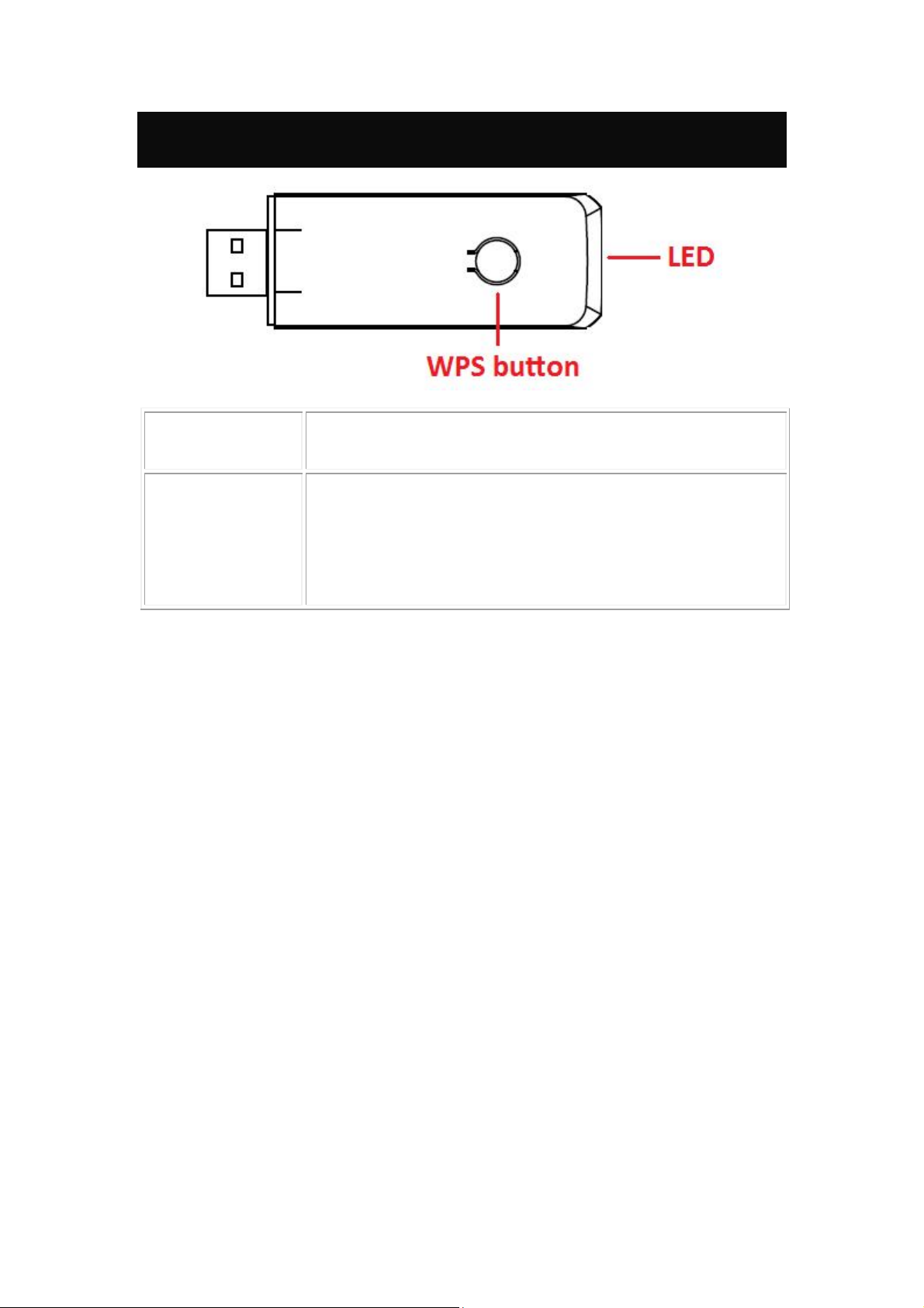
Physical Details
To press the physical WPS button on the Wireless USB Dongle once,
WPS button
LED
then the LED will start to flash. Please make a connection with another
WPS supported device within 2 minutes.
Off – Power off
Solid Green – When associate with the Access Point or Ad-Hoc wireless
workstation the LED will show solid green.
Blinking Green – Indicate the device is transmitting data through the
Access Point or Ad-Hoc wireless workstation. Also when the PBC butto n
is pressed, the LED will blink to indicate WPS status that the LED will
blink 2 seconds and off 2 seconds.
2 -
-
Page 6
Chapter 2: Installation
Install Software
Note:
Do not insert the Wireless USB Adapter into the computer until the
InstallShield Wizard finished installing.
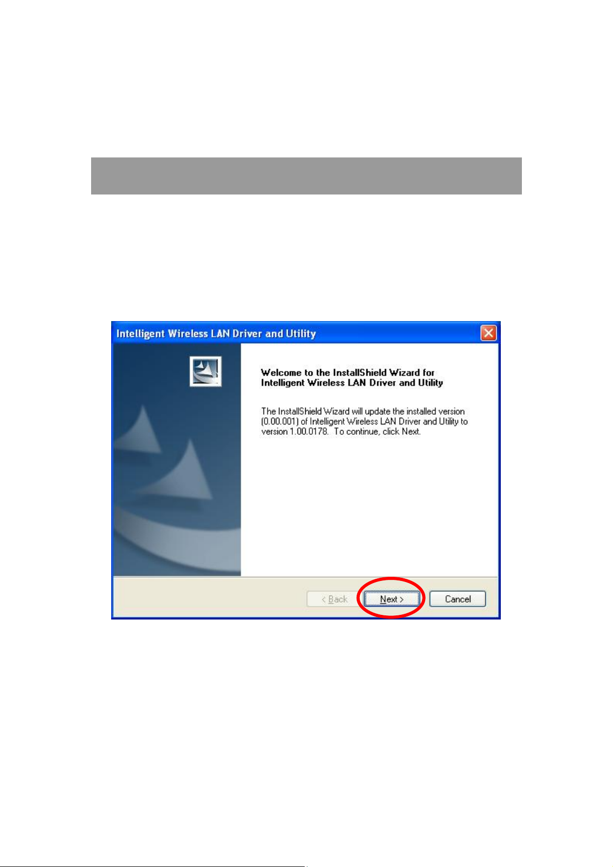
1. Exit all Windows programs. Insert the included Installation CD into the computer. The CD-ROM
will run automatically. Please click Next to process the installation.
3 -
-
Page 7
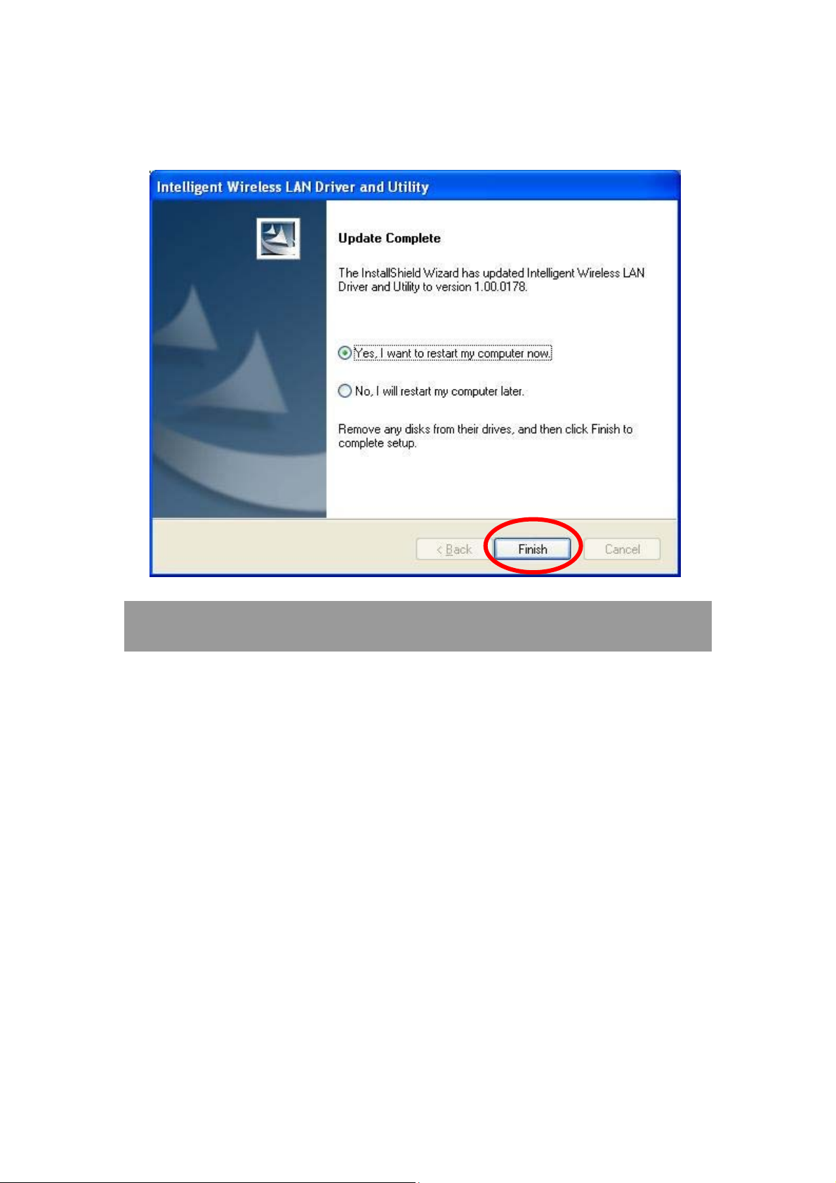
2. When the following screen appears, click Finish to restart the computer to complete the software
installation.
Install Hardware
Note:
Insert the Wireless USB Adapter when finished software installation.
Insert the Wireless USB Adapter into the USB Port of the computer. The system will automatically
detect the new hardware.
4 -
-
Page 8
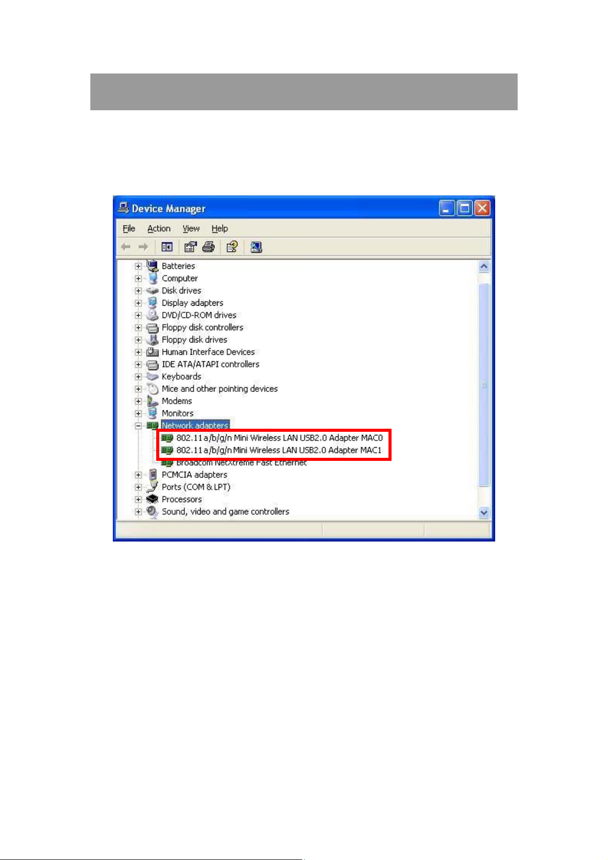
Verification
To verify the device is active in the computer. Go to Start > Control Panel > System > Hardware>
Device Manager. Expand the Network adapters category. If the 802.11a/b/g/n Mini Wireless LAN
USB2.0 Adapter MAC0/MAC1 is listed here, it means that the device is properly installed and
enabled.
5 -
-
Page 9
Chapter 3:
Network Connection
How to Make a Connection
To make a connection with an access point, please follow below steps. Here takes Windows XP OS for
example.
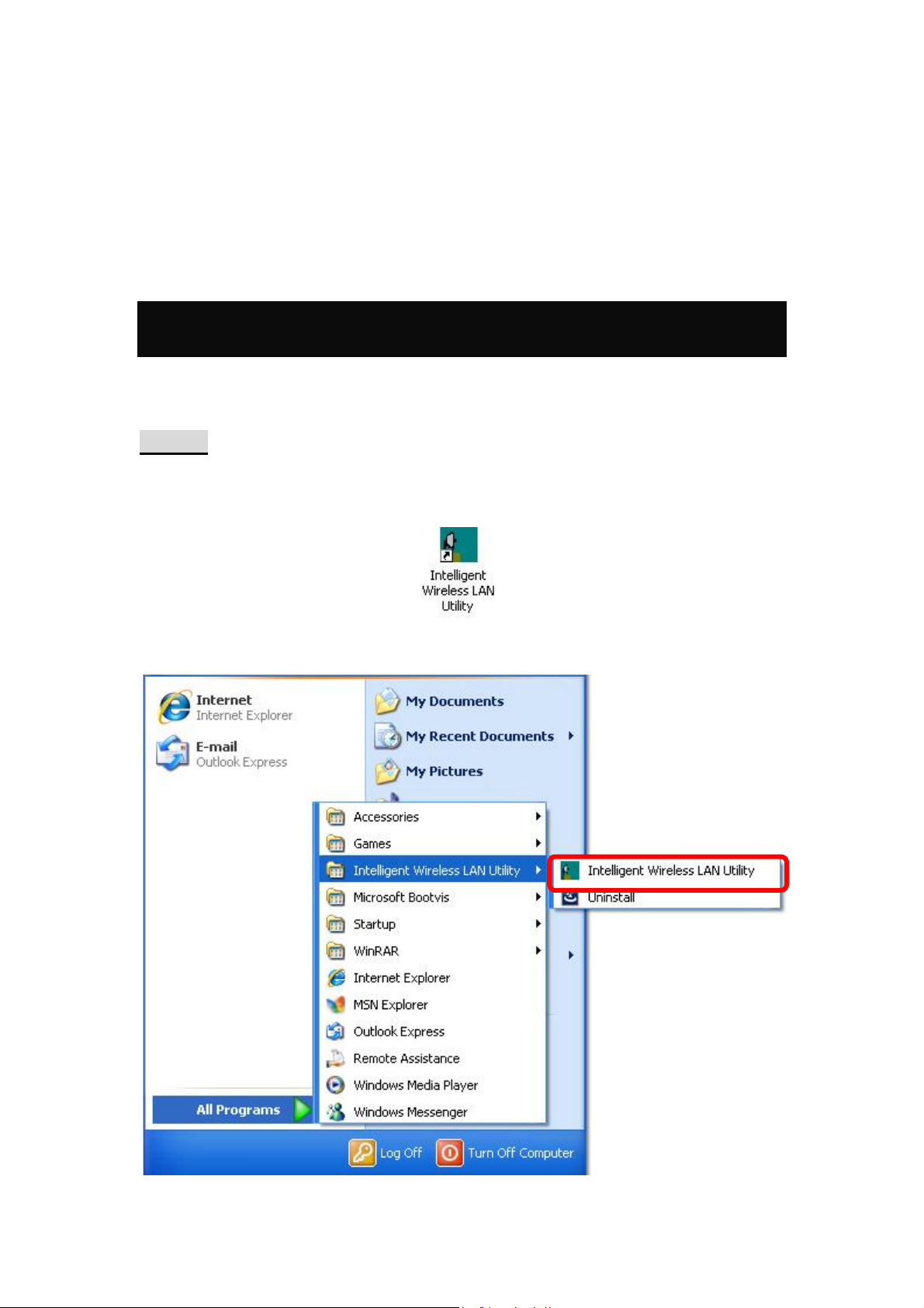
Step 1: After set up the Wireless USB Adapter successfully, please launch the Configuration
Utility. There are two ways to launch the utility by:
(1) Double clicking the Intelligent Wireless LAN Utility icon on the desktop.
(2) Or go to Start All Programs Intelligent Wireless LAN Utility Intelligent Wireless
LAN Utility.
6 -
-
Page 10

Step 2: Please go to the Available Network tab, the system will automatically scan access points
nearby, or click Refresh button to site survey again.
Step 3: Then, double click preferred access point or click Add to Profile button to make a
connection (if the access point has been set up security, please enter passwords and then click OK.)
7 -
-
Page 11

How to Add a Profile
After launched Wireless LAN Utility and selected preferred access point, please click Add to Profile
button to enter Wireless Network Properties windows. If the access point has been set up security,
please enter passwords, and then click OK to save profile settings.
After finished above settings, please go to Profile tab to check the profile listed (Available Prof ile(s)).
8 -
-
Page 12

Chapter 4:
Utility Configuration
Station Mode
Show Tray Icon: Check to show the wireless adapter icon at the tray.
Disable Adapter: Check this to disable the wireless adapter.
Radio off: Check this to turn OFF radio function.
Windows Zero Config: Click to use windows built-in wireless utility.
Close: Click to leave the Intelligent Wireless LAN Utility.
9 -
-
Page 13

General
The General page displays the detail information of current connection.
General Tab
Status
Speed
Type
Encryption
SSID
Signal Strength
Link Quality
MAC Address
IP Address
Subnet Mask
Gateway
Renew IP
Shows the current connected status. If there is no connection, it will show
Not Associated. If been connected, the system will show Associated.
When connecting, the system will show checking Status.
Shows the current transmitting rate and receiving rate.
Network type in use, Infrastructure or Ad-Hoc.
Shows the encryption type currently in use. Valid value includes WEP,
TKIP, AES, and Not Use.
Shows the connected access point network name.
Shows the receiving signal strength.
Shows the connection quality based on signal strength.
The physical address of the Wireless USB Adapter.
Shows the IP address information.
Shows the Subnet Mask information.
Shows the default gateway IP address.
Click the Renew IP button to obtain IP address form the connected
gateway.
-
10 -
Page 14

Profile
Profile can let users book keeping the favorite wireless setting among home, office, and other public
hot-spot. Users may save multiple profiles, and activate the correct one at preference. The Profile
manager enables users to Add, Remove , E dit, Duplicate and Set Default profiles.
Profile Tab
Profile Name
SSID
Add
Here shows a distinctive name of profile in this column.
The SSID is the unique name shared among all wireless access points in
the wireless network.
Click Add button to add a profile from the drop-down screen.
-
11 -
Page 15

Profile Name: Users can enter profile name at will.
Network Name (SSID): The SSID is the unique network name
(case-sensitive) shared among all wireless access points in the wireless
network. The name must be identical for all devices and wireless access
points attempting to connect to the same network.
This is a computer-to-computer (ad hoc) network; wireless access
points are not used: This function is selected to enable the ad hoc
network type that computers should be setup at the same channel to
communicate to each other directly without access point, users can share
files and printers between each PC and laptop. User can select channels
form the pull-down menu.
Wireless network security
Network Authentication: There are several types of authentication
modes including Open System, Shared Key, WPA-PSK, WPA2-PS K,
WPA 802.1X, WPA2 802.1X, WEP 802.1X.
Data encryption: For Open System, Shared Key and WEP 802.1X
authentication mode, the selection of encryption type is WEP. For
WPA-PSK, WPA2-PSK, WPA 802.1X and WPA2 802.1X authentication
mode, the encryption type supports both TKIP and AES.
When encryption is set to WEP…
ASCII: Only valid when using WEP encryption algorithm. When key
length is set to 64 bits user can enter 5 ASCII characters (case sensitive),
and 128 bits for 13 ASCII characters (case sensitive).
PASS PHRASE: Only valid when using WEP encryption algorithm.
When key length is set to 64 bits user can enter 10 Hexadecimal characters
(0~9, a~f) and 128 bits for 26 Hexadecimal characters (0~9, a~f).
Key index (advanced): Select 1~4 key index form the pull-down menu,
must match with the connected AP’s key index.
When encryption is set to WPA-PSK/ WPA2-PSK…
Network key: Enter network key at least 8 to 64 characters.
Confirm network key: Enter network key again to confirm.
12 -
-
Page 16

When encryption is set to WPA 802.1X/ WPA2 802.1X/ WEP
802.1X…
When users use radius server to authenticate client certificate for WPA
authentication mode (WPA authentication do not support EAP MethodMD5-Challenge).
EAP TYPE:
TLS: Transport Layer Security. Provides for certificate-based and
mutual authentication of the client and the network. It relies on
client-side and server-side certificates to perform authentication and
can be used to dynamically generate user-based and session-base d
WEP keys to secure subsequent communications between the WLAN
client and the access point.
LEAP: Light Extensible Authentication Protocol. It is an EAP
authentication type used primarily in Cisco Aironet WLANs. It
encrypts data transmissions using dynamically generated WEP keys,
and supports mutual authentication.
TTLS: Tunnelled Transport Layer Security. This security method
provides for certificate-based, mutual authentication of the client and
network through an encrypted channel. Unlike EAP-TLS, EAP-TTLS
requires only server-side certificates.
PEAP: Protect Extensible Authentication Protocol. PEAP transport
securely authentication data by using tunnelling between PEAP clients
and an authentication server. PEAP can authenticate wireless LAN
clients using only server-side certificates, thus simplifying the
implementation and administration of a secure wireless LAN.
MD5: Message Digest Challenge. Challenge is an EAP
authentication type that provides base-level EAP support . I t
provides for only one-way authentication - there is no mutual
authentication of wireless client and the network.
Tunnel: This is enabled under TTLS and PEAP type. For TTLS, the
selections of tunnel are CHAP, MSCHAP, MSCHAP-V2, PAP. For PEAP,
the selections of tunnel are MD5, GTC, TLS and MSCHAP-V2.
Username: Enter the username for server.
Identity: Enter the identity for server.
Domain: Enter the domain of the network.
Password: Enter the password for server.
Certificate: Choose server that issuer of certificates.
Remove
Edit
Duplicate
Set Default
Click Remove button to delete selected profile.
Click Edit button to edit selected profile.
Click Duplicate button to copy selected profile.
Click Set Default button to set selected profile to be connected first.
13 -
-
Page 17

Available Network
This page displays the information of surrounding APs from last scan result. The tab lists the
information including SSID, Channel, Encryption, Network Authentication, Signal, Type, BSSID,
Supported Rate (s), and Mode.
Network Tab
SSID
Channel
Encryption
Network
Authentication
Signal
Type
BSSID
Supported Rate(s)
Shows the network name of the access points.
Shows the currently channel in use.
Shows the encryption type currently in use. Valid value includes WEP,
TKIP, AES, None and TKIP/AES.
Show the device network authentication.
Shows transmit power, the amount of power used by a radio transceiver to
send the signal out.
Network type in use, Infrastructure or Ad-Hoc mode.
Shows Wireless MAC address.
Shows the transmitting data rate.
-
14 -
Page 18

Mode
Refresh
Add to Profile
Note
Supported wireless mode. It may support 802.11b, 802.11g and 802.11n
wireless mode.
Click Refresh button to search and rescan the available network.
Select an available network (SSID) on the list and then click Add to Profile
button to add it into the profile list.
Double click on item to join/create profile.
Status
This tab listed the information about the wireless USB adapter and connected access point.
-
15 -
Page 19

Statistics
The Statistics screen displays the statistics on the current network settings.
Statistics
Tx OK
Tx Error
Rx OK
Rx Packet Count
Rx Retry
Rx ICV Error
Reset
Shows information of packets successfully sent.
Shows information of packets failed transmit after hitting retry
limit.
Shows information of packets received successfully.
Shows information of packets received successfully.
Shows information of packets failed transmit after hitting retry
limit.
Shows information of packets received with ICV error.
Click to reset counters to zero.
-
16 -
Page 20

WPS
The primary goal of Wi-Fi Protected Setup (Wi-Fi Simple Configuration) is to simplify the security
setup and management of Wi-Fi networks. The STA as an Enrollee or external Registrar supports the
configuration setup using PIN (Personal Identification Number) configuration method or PBC (Push
Button Configuration) method through an internal or external Registrar.
WPS Tab
PIN Code
Pin Input Config
(PIN)
Push Button Config
(PBC)
8-digit numbers. It is required to enter PIN Code into Registrar when using
PIN method. When STA is Enrollee, users can use "Renew" button to
re-generate new PIN Code.
Click the Pin Input Config (PIN) button to select specific AP to process PIN
Config.
Click this button to connect with AP that supported WPS function within two
minutes. Meanwhile, the AP should also click the PBC button simultaneously.
-
17 -
Page 21

About
This page displays the information of the Wireless USB Adapter Version.
Switch to AP Mode
To access the soft AP mode, please double click the 802.11 a/b/g/n Mini Wireless LAN USB2.0
Adapter WiFi Soft AP to enter the soft AP mode setting.
-
18 -
Page 22

Soft AP mode
General
General
SSID
BSSID
Network Address
Association Table
Config
Shows the network name of the AP.
Shows the MAC address of the AP.
Shows the IP address and subnet Mask of the soft AP.
This table shows the connected client here.
Click the Config button to set up the Wireless Network Properties.
-
19 -
Page 23

Network Name (SSID): User can change the network name of this access
point.
Channel: User can select the channel form the pull-down list.
Wireless network security
Network Authentication: There are several types of authentication
modes including Open System, Shared Key, WPA-PSK and WPA2-PSK.
Data encryption: For Open System and Shared Key authentication mode,
the selection of encryption type is WEP. For WPA-PSK, WPA2-PSK,
authentication mode, the encryption type supports both TKIP and AES.
When encryption is set to WEP…
ASCII: Only valid when using WEP encryption algorithm. When key
length is set to 64 bits user can enter 5 ASCII characters (case sensitive),
and 128 bits for 13 ASCII characters (case sensitive).
PASS PHRASE: Only valid when using WEP encryption algorithm.
When key length is set to 64 bits user can enter 10 Hexadecimal characters
(0~9, a~f) and 128 bits for 26 Hexadecimal characters (0~9, a~f).
Key index (advanced): Select 1~4 key index form the pull-down menu,
must match with the connected AP’s key index.
When encryption is set to WPA-PSK/ WPA2-PSK…
Network key: Enter network key at least 8 to 64 characters.
Confirm network key: Enter network key again to confirm.
20 -
-
Page 24

Advanced
Advanced
Beacon Interval
DTIM Period
Preamble Mode
Set Defaults
Apply
The time between two beacons. (The system default is 100 ms.)
The delivery traffic indication message (DTIM) is an element included in
some beacon frames. User can specify a value from 1 to 255 beacons.
Select from the pull-down menu to change the Preamble type into Short
or Long.
Click to use the system default value.
Click to apply the above settings.
-
21 -
Page 25

Statistics
Statistics
Tx OK
Tx Error
Rx OK
Rx Packet Count
Rx Retry
Rx ICV Error
Reset
Shows information of packets successfully sent.
Shows information of packets failed transmit after hitting retry
limit.
Shows information of packets received successfully.
Shows information of packets received successfully.
Shows information of packets failed transmit after hitting retry
limit.
Shows information of packets received with ICV error.
Click to reset counters to zero.
-
22 -
Page 26

ICS
This page displays setting Internet connection sharing (ICS). Select a sharing public network and click
Apply button to make a connection.
-
23 -
Page 27

Chapter 5: Remove
To remove the utility and driver, please refer to below steps. (When removing the utility, the driver will
be removed as well.)
1. Go to Start All Programs Intelligent Wireless LAN Utility Uninstall.
-
24 -
Page 28

2. Click Yes to completely remove the selected application and all of its features.
3. Then click Finish to complete removing.
-
25 -
 Loading...