

Page 1

60GHz WirelessHD
Transceivers
User Manual
Page 2

Federal Communication Commission
Interference Statement
This device complies with Part 15 of the FCC Rules. Operation is subject to the
following two conditions: (1) this device may not cause harmful interfere nce, and (2)
this device must accept any interference received, including interference that may cause
undesired operation.
NOTE: This equipment has been tested and found to comply with the limits for a
Class B digital device, pursuant to Part 15 of the FCC Rules. These limits are designed
to provide reasonable protection against harmful interference in a residential installation.
This equipment generates uses and can radiate radio frequency energy and, if not
installed and used in accordance with the instructions, may cause harmful interference
to radio communications.
In order to comply with FCC RF Exposure requirements, a separation distance of at
least 20 cm must be maintained between the antenna an d all pe rsons.
However, there is no guarantee that interference will not occur in a particular
installation. If this equipment does cause harmful interference to radio or television
reception, which can be determined by turning the equipment off and on, the user is
encouraged to try to correct the interference by one or more of the following measures:
z Reorient or relocate the receiving antenna.
z Increase the separation between the equipment and receiver .
z Connect the equipment into an outlet on a circuit different from that to which the
receiver is needed.
z Consult the dealer or an experienced radio/TV technician for help.
Page 3

Table of Contents
CHAPTER 1: INTRODUCTION...................................................................................................................................1
OVERVIEW.......................................................................................................................................................................1
FEATURES........................................................................................................................................................................1
PACKAGE CONTENTS.........................................................................................................................................................2
APPLICATION DIAGRAM....................................................................................................................................................2
CHAPTER 2: HARDWARE INSTRUCTION.............................................................................................................3
60GHZ WIRELESSHD TRANSMITTER................................................................................................................................3
TX Front Panel Configuration
TX Rear Panel Configuration
TX Side Panel Configuration
60GHZ WIRELESSHD RECEIVER ...................................................................................................................................... 6
RX Front Panel Configuration
RX Rear Panel Configuration
RX Side Panel Configuration
REMOTE CONTROLLER......................................................................................................................................................8
CHAPTER 3: INSTALLATION.....................................................................................................................................9
SET UP STEPS..................................................................................................................................................................9
CHAPTER 4: SOFTWARE UPGRADE...................................................................................................................... 12
SOFTWARE APPLICATION INSTALLATION..........................................................................................................................12
START TO UPGRADE .......................................................................................................................................................16
CHAPTER 5: SPECIFICATIONS..............................................................................................................................19
SPECIFICATIONS.............................................................................................................................................................19
................................................................................................................................3
.................................................................................................................................4
..................................................................................................................................5
................................................................................................................................6
.................................................................................................................................7
..................................................................................................................................7
Video Format
Audio Format
.........................................................................................................................................................20
.........................................................................................................................................................20
Page 4

Chapter 1: Introduction
Overview
For coming huge flat TV screen and high definition resolution, users like to set
up the AV system in living room, but the cable placement always is a great
harassment to the interior house. Also the HDMI cable is as expensive as the length
as be. Users deserve to have a wireless cable replacement to match their high class
AV systems. Here shows up a high edge solution to meet users’ equipment: 60GHz
WirelessHD Audio-V ideo Transceivers!
This elegant product has HDMI interface to take multiple content sources like
multimedia center, Blue ray player and Set-Top Box, without compressing of content,
the WirelessHD technology will offer multiple gigabit throughout for Full HD video
transmission. Users do not need to worry about video quality for lower transmission
bandwidth anymore. It also has compliance to WirelessHD, HDMI, and DTCP for
content security and quality assurance.
Features
36 antennas array
Auto tracing - smart antenna
Least interference - 60GHz transmission
1080P 60f 50 Hz/ 59.94 Hz/ 60Hz global capability
Full HD 1080P 60f non-compressing image wireless transmission
Support HDCP/ DTCP for content security and quality assurance
4Gb/sec. wireless transmission
Multiple TX to single RX availability
1
Page 5
Package Contents
The following items should be included:
z 60GHz WirelessHD transmitter unit
z 60GHz WirelessHD receiver unit
z User manual
z Remote controller
If any of the above items are damaged or missing, please contact your dealer
immediately.
z Two-piece of HDMI cables
z Two-piece of power adapters
z Warranty leaflet
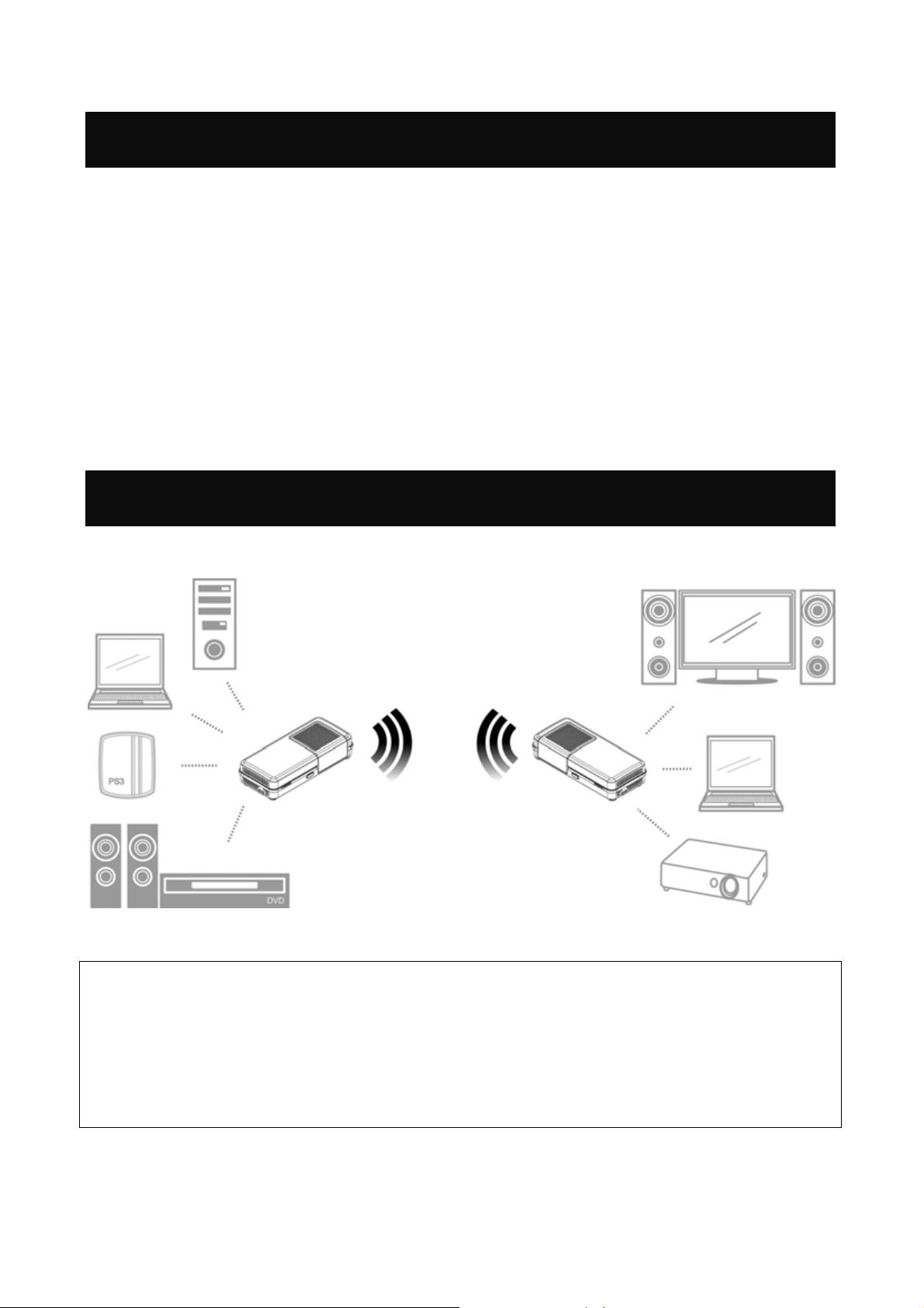
Application Diagram
Notice!
For better transmitting quality, we strongly recommend to put the
60GHz WirelessHD Transceivers horizontally in open space, do not
put them into cabinet or cupboard that will reduce the wireless
transmitting signal.
2
Page 6
Chapter 2:
Hardware Instruction
60GHz WirelessHD Transmitter
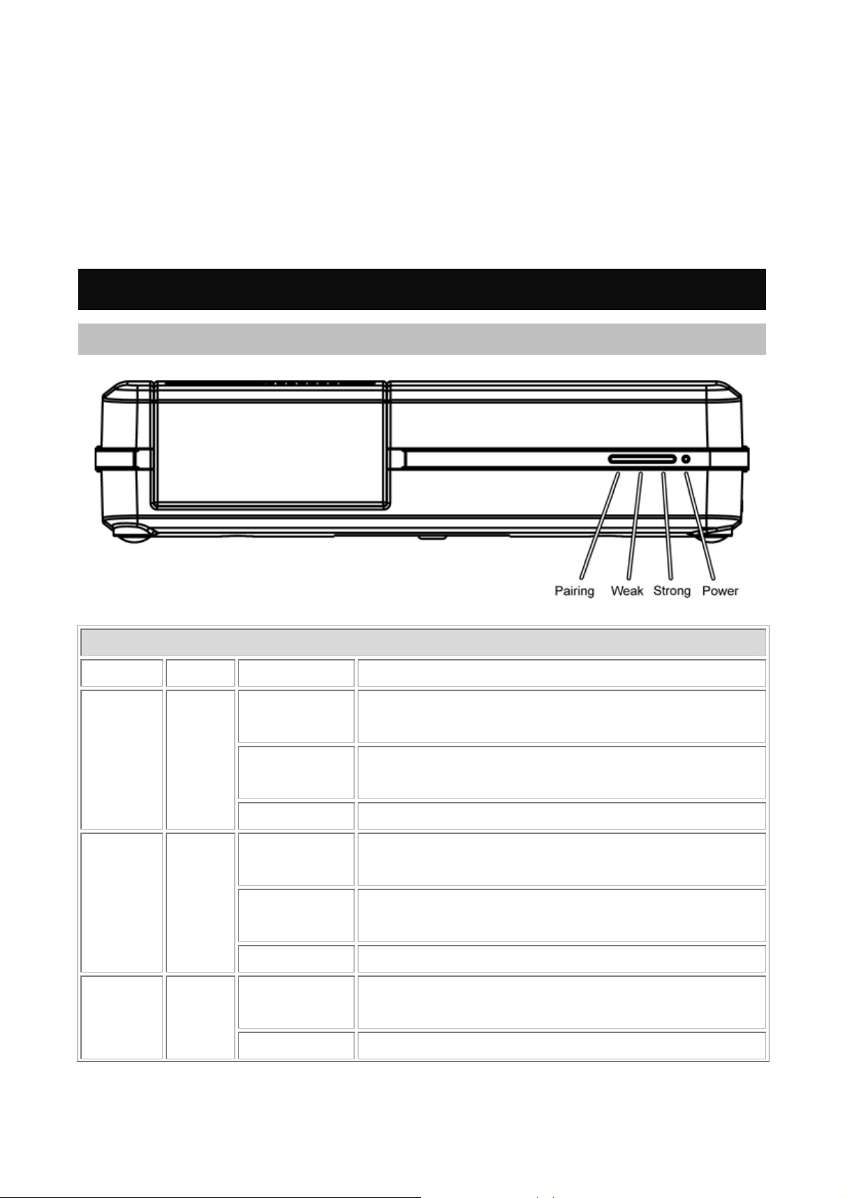
TX Front Panel Configuration
TX LED Indicators
LED Color Behavior Indication
The LED will illuminate when the power is
connected and the power switch is turned on.
The LED will be dark when the power switch is
turned off.
The LED will illuminate to indicate which RX is
being selected.
If the pairing LED is off, user has to re-select
again or reset both devices.
The LED will illuminate when the signal is
weak.
Power
Pairing
Weak
On
Green
Off
Blinking Unit in sleep mode.
On
Blue
Off
Blinking Waiting for link.
On
Green
Off No link or no signal
3
Page 7
On
The LED will illuminate when the signal is
Strong
Green
strong.
Off Signal weak
If 4 LEDs are blinking at same time, that means fan does n’t work, please turn off unit
and send to serv ice station.
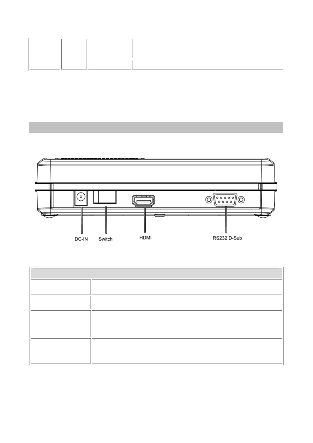
TX Rear Panel Configuration
Configuration
DC-IN
Switch
HDMI
RS232 D-Sub
Connect the power adapter to the power DC-IN port.
Switch the button to turn on or off the power supply.
Connect HDMI cable one end to this HDMI port and the other
to the DVD player or computer HDMI port.
Connect the RS232 D-Sub cable one end to this port, the other
to the computer or laptop RS232 D-Sub port.
4
Page 8

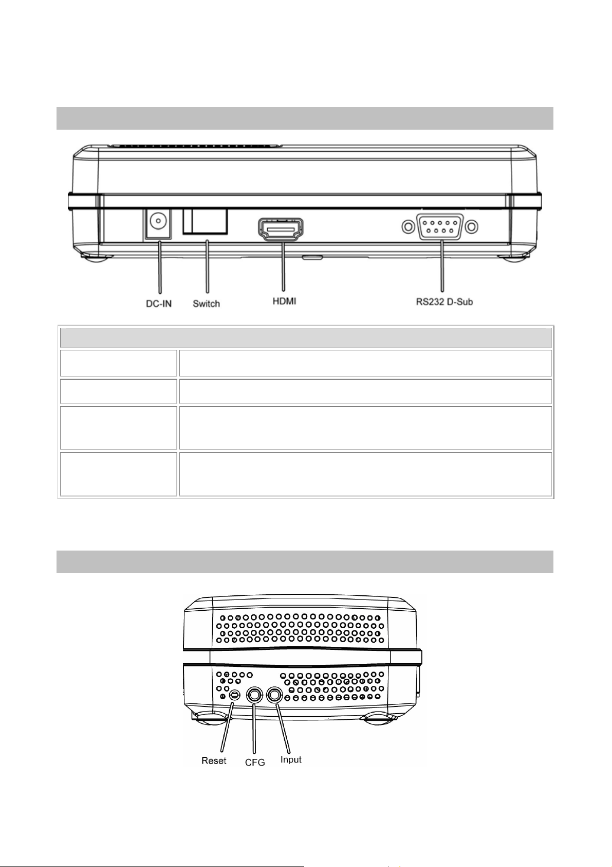
TX Side Panel Configuration
TX Buttons
Reset
CFG (Configure)
No function
Press the “RESET” button to reset the system, the
system will run through a full reset which takes
approximately 5 seconds.
This button is for upgrade system firmware. For further
firmware upgrade process, please refer to Chapter 4:
Software Upgrade.
This button is fixed and no function here.
5
Page 9

60GHz WirelessHD Receiver
RX Front Panel Configuration
RX LED Indicators
LED Color Behavior Indication
The LED will illuminate when the power is
On
connected and the power switch is turned on.
Power
Green
The LED will be dark when the power switch is
Off
turned off.
Blinking Unit in sleep mode.
The LED will illuminate to indicate which TX is
On
being selected.
Pairing
Blue
If the pairing LED is off, user has to re-select
Off
again or reset both devices.
Blinking Waiting for link.
The LED will illuminate when the signal is
On
Weak
Green
weak.
Off No link or no signal
The LED will illuminate when the signal is
On
Strong
Green
strong.
Off Signal weak
If 4 LEDs are blinking at same time, that means fan does n’t work, please turn off unit
and send to serv ice station.
6
Page 10
RX Rear Panel Configuration
Configuration
DC-IN
Switch
Connect the power adapter to the power DC-IN port.
Switch the button to turn on or off the power supply.
Connect HDMI cable one end to this HDMI port and the other
HDMI
to the TV or computer HDMI port.
Connect the RS232 D-sub cable one end to this port, the other
RS232 D-Sub
to the projector or TV RS232 D-sub port.
RX Side Panel Configuration
7
Page 11

RX Buttons
Reset
Press the “RESET” button to reset the system, the system will
run through a full reset which takes approximately 5 seconds.
Input Switch
Press the RX unit "INPUT" button repeatedly to switch to
desired source units (TX1/ TX2…) and the “PAIRING” LED
( Pending )
will illuminate to indicate which source unit is being selected.
This button is for upgrade system firmware. For further
CFG (Configure)
firmware upgrade process, please refer to Chapter 4: Software
Upgrade.
Remote Controller
Remote Controller
Stand by
Switch
( Pending )
The devices will be ready while this button clicking.
Switch the pairing input source to different 60GHz WirelessHD
Transmitters.
8
Page 12

Chapter 3: Installation
Set Up Steps
1. Connect the 60GHz WirelessHD Transmitter with cables to media input sources,
such as a computer or a DVD player.
9
Page 13

2. And connect 60GHz WirelessHD Receiver with cables to media output sources,
such as a monitor or a projector.
Notice!
Do not forget to turn on the power supplies of your monitor,
projector or video device and switch them into corresponding
settings. Such as, set your monitor sources into HDMI setting for
media receiving.
10
Page 14

3. Then, connect both power adapters of the 60GHz WirelessHD Transceivers to
outlets.
4. Turn on the power of both 60GHz WirelessHD Transceivers.
5. After finished above set up steps, the 60GHz WirelessHD T ransceivers will be
ready to transmit media.
11
Page 15

Chapter 4:
Software Upgrade
Software Application Installation
The devices would allow user to upgrade firmware into new version. Please
download the new firmware and application from the supported website. (Please fill
in the website link.) Then, install the application on your computer or laptop by the
following steps.
1. When this screen shows up, please click Next to install.
12
Page 16
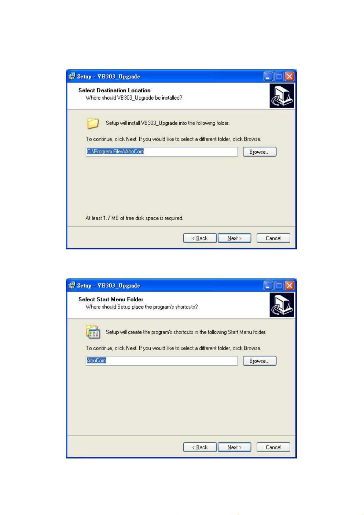
2. Select destination location, click Next to continue or click Browse to change the
location.
3. Select start menu folder, click Next to continue or click Browse to change the
folder.
4. Select to create a short cut on the desktop, and then click Next to process.
13
Page 17

5. When following screen shows up, it is ready to install the application on your
computer. Please click Install to setup.
6. The application installing is completed, click Finish to exit.
14
Page 18

15
Page 19

Start to Upgrade
1. Connect the RS232 D-Sub cable one end to device, the other to the computer or
laptop RS232 D-Sub port.
16
Page 20

2. After confirming the hardware connection, please execute the software
application that installed.
Communication
RF Board Program
(bin file)
Select the Com Port that connects the computer with RS232
D-Sub cable to the transceiver.
1. Find and open the RF firmware file by click the
button, the browser will display to correct file path.
2. Then, select the Product button to upgrade the
program.
3. The upgrade status will show in the column below of
the screen.
4. Wait for “upgrade success” message comes out from
state log area.
5. If get “fail” message from state log area, please re-do
the steps again.
6. After finished the firmware upgrade, please turn off
17
Page 21

then on the power to complete the firmware
upgrading.
Notice : User can upgrade the RF
firmware directly without pressing
CFG button.
1. Turn off the power supply first, and hold the CFG
(Configure) button on the device turning on the power
supply. Please remember to keep on holding the CFG
(Configure) button for two seconds. The LEDs will not
illuminate at this time.
2. Then, find and open the Host firmware file by click the
button, the browser will display to correct file path.
Flash Program
(hex file)
Check Host
Set Default
Cancel
3. Then, select the Upload to Flash button to upgrade the
program.
4. The upgrade status will show in the column below of the
screen.
5. Wait for “upgrade success” message comes out from state
log area.
6. If get “fail” message from state log area, please re-do the
steps again
7. After finished the firmware upgrade, please turn off then
on the power to complete the firmware upgrading.
Click this button to check the host connection status.
Click this button to set the system back to default settings.
Click Cancel to give up and exit the upgrade process.
Notice!
The Transmitter, Receiver and RF parts firmware cannot be
combined in one, thus user need to upgrade the firmware
18
Page 22

separately.
Chapter 5: Specifications
Specifications
Standards
Frequency
Input/ Output
Interface
Antenna Type
Range
AV Port
Physical
Specifications
Adapter Power AC 90-230V @ 60Hz input, DC 12V 1.5A
WirelessHD
60 GHz
HDMI Interface
36 Antenna Array (Integrate Ceramic)
10 meters indoors
Transmitter : 1 Port (HDMI 1.3)
Receiver : 1 Port (HDMI 1.3)
Weight: 324g±10g
Dimension: 183 (L) x 80 (W) x 36 (H) mm
Transmitter: Four LEDs display, power, pairing
LED Indicators
indicator, signal Strength indication
Receiver : Four LEDs display, power, pairing indicator,
signal Strength indication, IR sensor
19
Page 23

Operating Temperature: 0 ~ 50 ambient temperature℃
Operating
Environment
(Total System)
I/O Port
Video Format
(CEA-861 Code)
640x480p (1)
Except AC adaptor, it is only 0 ~ 40℃
Storage Temperature: -30 ~ 70℃
Operating Humidity: 10% to 90% (Non-condensing)
Storage Humidity: 5% to 90% (Non-condensing)
RS232 Interface
Vertical Refresh Rate Resolution Format
24 Hz 50 Hz 59.94 Hz 60 Hz
25.175 MHz 25 MHz
720x480p (2/3)
720x576p (17/18)
1280x720p (19)
1280x720p (4)
1920x1080i (20)
1920x1080i (5)
1920x1080p (32) 74.25 MHz
1920x1080p (31)
1920x1080p (16)
27 MHz
27 MHz
74.25 MHz
74.176 MHz 74.25 MHz
74.25 MHz
74.176 MHz 74.25 MHz
148.5 MHz
148.352 MHz 148.5 MHz
1. Specific format support is dependent on latest firmware release.
2. Deep color (10/12-bit/per color 4:4:4) is possible for all format but resolution
1080p (not supported in WirelessHD v1.0 specification).
3. Other video formats are possible to include PC formats (VGA, XGA, SXGA, etc.)
Audio Format
Audio up to 8-ch., 24-bit 192 kHz LPCM.
20
Page 24

Multiples of Fs 32 kHz 44.1 kHz 48 kHz 88.2 kHz 96 kHz 176.4 kHz 1
9
2
4
128
256 8.192 11.290 12.288 22.579 24.576 45.158
512 16.384 22.579 24.576 45.158 49.152
4.096 5.645 6.144 11.290 12.288
Specific format support dependent on latest code release .
22.579
21
 Loading...