


This device complies with Part 15 of the FCC Rules. Operation is subject to the following two
Conditions
(1) This device may not cause harmful interference, and
(2) This device must accept any interference received, including interference that may cause
undesired operation.
■Product Name
2.4GHz ISM RF Module
■Model Name
RFAN4
■Antenna choice
Dipole ANT:Short SW1
Chip ANT:Open SW1
■Mode switch
Setp1.Enter FCC Mode
When plugged, the green led is on, the red led will be on and the green led will turn off
after pressing SW3 for 5~6 seconds. Indicating the module has entered FCC mode.
Setp2. Pattern switch
Mode
1 Press SW3 1 time Red led flash 1 time Low freq. Singleton 2402MHz
2 Press SW3 2 times Red led flashes 2 times Middle freq. Singleton 2442MHz
3 Press SW3 3 times Red led flashes 3 times High freq. Singleton 2480MHz
4 Press SW3 4 times
5 Press SW3 5 times
6 Press SW3 6 times
7 Press SW3 7 times
8 Press SW3 8 times
Operation LED Type Note
Green led on
Low freq. Carrier+Data
Red led flashes 4 times
Green led on
Middle freq. Carrier+Data
Red led flashes 5 times
Green led on
High freq. Carrier+Data
Red led flashes 6 times
Yellow led on
Low freq. RX Mode 2402MHz
Red led flash 1 time
Yellow led on
Middle freq. RX Mode 2442MHz
Red led flashes 2 times
2402MHz、MSK
2442MHz、MSK
2480MHz、MSK
9 Press SW3 9 times
The above steps worked loopwise. When pressed SW3 10 times, it will return to Mode1.
Yellow led on
High freq. RX Mode 2480MHz
Red led flashes 3 times
PDF 檔案使用 "pdfFactory Pro" 試用版本建立 www.ahasoft.com.tw/FinePrint
Remark:
The changes or modifications not expressly approved by the party responsible for compliance
could void the user’s authority to operate the equipment.
To comply with the FCC RF exposure compliance requirements, this device and its antenna
must not be co-located or operating to conjunction with any other antenna or transmitter.
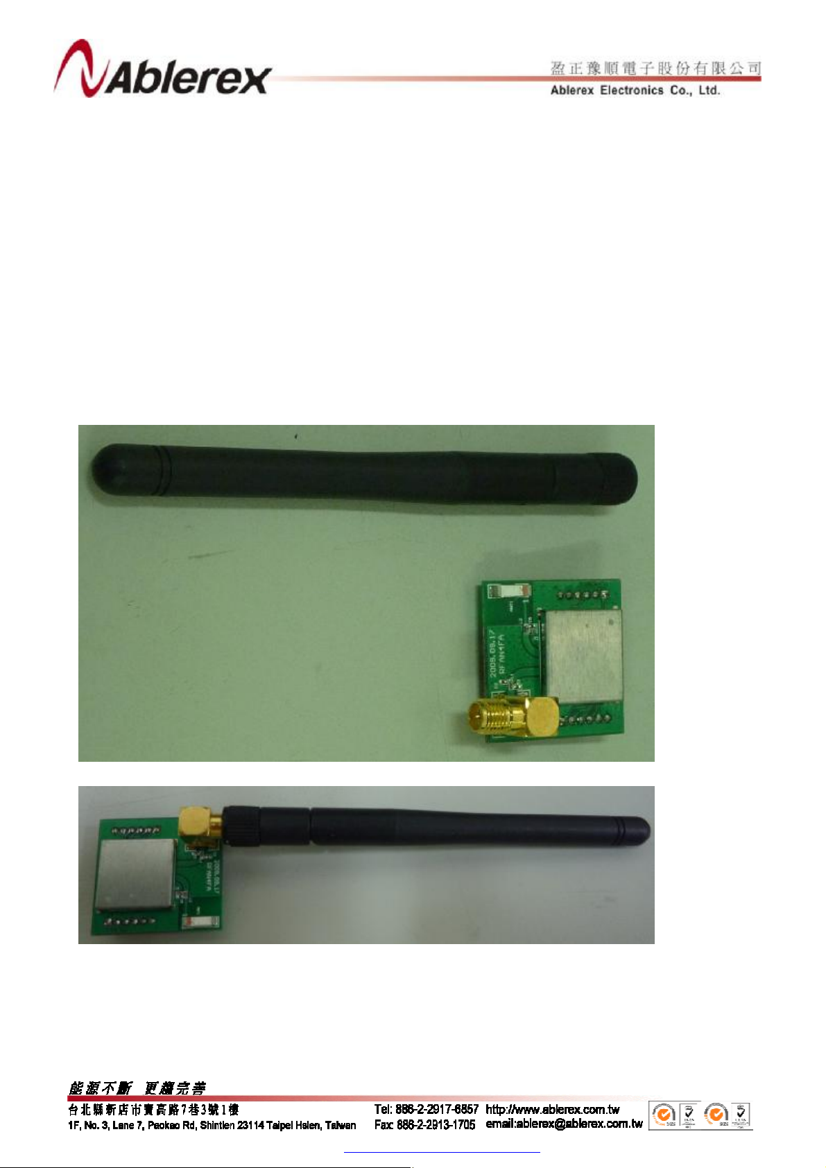
■Installation Guide
l Antenna Connection
Rotate Clockwise in order to fix the antenna into the RF module SMA connector ( Figure
1 show the golden connector head),Figure 2 show the completed antenna connection
Figure 1
Figure 2
PDF 檔案使用 "pdfFactory Pro" 試用版本建立 www.ahasoft.com.tw/FinePrint

l Fixing the Module on the System Board
Fix and connect the female pheader of the RF Module and the pin header of the System Board
(SMA connector must face outward), Figure 4 show the completed connection.
Figure 3
Figure 4
PDF 檔案使用 "pdfFactory Pro" 試用版本建立 www.ahasoft.com.tw/FinePrint
 Loading...