

Page 1
Version
Datum
Name
Kommentar
1.00
25.03.2015
ORD
CS447 hinzugefügt; 04.5 und 09 nachgearbeitet
1.00
15.04.2015
ORD
10 Fertigung aktualisiert; CS335 hinzugefügt
1.00
05.05.2015
FRM
9:Firmwareversionen STD 3 02N-R & 04.5.2 geändert
1.00
22.06.2015
FRM
9:Firmwareversionen STD 3 02N-R (335, 429 &447)
geändert
1.00
06.10.2015
FRM
04.5.x: FCC & IC Zulassungsnummern hinzugefügt
09.1: SW1 geändert
1.00
16.11.2015
FRM
04.5.3: Frequenz Kanal 20&21 getauscht.
1.00
17.11.2015
FRM
04.5.3: Frequenz & Kanäle 20 & 21 angep ass t.
04.5.10: Gruppe 5-8 geändert.
1.00
21.01.2016
FRM
04.5.1: Frequenzliste geändert
1.00
19.05.2016
KÖM
Generelle Überarbeitung
1.00
04.11.2016
KÖM
Überarbeitung im Zug der Umstel lung auf STD-302-S
1.00
15.03.2017
KÖM
10.1.1: Zusatzinfo für Verguss ergänzt
1.00
11.04.2017
KÖM
04.5 und 05.4: Zulassungen aktualisiert
1.00
25.07.2019
MK
04.5.11 CS456 hinzugef ügt ;
1.00
03.12.2019
KL
Integration Instructions
Technical
Documentation
RF Transceiver Transmitter
CSxxxTRT-1-1
with Feedback Function
KH62400061.A, K500267 &
KH66983xxx61.A, K750172
© by ABITRON Control Systems GmbH
ABITRON Control Systems GmbH
Wiesnerstraße 20
A-4950 Altheim
Page 2

erstellt:
geändert:
HF Transceiver Sender CSxxxTRT-1-1
ORD
MK
mit Rückmelde-Funktion
Datum:
02.02.2015
25.07.2019
Art.-Nr.:
KH66983xxx61.A
Seite 2 von 9
01 Description
The CSxxxTRT-1-1 RF part is a transceiver with multiple functions:
1. Transmitting or Receiving (simplex or halfduplex)
2. “Feedback Master” or “-Slave” for 3 LED-Feedback (halfduplex).
The functions are selectable by SIP-Switch for frequency allocations and solder jumper to select
Transmitter/Receiver, FB-Master or FB-Slave.
The TRT (CSxxxTRT-1-1) has four holes to be mounted on screw bosses or it is mounted in
module slots in transmitter housings.
The counterpart of the TRT is the TRR (CSxxxTRR) module which is formed to be used in
receivers.
The TRT has an ISP port (In System Programming) which makes it possible to download new
firmware.
This device complies with part 15 of the FCC Rules. Operation is subject to the following two
conditions:
(1) This device may not cause harmful interference, and (2) this device must accept any
interference received, including interference that may cause undesired operation. Changes or
modifications not expressly approved by the party responsible for compliance could void the user's
authority to operate the equipment.
(2) NOTE: This equipment has been tested and found to comply with the limits for a Class B
digital device pursuant to Part 15 of the FCC Rules. These limits are designed to provide
reasonable protection against harmful interference in a residential installation. This equipment
generates, uses, and can radiate radio frequency energy and, if not installed and used in
accordance with the instructions, may cause harmful interference to radio communications.
However, there is no guarantee that interference will not occur in a particular installation. If this
equipment does cause harmful interference to radio or television reception, which can be
determined by turning the equipment off and on, the user is encouraged to try and correct the
interference by one or more of the following measures:
‐Reorient or relocate the receiving antenna.
‐Increase the separation between the equipment and the receiver.
‐Connect the equipment into an outlet on a circuit different from that to which the receiver is
connected.
‐RF Radiation Hazard Warning (products with activated transmit option only): To ensure
compliance with FCC RF exposure requirements, this product should be positioned no less than 20
cm from your body or nearby persons during continuous use.
Name:
Page 3
erstellt:
geändert:
HF Transceiver Sender CSxxxTRT-1-1
ORD
MK
mit Rückmelde-Funktion
Datum:
02.02.2015
25.07.2019
Art.-Nr.:
KH66983xxx61.A
Seite 3 von 9
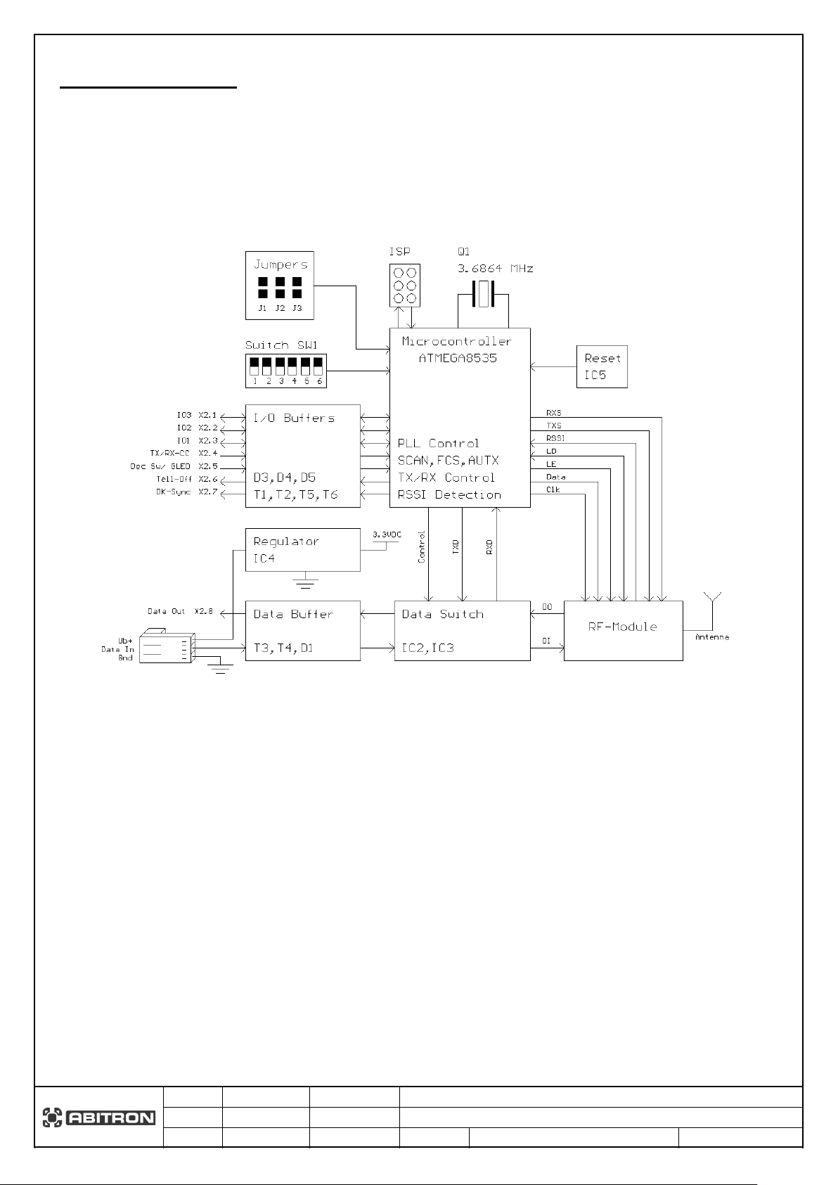
02 Block Diagram
Name:
Page 4

erstellt:
geändert:
HF Transceiver Sender CSxxxTRT-1-1
ORD
MK
mit Rückmelde-Funktion
Datum:
02.02.2015
25.07.2019
Art.-Nr.:
KH66983xxx61.A
Seite 4 von 9
03 Technical Data
Supply voltage:
3,4-12 VDC (recommended 3.4-5VDC)
Current consumption:
<50 mA
TTL Data (Open drain with 4.7K pull up)
DK-Sync (Open drain with 4.7K pull up)
Telegram-Off (Open drain with 10K pull up)
3xIO, LEDs can be connected directly
Antenna (use 50 Ohm antenna)
3xIO can be used as Inputs, Level 0 / 5V (higher values
possible with additional series resistor).
Frequency change („Dec“)-Input / Green LED (0-12V)
TX/RX-Switch (0-12V)
Antenna (use 50 Ohm antenna)
TTL Data (0-5V level) 2400-9600 Ba ud
Temperature range:
-20o C to 70o C
TX to RX or RX to TX
20mS for temperature –20° to 70° C
Modulation:
FSK Narrow
Outputs:
Inputs:
Switching time:
10mS for temperature –10° to 50° C
The CSxxxTRT can work with the following baud rates (depending on frequency band):
Notice:
It is recommended to use 3.4-5VDC power supply to reduce heat dissipation if available.
If module is used in automatic mode the decrement channel switch should be interlocked
with the STOP switch so that it is not possible to change channel during normal operation.
This way the channel change can only be done when the system is in STOP condition and
an accidental channel change in normal conditions is prevented.
Name:
Page 5

erstellt:
geändert:
HF Transceiver Sender CSxxxTRT-1-1
ORD
MK
mit Rückmelde-Funktion
Datum:
02.02.2015
25.07.2019
Art.-Nr.:
KH66983xxx61.A
Seite 5 von 9
04 Connection
CSxxxTRT-1 as transmitter
CSxxxTRT-1 as Receiver
To change the frequency via a button connected to the decrement input of the
J1, J2 & J3 = open
J1, J2 & J3 = open
0V/GND
offen/open/High
04.1 Standard Connection
04.2 Modes
04.2.1 Connection as Transmitter or Receiver
TRT module, press this button for at least 2 seconds!
Name:
Page 6

erstellt:
geändert:
HF Transceiver Sender CSxxxTRT-1-1
ORD
MK
mit Rückmelde-Funktion
Datum:
02.02.2015
25.07.2019
Art.-Nr.:
KH66983xxx61.A
Seite 6 von 9
Set the coder Baudrate to 4800 if
04.2.2 Connection as Feedback Master (Control Side)
J1 & J2 = closed
J1 = closed
the TRT is used as feedback
master or slave!
J2 & J3 = open
04.2.3 Connection as Feedback Slave (Machine Side)
Name:
J3 = open
Page 7

erstellt:
geändert:
HF Transceiver Sender CSxxxTRT-1-1
ORD
MK
mit Rückmelde-Funktion
Datum:
02.02.2015
25.07.2019
Art.-Nr.:
KH66983xxx61.A
Seite 7 von 9
04.3 Jumper Setting
J1
J2
J3
Function
Open
Open
Open
Normal
Closed
Open
Open
FB-Master
Closed
Closed
Open
FB-Slave
Standard Setting = grey background
J3 = reserved
Close J1, J2 & J3 for Test mode.
04.4 Application Note
04.4.1 FCC/IC
If the used RF part has a FCC/IC certification the certification number has to be written on the
outside of the device.
Beware:
Any modification of the RF part can void the certification!
Name:
Page 8

erstellt:
geändert:
HF Transceiver Sender CSxxxTRT-1-1
ORD
MK
mit Rückmelde-Funktion
Datum:
02.02.2015
25.07.2019
Art.-Nr.:
KH66983xxx61.A
Seite 8 von 9
04.5.11 CS456TRT-1
Automatic Setting
S1=1
D2
D3
Mode
0
0
Invalid – don´t use
TX: AUTX („Auto Channel Change“)
RX: Scan-Mode
TX: FCS („Free Channel Search“)
RX: Scan-Mode
1
1
Invalid – don´t use **
Manual Setting
S1=0
Ch.
-No.
0 0 0 0 0
456,300
00 0 0 0 0 1 456,325
01
0 0 0 1 0
456,350
02 0 0 0 1 1 456,400
03 0 0 1 0 0 456,450
04 0 0 1 0 1 456,500
05
0 0 1 1 0
456,725
06
0 0 1 1 1
456,775
07 0 1 0 0 0 456,850
08 0 1 0 0 1 456,875
09 0 1 0 1 0 456,900
10 0 1 0 1 1 456,925
11 0 1 1 0 0 456,950
12 0 1 1 0 1 457,000
13 0 1 1 1 0 457,050
14 0 1 1 1 1 457,075
15 1 0 0 0 0 457,100
16 1 0 0 0 1 457,150
17 1 0 0 1 0 457,175
18 1 0 0 1 1 457,200
19 1 0 1 0 0 457,250
20 1 0 1 0 1 457,275
21 1 0 1 1 0 457,300
22 1 0 1 1 1 457,350
23 1 1 0 0 0 457,400
24 1 1 0 0 1 457,450
25 1 1 0 1 0 457,500
26 1 1 0 1 1 457,625
27 1 1 1 0 0 457,675
28 1 1 1 0 1 457,700
29 1 1 1 1 0 457,750
30 1 1 1 1 1 457,800
31
D4
D5
D6
Channels
Gr.No.
0
0
0
1
0
0
1
3, 7, 13, 19, 24, 28
2
0 1 0
2, 6, 12, 17, 23, 27
3
0
1
1
4, 8, 14, 20, 25, 30
4
0, 2, 3, 4, 5, 6, 7, 8, 10, 12, 13,
26, 27, 28, 30, 31
1
0
1
1, 9, 11, 15, 18, 21, 29
6 1 1
0
n.u.
7 1 1
1
n.u.
8
Certification Number
Channels
USA
FCC-ID:
2AC8P-456TR1
all
Firmware-Version: CS456TRT-1K2_190723
D2 D3 D4 D5 D6 Freq. (MHz)
0 1
1 0
1 0 0
** if used as onboard RF-Part: if all switches (S1, D2, D3, D4, D5 and D6) are set to “1” ->
frequency setting is done by the software of the mainboard.
0, 5, 10, 16, 22, 26, 31
14, 16, 17, 19, 20, 22, 23, 24, 25,
5
Name:
Page 9

erstellt:
geändert:
HF Transceiver Sender CSxxxTRT-1-1
ORD
MK
mit Rückmelde-Funktion
Datum:
02.02.2015
25.07.2019
Art.-Nr.:
KH66983xxx61.A
Seite 9 von 9
05 Integration instructions for host produc t manufacturers according to KDB 996369 D03 OEM Manual v01
2.2 List of applicable FCC rules
Part 90
2.3 Specific operational use conditions
This module is approved for use in portable and mobile applications. Integrators must supply
operating instructions for end users and installers to satisfy RF exposure compliance requirements
are met. Integrators and installers must also make sure that compliance with Part 15B are ensured.
2.4 Limited module procedures
N/A, this module is not compliant with Chapter (b) from §15.212.
2.5 Trace antenna designs
N/A, the module does not use a trace antenna, it uses an external dipole antenna.
2.6 RF exposure considerations
WARNING: The 456TR1 device radiates radio frequency energy at a level below the United
States FCC radio frequency exposure limits. Nevertheless, this device should be used in such a
manner that the potential for human contact during normal operation is minimized. However, the
OEM integrator is still responsible for testing their end-product for any additional compliance
requirements required with this module installed (for example, digital device emissions, PC
peripheral requirements, etc.).
2.7 Antennas
Antenna is named with IANT419458. It´s a168mm long wire antenna with a MMCX-Connector
and connected to the RF-part CS456 TRT-1
Name:
Page 10

erstellt:
geändert:
HF Transceiver Sender CSxxxTRT-1-1
ORD
MK
mit Rückmelde-Funktion
Datum:
02.02.2015
25.07.2019
Art.-Nr.:
KH66983xxx61.A
Seite 10 von 9
2.8 Label and compliance information
The 456TR1 module is labelled with its own FCC ID. If the FCC ID is not visible when the
module is installed inside another device, then the outside of the device into which the module is
installed must also display a physical label or eLabel referring to the enclosed module. In that case
the end product must be labelled in a visible area with the following: Contains
FCC ID: 2AC8P-456TR1.
Name:
 Loading...