

Page 1
Wireless Digital Video Baby Monitor
Copyright by ABELTECH Co., Ltd All Rights reserved
USERS MANUAL
Page 2

Page 3

INDEX
I. Index
II. Package Contents
III. Caution
IV. Parent Unit
1. Parent unit Introduction
2. Control (PU)
3. LED Define
4. Set up (PU)
5. PU Monitor Introduction
6. API Menu Control
7. Menu Structure
V. Baby Unit
1. Baby unit Introduction
2. Set up (BU)
VI. Trouble Shooting
01
02
02
03
03
04
05
05
06
07
08
09
09
09
11
01
Page 4
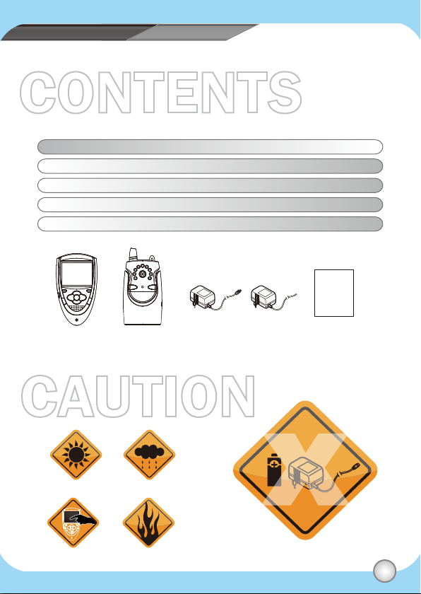
PACKAGE CONTENT CAUTION
CONTENTS
Item Description Quantity
PU Parent Unit 1 pc
BU Baby Unit 1 pc
Power Adaptor 7.5V/800mA 2 pc
User Manual 1 pc
Parent Unit
(PU)
Baby Unit
(BU)
CAUTION
No Sunshine No Water
Do not touch the panel No Fire
Adaptor 7.5V x 2 Users Manual
A6 size
Do not put the disposable batteries
and DC adoptor at the same time
02
Page 5
PARENT UNIT
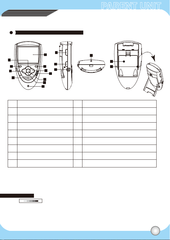
Parent Unit (PU) Introduction
A
B
C
D
Front view Side view
E
F
G
I
J
K
L
M
N
H
O
P
Q
Bottom view
Back view
A
UP / Volume + (For PU)
B
Power LED/Matching light
C
LEFT / Zoom
Speaker
D
2.46“ Panel (refer to Page 6)
E
VOX LED
F
RIGHT / VOX
G
Menu / Quit
H
※ Sound volume can be set from 0-7. (7 is Max)---PU
※ For the BU, please go to the menu mode to adjust its volume.
Sound level can be set from 0-6 (6 is Max).
※ Walkie Talkie can’t work during matching, and it also can’t talk without finishing matching.
※ VOX mode: The panel of PU side will be shut down and mute when entering the VOX mode.
1. The higher value setting means the PU side enters the VOX mode easier.
(The BU side needs get louder sound to quit the VOX mode, and vice versa.)
2. PU will be mote automatically after 20 seconds then panel will be shut dowm after 10 seconds
without triggering. Pressing any key or alarm triggered will be back to normal mode.
HL
I
ENTER / Matching
J
DOWN / Volume – (For PU)
K
Microphone
Walkie Talkie: Press it then talk to BU
L
Power button (ON / OFF)
M
DC Jack
N
Microphone
O
Battery container
P
Parent holder
Q
03
Page 6
CONTENTPARENT UNIT
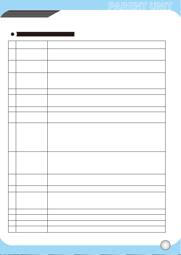
Control (PU)
Item Description
A
UP
Volume +
B
Power LED
Matching light
C
LEFT
Zoom
D
Speaker
E
Panel
F
VOX LED
G
RIGHT
VOX
H
Menu
Quit
I
ENTER
Matching
J
DOWN
Volume –
K
Microphone
L
Walkie Talkie
M
Power
N
DC Jack
P
Battery container
Q
Parent holder
UP: In Menu mode,press “UP” to choose function.
Volume: In Video mode, press “Vol +” to increase volume.
Power LED: Show the power status (please refer to the page 5).
Matching light: It will flash when matching with Baby unit.
LEFT: In Menu mode,press “LEFT” to choose function.
Zoom: Press it for zooming in twice, press it again back to
Normal size.
Can hear the baby crying sound.
Panel active area: It shows the status of volume, Temperature,
RF Link Quality, Countdown, Power for PU and BU and Main Menu.
LED ON / OFF => The function is open / close.
RIGHT: In Menu mode,press “RIGHT” to choose function.
VOX :Press VOX for 3 seconds for opening or closing this function.
Menu mode: A= UP, C= LEFT, I= ENTER, G= RIGHT, J= DOWN
(When entering into the second level, press “H” go back to the first level)
Out of Menu mode:
A= Volume +, C=Zoom, I= Maching , G= VOX ,J= Volume –
Quit: exit and back to the previous page
Enter: In menu mode, choose the function then press
“ENTER” to next page.
Matching: press it for 2 seconds,then matching light
will flash until the matching work is finished.
Down: In Menu mode,press “DOWN” to choose function.
Volume -: In Video mode, press “Vol -” to decrease volume.
Microphone: can talk to Baby unit.
Press it to talk to Baby unit.
(Walkie Talkie can’t work during matching, and it also can’t talk
without finishing matching.)
Press it to power on the device.
Plug the power adaptor .
Put the triple A batterties 2 pcs to the container.
Rotate it to a proper angle to stand.
04
Page 7

API MENU
PARENT UNIT
LED Define
OFF Green Flash Green Flash RedRed
Power
Match
VOX
Adaptor only
Green: Power on
Balck: Power off
Light Flash: matching
Stop flashing and light in Green: matching finished (panel starts to display camera of BU side)
LED ON: VOX mode is opened.
LED OFF: VOX mode is closed.
Battery only
Green: Power on
(after pressing the power button)
Flash in Red Green: Low power
Balck: out of power or power off
Set Up
Installation
1. Power on:
* Plug adaptor only: The power light won’t be lighted when the
N
power adaptor is not plugged in.
(green light when pressing the power button with beep sound once).
* Plug Battery only:
a. The power light will flash in Red and Green if the device is low power.
b. Then press the power button for beep sound once and green light to power on the device.
2. Press the power button to power on thte device.
3. Pairing:
Keep pressing PU and BU’s matching keys for 2 seconds. Then, the matching lights will
flash in red until the matching work is finished with lighting green.
4. Panel View:
Press the Menu button then referring to the next page.
05
Page 8

PARENT UNIT
PU Monitor Introduction
RF Quality
Volume display
(BU)
Date
2010/07/20
Battery Status
(PU Side)
Zoom Icon
Panel active
area
10:26
Temperature
(BU Side)
25℃Zoom
Time
Battery Status
(BU Side)
Volume setting
(PU)
Count Down
Timer
Battery Status
Date
Temperature
RF Quality
Panel Active Area
Volume Display(BU)
Volume Setting(PU)
Zoom
Time
Count Down Timer
Power indication
Full power
Run out power
Empty power
When the power is low, it will flash.(refer to as follows form)
Show the date. (please go to the menu to set up the correct date.)
Open the Temp alarm. When the temperature is out of range, the icon flash in red and beep.
When the RF signal is weak, the icon will flash in red ( ), and beep.
Show the Menu setting and BU video, start VOX Mode then it goes to Sleeping Mode.
Show the volume level of BU.
Press the vol+ or vol- button to adjust the volume of PU.
Press the hot key Zoom in to twice, and it shows the red icon, press again then invisible.
Show the real time (please go to the menu to set up the correct date.)
Menu-> Alarm Setting->Count Down-> ->set hour->
The icon keeps flashing in red and beeps when time is up.
(press any key to stop the alarm)
EX: Menu-> Alarm Setting->Count Down-> -> The icon will disappear.
Black Red
The power indication is Black.
The power indication turns into Black Red once.
The power light flash in Green Red once.
The power indication turns into Black Red until baby monitor off.
The power light flash in Green Red until baby monitor off.
06
Page 9

PARENT UNIT
API Menu Control
Press “Menu” Button
2010 / 01 / 04
00:00
OFF
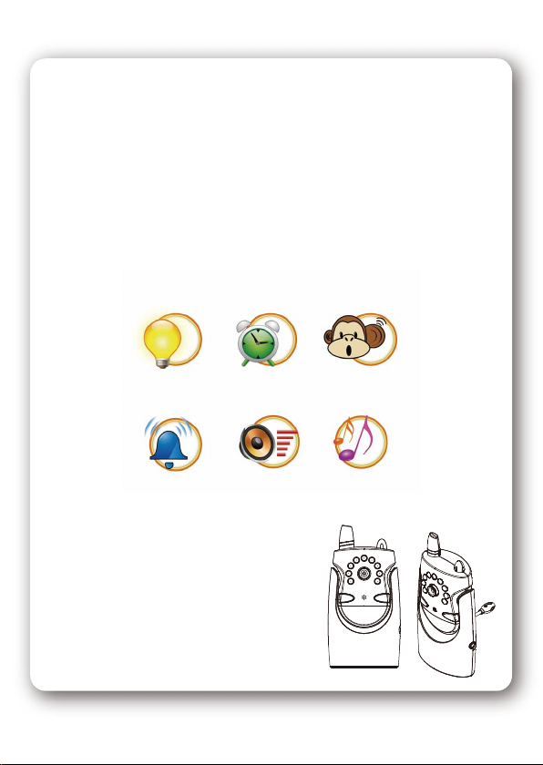
Night Light
Soothing light 1
Soothing light 2
Soothing light 3
Adjust the illumination of panel
Set the date and time
Adjust VOX sensibility
Set alarm, temperature, VOX and countdown
Adjust the volume
Setting the soothing light , night light with music
Press Left and Right button then press “ENTER” to
select the brightness.
Press Left , Right , UP and Down button then press “ENTER”
to select the Date and Time.
Press Left , Right , UP and Down button then press “ENTER”
HL
to select the sensitivity.
Press Left , Right , UP and Down
button then press “ENTER”
to select the function.
0.5HR
Press Left and Right button then press “ENTER”
to select the volume.
Press Left and Right button then press “ENTER”
to select the LED light.
(every soothing light effects will be with lovely musics)
(0.5~12HR)
07
Page 10

PARENT UNIT
Main Menu Structure
Brightness
MENU
Clock Setup
VOX Sensitivity
Alarm Setup
Volume
Soothing Light
Date
Time
Temp
VOX
Countdown
Night Light
Soothing Light 1
Soothing Light 2
Soothing Light 3
Year / Month / Date
00:00
(Hour:Minute)
HL
0.5HR
OFF
(0.5~12HR)
08
Page 11

BABY UNIT
Baby Unit Introduction
A
G
Front view
Item Description
A
Antenna
B
IR LED (night vision)
C
Camera
D
Page(matching)
E
Microphone
F
Soothing light/night light
G
Soothing light control button
H
DC Jack
I
Temperature detector
J
Speaker
K
Matching light / Power LED
L
Power button
B
C
D
E
F
H
Side view
J
K
L
I
Back view Bottom view
Send the signal of BU side to the PU side.
To adjust the light; the LED opens when the the light is insufficient.
Take the video then transmitting it to the PU side.
(1) Press for 2 seconds to match to PU side.(matching button)
(2) Press then PU side will beep to alarm the parent.
(press any key to stop the beep sound)
Talk to PU side
There are five effects of LED light.(including “night light” and “off”)
Press it to the next soothing light effect.
Plug the power Jack.
Can detect the temperature and send the data to PU side.
Can hear the voice from PU side.
The status of power and matching light.
Press it to power on the BU device.
09
Page 12

BABY UNIT
Set Up
Installation
1. Power on:
* Plug adaptor only: The power light won’t be lighted when the
power adaptor is not plugged in.
(green light when pressing the power button with beep sound once).
* Plug Battery only:
(1) The power light will flash in Red and Green if the bettery is low power. Green light
after pressing the power button for beep sound once.
2. Press the power button to power on the device.
3. Pairing:
Keep pressing PU and BU’s matching keys for 2 seconds. Then, the matching lights will
flash in red until the matching work is finished with lighting green.
10
Page 13

TROUBLE SHOOTING
Please read this user manual carefully before using the
Wireless baby monitor system if you still have difficulties
to use this product, please consult the following points that
may guide you to solve most common problems.
Q1: If matching is failed, what should I do?
A1: Please refer to as follows steps:
(1) Please press “Match” button of PU and BU for matching again.
(2) Move your PU or BU slowly to find a best reception position for device.
(3) Shorten the distance between your PU and BU.
(4) Check if there is any interference radio frequency source near your
baby monitor such as microwave oven.
Q2: No Picture or Sound
A2: Please refer to as follows steps:
(1) Check the adaptor rightly connected and power on already.
(2) Check the matching work is finished.
(3) Check the volume of PU or BU has been turned on or in the mute.
11
Page 14

Page 15

Page 16

CAUTION
Abeltech International Co., Ltd
203, Cheng-Gon 6th st, Chupei City, Hsinchu, Taiwan, R.O.C
TEL: 886 3 658 3147 FAX: 886 3 658 5674
www.abeltech.com.tw
Page 17

Federal Communication Commission Interference Statement
This equipment has been tested and found to comply with the limits for a Class B
digital device, pursuant to Part 15 of the FCC Rules. These limits are designed to
provide reasonable protection against harmful interference in a residential installation.
This equipment generates, uses and can radiate radio frequency energy and, if not
installed and used in accordance with the instructions, may cause harmful interference
to radio communications. However, there is no guarantee that interference will not
occur in a particular installation. If this equipment does cause harmful interference to
radio or television reception, which can be determined by turning the equipment off
and on, the user is encouraged to try to correct the interference by one of the
following measures:
. Reorient or relocate the receiving antenna.
. Increase the separation between the equipment and receiver.
. Connect the equipment into an outlet on a circuit different from that to which the
receiver is connected.
. Consult the dealer or an experienced radio/TV technician for help.
FCC Caution: To assure continued compliance, any changes or modifications not
expressly approved by the party responsible for compliance could void the user's
authority to operate this equipment. (Example - use only shielded interface cables
when connecting to computer or peripheral devices).
FCC Radiation Exposure Statement
This equipment complies with FCC RF radiation exposure limits set forth for an
uncontrolled environment. This equipment should be installed and operated with a
minimum distance of 20 centimeters between the radiator and your body.
This transmitter must not be co-located or operating in conjunction with any other
antenna or transmitter.
The antennas used for this transmitter must be installed to provide a separation
distance of at least 20 cm from all persons and must not be co-located or operating in
conjunction with any other antenna or transmitter.
 Loading...