

Page 1

Home Surveillance System
Digital Wireless Camera & Receiver
Users Manual
Model: A alarm
+
Page 2

INDE X
PACKAGE CONTENTS
FUNCTION INTRODUCE
Wireless Camera
Receiver
Menu
............................................................
................................................................
........................................
......................................
...............................................
SYSTEM INSTALLATION .....................................
Camera Install
Receiver Install
Software Install
Software Function
..................................................
.................................................
.................................................
.............................................
OPERATION .........................................................
Work with TV
Work with Computer
TROUBLE SHOOTING
.......................................................
.......................................................
.........................................
01
02
02
03
06
07
07
07
08
09
11
11
11
12
Page 3
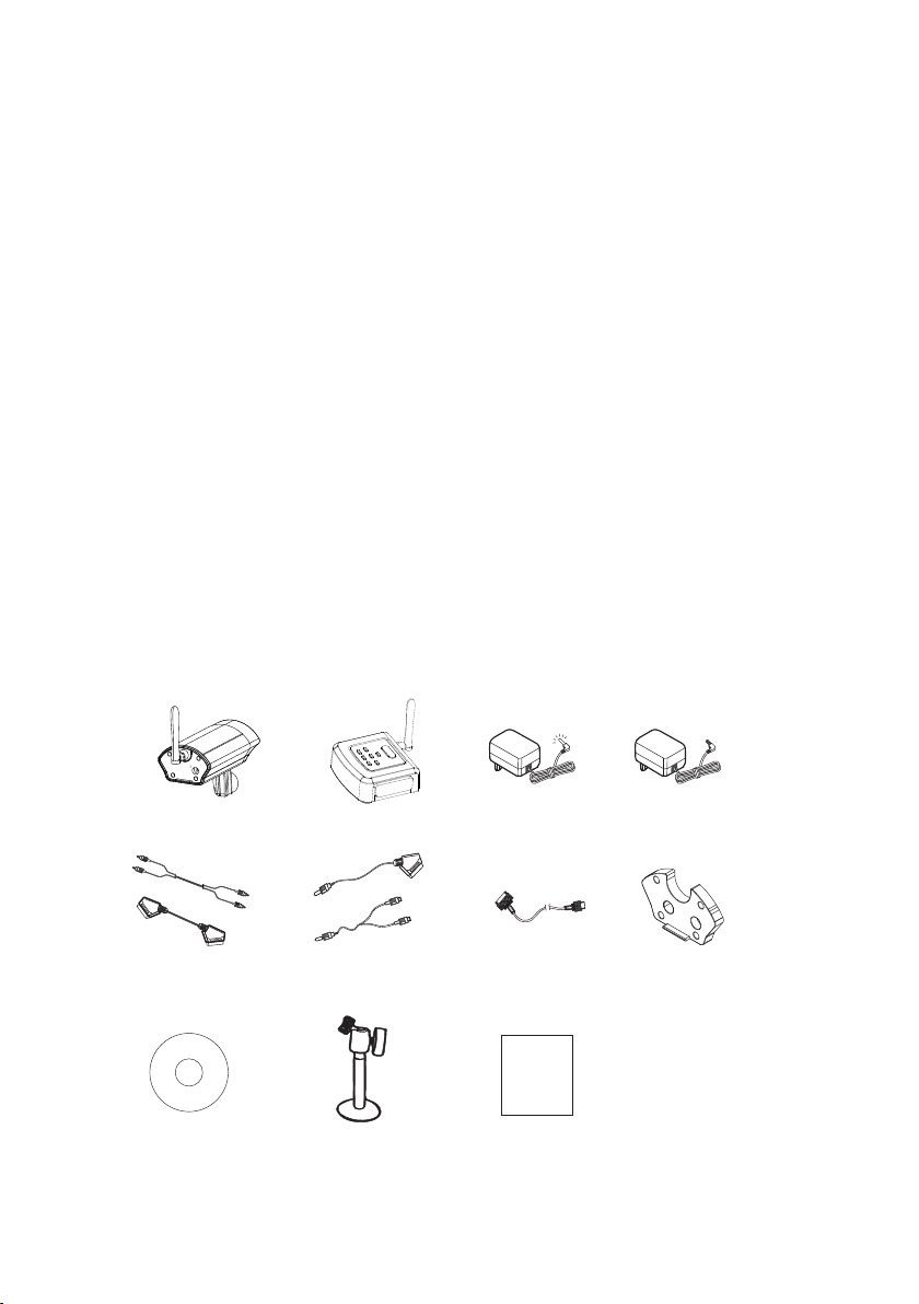
PACKAGE CONTENTSPACKAGE CONTENTS
Check all of the components shown as below
are included in box before using.
1. Wireless Camera
2. Receiver
3. 9V Power Adaptor (for Camera)
......................... .. .. .. .. .. .. .. .. ............................... .. .. .
........................... .. .. .. .. .. .. .. ...............
4. 5V Power Adaptor (for Receiver)
5. RCA/ Scart Cable
6. AV Cable
7. USB Cable
......................... .. .. .. .. .. .. .. .. ............................... .. ..
......................... .. .. .. .. .. .. .. .. ...............................
8. Waterproof of Cover
Software CD
9.
Stand (for Camera)
10.
11. Manual
Tra ns mi tt er
........................... .. .. .. .. .. .. .. ...........................
........................... .. .. .. .. .. .. .. ............................... .. .. ..
Receiver
........................... .. .. .. .. .. .. .. ...............
........................... .. .. .. .. .. .. .. ..........
......................... .. .. .. .. .. .. .. .. ............
DC 9V
(Camera)
......................
..................
DC 5V
(Receiver)
x1
x1
x1
x1
x1
x1
x1
x1
x1
x1
x1
(or Scart cable)
Software CD
A/V CableRCA Cable
Stand
(Camera)
USB Cable Wat er pr oo f of C ov er
Users Manual
01
Page 4
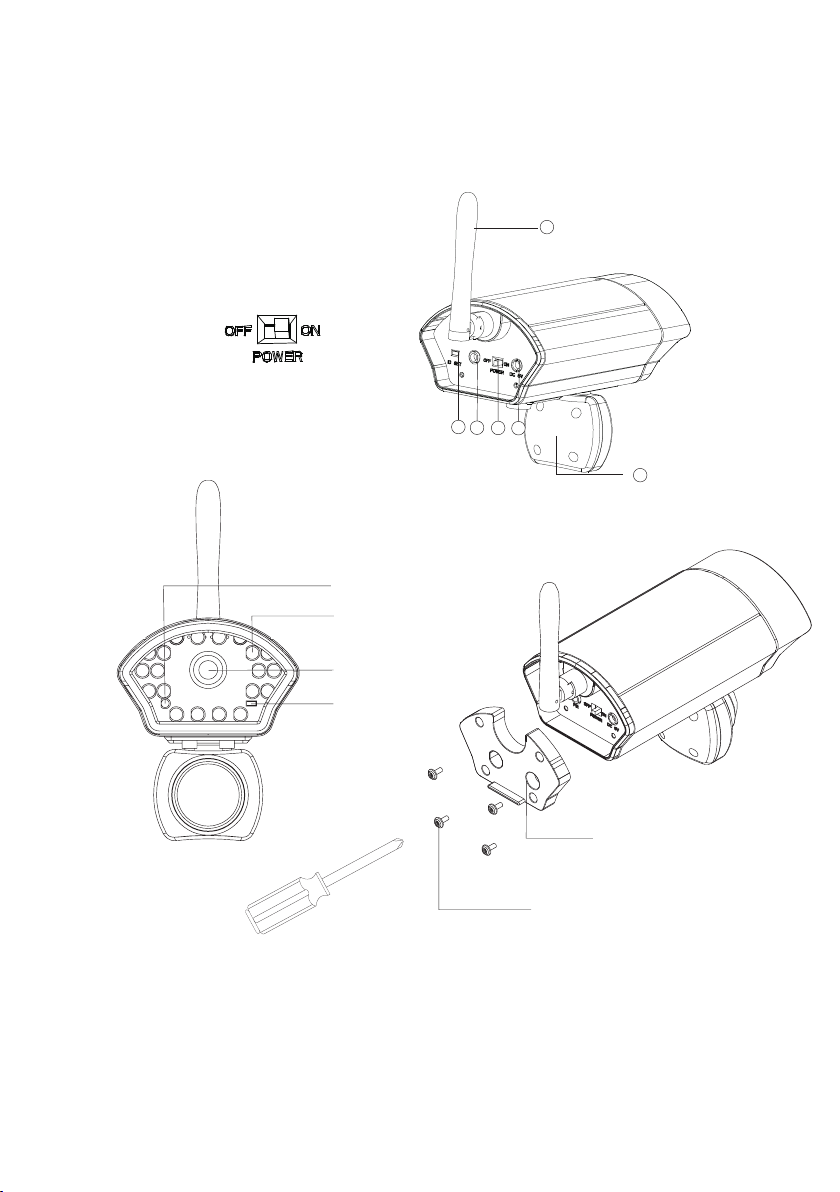
FUNCTION INTRODUCEFUNCTION INTRODUCE
Wireless Camera
1. ID SET
2. PIR Jack
3. Power Switch
4. DC Jack
5. Antenna
6. PIR
Power Light
LED Light
Camera Lens
Light Sensor
5
1
2
3
4
6
Wat er pr oo f of C ov er
Screw
Notice: Please put th e waterproof of cover to back of c amera with
screws after finish ing all setting.
02
Page 5
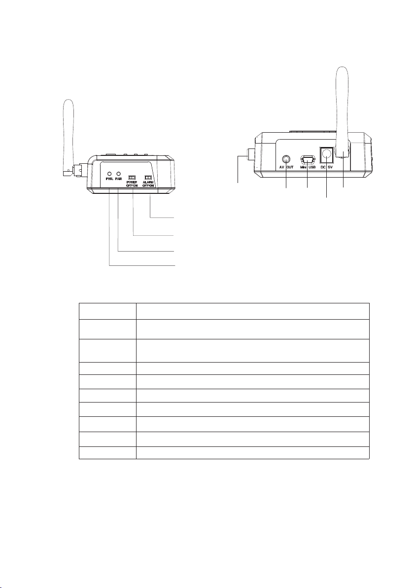
FUNCTION INTRODUCEFUNCTION INTRODUCE
Receiver (RCA port)
Item
Buzzer ON/OFF
Alarm Setting
Pairing Light
Power Light
AV out put
USB Port
DC Jack
Antenna
RCA Output
RCA output
AV out
USB
Antenna
DC Jack
Buzzer ON/O FF
Alarm setti ng(OFF / ON)
Pairing Lig ht
Power Light
Define
Turn OFF the Buzzer, and it won’t sound after detonating
Turn ON the Buzzer, and it will sound after detonating
OFF: Turn off t he alar m system, it will haven’t the detonating function.
ON: Camera always sen d the sig nal to re ceive r.
It sparkles when the re ceive r are pai ring wi th the ca mera
It lights when the powe r on.
Connect to monitor or D VR
Connect to computer
Connect to Power adaptor
Receive the Camera si gnal
Connect the televis ion
03
Page 6
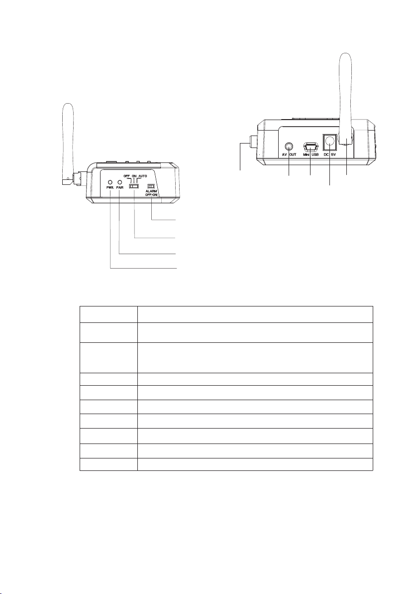
FUNCTION INTRODUCEFUNCTION INTRODUCE
Receiver (Scart port)
Item
Buzzer ON/OFF
Alarm Setting
Pairing Light
Power Light
AV out put
USB Port
DC Jack
Antenna
RCA Output
Scart output
AV out
USB
Antenna
DC Jack
Buzzer ON/O FF
Alarm setti ng(OFF/ON/AUTO)
Pairing Lig ht
Power Light
Define
Turn OFF the Buzzer, and it won’t sound after triggering
Turn ON the Buzzer, and it will sound after triggeri ng
OFF: Turn off t he alar m system, it will haven’t the detonating function.
AUTO: Stan d by mode . Camer a signa l was off unless i t was tri ggere d.
ON: Camera always sen d the sig nal to re ceive r.
It sparkles when the re ceive r are pai ring wi th the ca mera
It lights when the powe r on.
Connect to monitor or D VR
Connect to computer
Connect to Power adaptor
Receive the Camera si gnal
Connect the televis ion
04
Page 7

FUNCTION INTRODUCEFUNCTION INTRODUCE
Receiver(Button Define)
Hot Key
1
Zoo m In /Ou t
Notice: The Butto n do n’ t wo rk (e xc ep t “H ot K ey”) when connecting PC
Item
Hot Key
Menu/Next
(Camera 1)
Up
Right
(Camera 2)
Down
(Camera 3)
Left
(Camera 4)
Quad View / Pa ir
Cut the buzzer immediately. wh en t he R ec ei ve r al arm,
press it and sound stopped
Press “Menu” to enter t he sett ing sys tem, an d selec t funct ion you w ant
to set; press again the s ystem w ill ent er the ne xt page , press t wice
and then leave the sett ing sys tem.
Press “Up” to choose up ward fr om the se tting i tem.
Press “Right” to set ri ghtwa rd from t he item y ou choo se .
Press “Down” to set dow nard fr om the it em you ch oose.
Press “Left” to choos e leftw ard fro m the set ting it em.
Zoom In /Out. Enlarge t wo time s the cam era vid eo or bac k to norm al size .
In Menu mode: select “C am Pair ” funct ion, an d press “ pair” b utton o n
Receiver to make a ID mat ch with c amera .
In TV m ode: pr ess “Qu ad View” button then start to sh ow quad v iew, pre ss
again and back to the pre vious c amera .
4
Men u/Nex t
3
Define
2
Qua d View/ Pair
Notice:
The UP、Right、 Left、D ow n bu tt on c an b e th e hotkey for switching to one of four
camera immediately.
05
Page 8

FUNCTION INTRODUCEFUNCTION INTRODUCE
Menu
Press Menu button:
First page (press “Menu” for once)
Item
NTSC/PAL
Language
Cam Pair
Scan Time
Image Quality
Zoom In/Zoom Out
FREQ
English
1 2 3 4
OFF
5sec
10sec
15sec
QVGA
Normal
VGA
Enlarge two times the camera video or back to nor ma l si ze .
In “Zoom In” mode. the Vi de o qu al it y is “ QV GA ” on ly.
50/60 Hz
Default
PAL
English
To adjust the frequency o f camer a side.
Second pa ge(press “Menu” again)
Camera 1
Camera 2
Camera 3
Camera 4
Reset
ON/OFF
Tur n on o r off the camera signal.
Reset all setting.
Define
Setting NTSC or PAL by hand
Select one of four channels, and
then press the “ID SET” button of
camera and receiver to pair with
each other(in 60 seconds).
Glance every camera that has
paired with receiver already.
And it can select the time interval
of glance or off.
Select the video quality to show
on the monitor
Press “Menu” for third time and back to c amera video.
06
Page 9

SYSTEM INSTALLATIONSYATEM INSTALLATION
Camera Install
Set the Camera:
Plug the 9V DC adaptor to Camera and switch to powe r
on.
Receiver Install
Set the Receiver:
1. Plug the 5V DC adaptor to Receiver and switch to p ow er o n.
2. Two ways to set up rece iv er ;
a) Connect to Monitor and DVR at the same time
( )
DC 9V
power a dap tor
Monitor
DVR
b) or Connect to Computer
NO TEBOO K
PC
Notice:
(1) TV mode and PC mode c an n ot c on ne ct t he r ec ei ve r at the same time.
(2) Receiver connect to PC don’t need to plug the p ow er a da pt or.
RCA cable(wh it e to wh ite , yello w to ye llo w)
AV cable
USB cable
07
DC 5V
power a dap tor
Page 10

SYSTEM INSTALLATIONSYATEM INSTALLATION
Software Install (connect to computer)
1. Put the compact disk to CD-ROM drive of PC
2. Install the software of A alarm viewer
Step 1
Press the A+ alarm viewer twice,
than start to install
Step 3
Please click the “Next”
+
Step 2
Please click the “Next”
Step 4
Then press the “Finish” to
complete installation
08
Page 11

SYSTEM INSTALLATIONSYATEM INSTALLATION
Software Function
Item
File
Preview
Setup
Option
Auto Record : the system will
record the camera video
automatically after triggering
Save as
Exit
Start Preview
Stop Preview
Device Setup
Video Property
Define
Move the camera video file or photos to another p at h( 09 -1 )
Close the software
Start to preview
Stop previewing
Select one of four channel, then press ID SET on ca me ra
in 60 seconds, the screen will show the camera vi de o if
the pairing is successful.(09-2)
Setting the video property(09-3,09-4)
09-1
09-1
09-2
09-3
09-4
09
Page 12

SYSTEM INSTALLATIONSYATEM INSTALLATION
Software Function
E
D
C
A
B
J
H
I
K
F
G
10-1
(A) Move the came ra v id eo f il e or p ho to s to a no th er path
(B) Press it and Auto Reco rd the ca mera vi deo for 1 7~19 se conds e ach fil e after triggering. (Avi for mat)
(The video signal wil l be save d to C:/ vi deo, un less yo u chang e the sto rage path. )
(C) Take the pic ture (J pg form at)
(The photo will be save d to C:/ vi deo, un less yo u chang e the sto rage pa th )
(D) Record the camera v ideo. Each vi deo fil e can rec ord 5 min utes at m ost. (Avi form at)
(The video signal wil l be save d to C:/ vi deo , unl ess you c hange t he stor age path. )
(E) Choose the camera c hanne l or quad m ode.
(F) Turn on the buz zer on co mpute r.
(G) Turn off th e buzze r on computer.
(H) Show the wireless s ignal .
(I) Show four cameras , and it tu rns to re d color a fter de tonat ing.( 10-1) .
(J) Preview all video f iles an d photo s in this t ime sof tware o penin g. click one of them twice will play the file.
(K) Show the real time of c amera v ideo.
10
Page 13

OPERATIONOPERATION
Work with TV
Step 1:
Power on the receiver and camera
Step 2:
Complete the pairing
Step 3:
Receiver connects to TV b y RC A or Sc ar t ca bl e (P 7)
Step 4:
Press the TV/AV bu tt on on controller of TV, then switch to camera channel.
You ca n se le ct a ny s et ti ng on receiver when the TV moni to r is s wi tc he d to c am er a.
Step 5:
Press the hot key on receiver to stop the buzzer af te r de to na ti ng .
(The buzzer function will start to work again a ft er 2 m in ut es . )
Work with Computer
Step 1:
Install the software to computer (P8)
Step 2:
Power on the receiver and connect to computer b y US B ca bl e( P7 )
Step 3:
Power on the camera
Step 4:
Open the A+ alarm
Step 5:
Then start to work(P8)
Step 6:
The buzzer on receiver and computer are both al ar m.
(The buzzer function on receiver side will st ar t to w or k ag ai n af te r 2 mi nu tes. )
And press the buzzer off on s of tw ar e to s to p th e bu zzer after detonating.
Notice:
Please refer to the trouble shooting when the A+ a la rm s of tw ar e is s ho we d
“ Can not connect to device” .
11
Page 14

TROUBLE SHOOTINGTROUBLE SHOOTING
Buzzer alarm doesn’t work?
1. Make sure the receiver and camera are power on .
2. Make sure the PIR cable is plugged into PIR port
3. Check the alarm setting of receiver is in “STB ” or “ ON ”.
4. Check the receiver is paired with camera alr ea dy.
5. Check the receiver is switched to Buzzer on.
Buzzer alarm can’t turn it off ?
1. Buzzer keep alarming If the camera is still tr ig ge ri ng .
Receive r Doesn’t work with comput er?
1. Make sure the receiver and camera are power on .
2. Check the alarm setting of receiver is in “STB ” or “ ON ”.
3. Check the receiver is paired with camera alr ea dy.
4. Check the USB cable is plugged to the computer.
(or unplug other device, only plug the receiv er a nd t ry a ga in . so me ti me s
USB cable don’t work cause the computer USB por t po we r wa s sh ar ed t o
another device)
5. Make sure the software has installed alrea dy.
Receive r connect to TV don’t work?
1. Make sure the receiver、 camera and TV a re p ow er o n.
2. Check the alarm setting of receiver is in “STB ” or “ ON ”.
3. Check the receiver is paired with camera alr ea dy.
4. Check the RCA cable is plugged to the TV al re ad y. and press the
A/V button on controller to switch to camera vi de o.
Camera do esn’t work?
1. Make sure the camera are power on.
2. Make sure the PIR cable is plugged into PIR port
3. Check the power switch is “ON”.
TV monitor doesn ’t show camera vide o?
1. Make sure the receiver and camera are power on .
2. Make sure the PIR cable is plugged into PIR port
3. Check the alarm setting of receiver is in “STB ” or “ ON ”.
4. Check the receiver is paired with camera alr ea dy.
12
Page 15

TROUBLE SHOOTINGTROUBLE SHOOTING
The software shows “can not connect t o device”?
1. Make sure the receiver are power on.
2. Make sure the USB cable is plugged.
3. Check the alarm setting of receiver is in “STB ” or “ ON ”.
4. Check the power light is opened.
Why do the PIR trigg ered without trig gering at times?
The PIR is a kind of sensor, so it is very easy triggere d by i rr es is ti bl e fa ct or s.
ex:wind、humidity、rainy day.
The PIR do not trigg er at times?
The distance of workable of PIR is 3~5M, so it won’ t be t ri gg er ed o ut o f ra ng e.
Why can’t the receiver and camera pai r with ?
1. Make sure the alarm switch is “on” or “Auto”
2. Make the receiver and camera are power on
3. Receiver(work to TV) : me nu -> ca m pa ir -> s el ect one of four channels->
press “pair” button on receiver-> press “ID S et ” on C am er a in 6 0 se co nd s
4. Receiver(work to PC):open software-> Se tu p- >d ev ic e se tu p- >
select one of four channels ->press “ID Set” on C am er a in 6 0 se co nd s
5. Change another channel and try again.
6. Move your receiver and camera slowly to find a b es t re ce pt io n po si ti on f or
your security product
7. Check if there is any interference source ne ar r ec ei ve r or c am er a, s uc h as
microwave oven.
13
Home Surv eillance System
Digital Wireless Camera & Receiver
Page 16

Home Surv eillance System
Digital Wireless Camera & Receiver
Page 17

Federal Communication Commission Interference Statement
This equipment has been tested and found to comply with the limits for a Class B
digital device, pursuant to Part 15 of the FCC Rules. These limits are designed to
provide reasonable protection against harmful interference in a residential installation.
This equipment generates, uses and can radiate radio frequency energy and, if not
installed and used in accordance with the instructions, may cause harmful interference
to radio communications. However, there is no guarantee that interference will not
occur in a particular installation. If this equipment does cause harmful interference to
radio or television reception, which can be determined by turning the equipment off
and on, the user is encouraged to try to correct the interference by one of the
following measures:
. Reorient or relocate the receiving antenna.
. Increase the separation between the equipment and receiver.
. Connect the equipment into an outlet on a circuit different from that to which the
receiver is connected.
. Consult the dealer or an experienced radio/TV technician for help.
FCC Caution: To assure continued compliance, any changes or modifications not
expressly approved by the party responsible for compliance could void the user's
authority to operate this equipment. (Example - use only shielded interface cables
when connecting to computer or peripheral devices).
FCC Radiation Exposure Statement
This equipment complies with FCC RF radiation exposure limits set forth for an
uncontrolled environment. This equipment should be installed and operated with a
minimum distance of 20 centimeters between the radiator and your body.
This transmitter must not be co-located or operating in conjunction with any other
antenna or transmitter.
The antennas used for this transmitter must be installed to provide a separation
distance of at least 20 cm from all persons and must not be co-located or operating in
conjunction with any other antenna or transmitter.
This device complies with Part 15 of the FCC Rules. Operation is subject to the
following two conditions:
(1) This device may not cause harmful interference, and (2) This device must accept
any interference received, including interference that may cause undesired operation.
 Loading...