

Page 1
Micro Tracker user guide
Micro Tracker
Firmware V1.6
ABEEWAY SAS
contact@abeeway.com
www.abeeway.com
Page 2

Micro Tracker User Guide FW1.6 V1.1
Page 2 of 17
11 October 2018
Company Confidential – restricted distribution
Table of contents
1 Introduction ............................................................................................................................ 3
1.1 General Description .......................................................................................................... 3
1.2 Applications ...................................................................................................................... 3
2 Features .................................................................................................................................. 3
3 Installation .............................................................................................................................. 4
3.1 Getting started .................................................................................................................. 4
3.2 Fixation ............................................................................................................................. 4
4 Functioning ............................................................................................................................. 5
4.1 Main operating modes ...................................................................................................... 5
4.2 Side operations ................................................................................................................. 6
4.3 User interface ................................................................................................................... 6
4.4 Geolocation strategies ...................................................................................................... 8
5 Uplink messages ...................................................................................................................... 9
6 Remote configuration using ADA ........................................................................................... 10
6.1 Operating Mode Configuration ....................................................................................... 10
6.2 Position on demand ........................................................................................................ 10
6.3 Parameters configuration ................................................................................................ 10
7 Downlink messages ............................................................................................................... 11
7.1 Ack Token ........................................................................................................................ 11
7.2 Mode Configuration ........................................................................................................ 12
7.3 Position on demand ........................................................................................................ 12
7.4 Parameters configuration ................................................................................................ 12
8 Specifications ........................................................................................................................ 15
8.1 Physical configuration ..................................................................................................... 15
8.2 Estimated lifetime ........................................................................................................... 15
8.3 Data communication support .......................................................................................... 15
8.4 Position accuracy ............................................................................................................ 16
8.5 Power management ........................................................................................................ 16
9 Products References .............................................................................................................. 16
Page 3
Micro Tracker User Guide FW1.6 V1.1
Page 3 of 17
11 October 2018
Company Confidential – restricted distribution
1 Introduction
1.1 General Description
The Abeeway Micro Tracker is a multi-mode tracker combining GPS/Low power GPS, Wi-Fi, LoRa,
BLE radios with embedded sensors to support accurate outdoor and indoor geolocation. A button,
a buzzer and 3 LEDs are available to interface with the user. The Micro Tracker, with its small size and
long battery lifetime, is the ideal product for many tracking applications.
1.2 Applications
➢ Asset tracking at fixed frequency updates or on demand.
➢ Personal tracking with help button.
➢ Safety monitoring for isolated workers inside facilities or in outdoor.
➢ Anti-theft; Notification and location when device is moving.
➢ Geofencing applications.
2 Features
➢ Multiple operating modes
• Motion tracking: Get the tracker position at a given cycle when motion is detected.
• Permanent tracking: Get permanently a position of the tracker.
• Start/End motion tracking: Get position messages during motion start and end
events.
• Activity tracking: Monitor activity rate with embedded sensors.
• OFF: device stopped
➢ Position on demand: Receive the tracker position only when needed (very low power
operating mode).
➢ Used geolocation technologies
• GPS: Precise outdoor position.
• Low power GPS: get quick position outdoors and daylight indoor conditions.
• WI-FI: Position indoors and urban area.
➢ Buzzer and LEDs
➢ Temperature monitoring
➢ Embedded antennas
➢ LoRa™ Class A radio
➢ Water-spray resistant enclosure (IP64)
Commenté [AD1]: Need to be aligned with dataheet
Page 4
Micro Tracker User Guide FW1.6 V1.1
Page 4 of 17
11 October 2018
Company Confidential – restricted distribution
3 Installation
3.1 Getting started
➢ Charge your device using a micro USB cable. While charging the white led is ON. When the
battery is fully charged the white LED goes OFF.
➢ A long press is needed to turn ON the device (starting in motion tracking mode in standard
configuration).
➢ Your network can use two activation modes:
o OTAA (Over The Air Activation) that requires the following keys to make the join: DEVEUI,
APPEUI and APPKEY for each device. (the most used)
o ABP (Activation by personalization) that requires the following keys to make the join:
DEVEUI, DEVADDR and NWKSKEY for each device
➢ Depending on your operator, some actions need to be done to activate the transfer of the
data through Abeeway servers. Please refer to your vendor for more information.
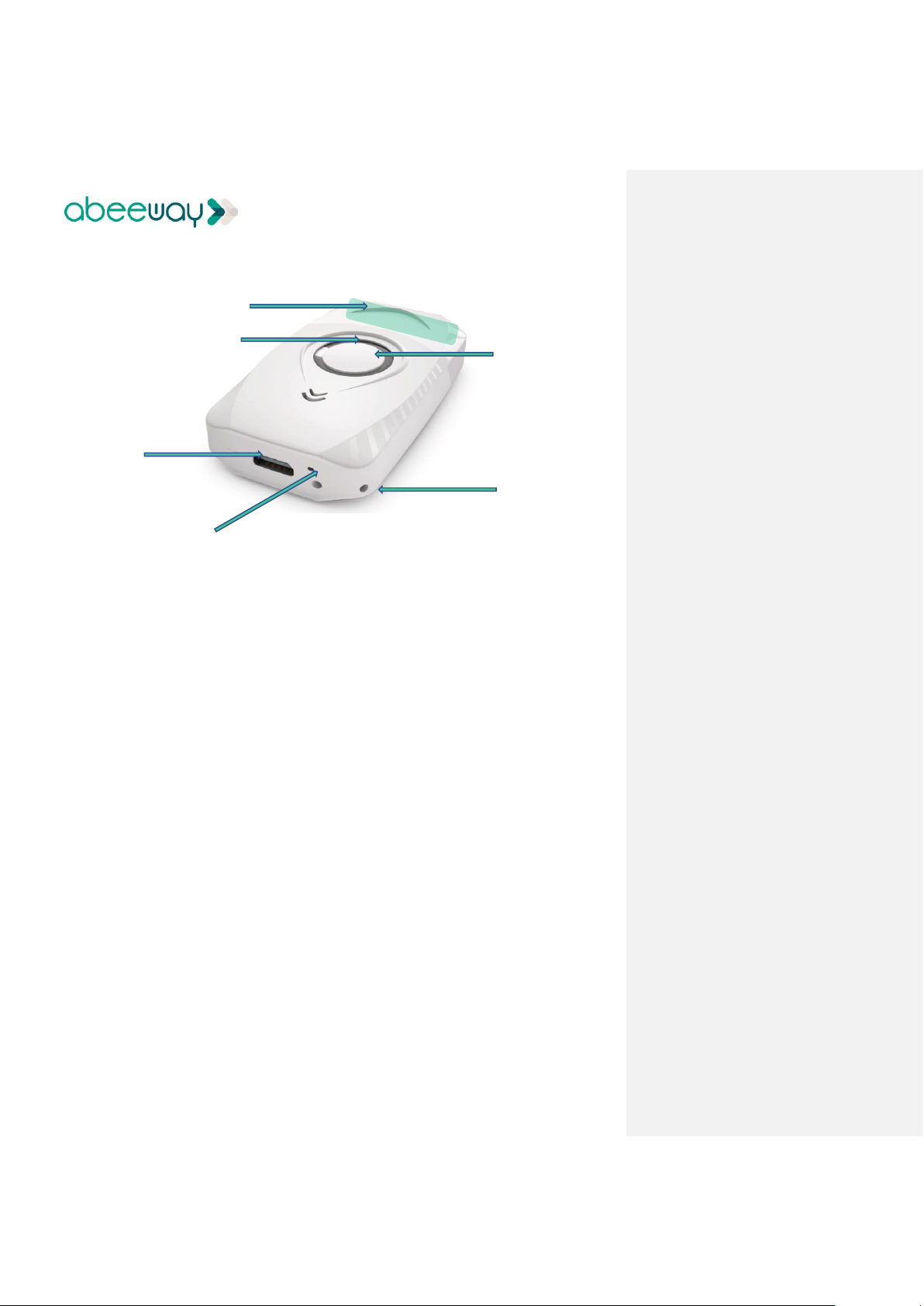
3.2 Fixation
The device can be attached with the provided lanyard or placed in bag, or inside an asset.
Note: the environment and orientation of the tracker can influence the radio performance. For
optimum results keep the zone around the antenna area clear from any conducting material or
magnetic field.
Blue LED
Button
Lanyard
White Charge LED
Micro USB
Antennas area
Page 5

Micro Tracker User Guide FW1.6 V1.1
Page 5 of 17
11 October 2018
Company Confidential – restricted distribution
4 Functioning
4.1 Main operating modes
This section describes the different operational modes supported by the trackers.
OFF mode: The tracker is in deep low power mode. No uplinks are sent in this mode. A long button
press is required to wake it up. Three possibilities to set the tracker in OFF mode:
➢ User action (long button press)
➢ Low battery
➢ Downlink request
Standby mode: The tracker is sending periodically short LoRa messages, called heartbeat at the
chosen period (lora_period). Device position can be obtained in this mode by using the side
operations features (see next section).
Motion tracking mode: The tracker provides positions when the device is moving. The reporting is
done at the chosen period (ul_period). The positions are acquired based on the geoloc_sensor
geolocation technology. If the device is not moving, heartbeat messages are sent regularly at the
lora_period frequency. Additional positions can be obtained by using the on-demand side
operations features.
Note: Whatever the chosen geolocation policy, the first position is always established via WI-FIWiFi sent immediately after the beginning of the motion.
Permanent tracking mode: The device reports its positions at ul_period frequency regardless the
motion. It uses the geoloc_sensor geolocation technology. Heartbeat messages are sent if there are
no uplink message during lora_period seconds.
Motion Start/End tracking mode: In this mode, position messages are sent twice, at the start and
at the end of a motion (one Wi-Fi and one using the geoloc_sensor geolocation technology). The
end of the motion is detected when there is no movement detection for a period of 120 seconds.
Heartbeat messages are sent if there are no uplink message during lora_period seconds. Additional
positions can be obtained by using the on-demand side operation feature.
Activity mode: This mode sends activity reports instead of positions. The tracker focuses on
detecting movements. Each shake detection increases a counter (after applying an integration
period). The value of the counter is reported up the LoRa link at the ul_period frequency. Heartbeat
messages are sent if there are no uplink messages during lora_period seconds. Additional positions
can be obtained by using the on-demand side operations features.
Note: The accuracy of the different frequencies is not guaranteed as extra delay may be introduced
by the LoRa network duty cycle.
Page 6
Micro Tracker User Guide FW1.6 V1.1
Page 6 of 17
11 October 2018
Company Confidential – restricted distribution
4.2 Side operations
Whatever the mode, optional messages can be sent according to the configuration. The side
operations can be:
Periodic position message: The device sends periodically its position at periodic_pos_period
frequency. Usually, this reporting frequency is very long. The position is sent three times (six if the
device is moving).
Position on Demand: Position requests are done via LORA downlink message. The device answers
with its current position.
Alert position: A double press on the button generates a LORA uplink message containing the
position.
Notes:
➢ The geolocation strategy used in these cases is geoloc_method one.
➢ The side operations can be cumulated.
4.3 User interface
4.3.1 Button management
Sequence
Action
Output
One short press
Show current mode and state
Led state pattern (see next
section)
Two short presses
Trigger an alert position
Other Led pattern (see next
section)
Any press when battery low
(short or long press)
Go to OFF mode
Buzzer melody
other Led pattern (see next
section)
One long press when device
OFF and good battery
Wake up
Other Led pattern (see next
section) only for the first wake
up after reset
One very long press (5 s) when
device ON.
Go to the OFF mode
Buzzer melody
Button down when device is
ON
Blue LED ON
Page 7

Micro Tracker User Guide FW1.6 V1.1
Page 7 of 17
11 October 2018
Company Confidential – restricted distribution
4.3.2 Blue LEDs mode and state patterns
This interface output is triggered by a single short button press. It generates two main sequences
The two sequences are consecutives. The first one indicates the mode, and, is followed by the
state of the tracker. The LED behavior are provided below.
Show current mode
➢ Mode Standby: No blink.
➢ Mode Motion Track: One long blink.
➢ Mode Permanent Track: Two long blinks.
➢ Mode Motion Start/End Track: Three long blinks.
➢ Mode Activity: Four long blinks.
Show current state
➢ State Idle: No blink.
➢ State Tracking: Two fast blinks.
4.3.3 Other blue LEDs patterns
Three fast blinks
Go to the OFF mode (Low battery)
Three slow blinks
Device starting for the first time
Long fast blink of blue LED
LORA join operation in progress
Fast blink of blue LED after two button
clicks
Device acknowledges the alert position
4.3.4 Buzzer melodies
There are three different melodies:
Melody
Meaning
Major rising scale
Device is starting
Major falling scale
Device is going to OFF mode
Low battery
Low battery detected
Page 8

Micro Tracker User Guide FW1.6 V1.1
Page 8 of 17
11 October 2018
Company Confidential – restricted distribution
4.4 Geolocation strategies
4.4.1 Main operating modes
The following geolocation policies (geoloc_sensor parameter) are used when the operating mode
is either motion-tracking, permanent-tracking, or start/end tracking.
➢ WI-FI only → Only WI-FI scans are used for position determination.
➢ GPS only →Only the GPS is used for position determination.
➢ LP-GPS only→ GPS and LP-GPS are used for position determination.
➢ Multimode (WI-FI + AGPS + GPS)→ Alternate WI-FI, LP-GPS and GPS technologies on failure,
with timeout.
➢ Wi-Fi-GPS only → WI-FI then GPS if Wi-Fi fails in one geolocation cycle.
➢ Wi-Fi-LPGPS only → Wi-Fi then LP-GPS if Wi-Fi fails in one geolocation cycle.
➢ Wi-Fi-LPGPS/ Wi-Fi-GPS → Wi-Fi-LPGPS first, then Wi-Fi-GPS if Wi-Fi-LPGPS fails until
timeout, then back to Wi-Fi-LGPS.
Note: The first position is always a Wi-Fi one whatever the chosen geolocation strategy.
4.4.2 Side operations
The following geolocation policies (geoloc_method parameter) are used for periodic-reporting or
on-demand actions.
➢ Wi-Fi only → Only Wi-Fi scans are used for position determination.
➢ GPS only →Only the GPS is used for position determination.
➢ LP-GPS only→ GPS and LP-GPS are used for position determination.
➢ Wi-Fi-GPS only → Wi-Fi then GPS if Wi-Fi fails in one geolocation cycle.
➢ Wi-Fi-LPGPS only → Wi-Fi then LP-GPS if Wi-Fi fails in one geolocation cycle.
Page 9

Micro Tracker User Guide FW1.6 V1.1
Page 9 of 17
11 October 2018
Company Confidential – restricted distribution
5 Uplink messages
Type of message
Content
Heartbeat message
Notify the server the tracker is operational and under LoRa coverage
Position message
GPS, low power GPS or Wi-Fi position data
Energy status message
Used by the server to estimate the battery level. Contain information
related to the power consumption
Activity Status
message
Reports the activity counter. Used only by the activity tracking operating
mode
Debug message
Internal used only
Frame pending
When additional downlink messages are available on gateway, this uplink
message is sent to trigger the sending (and speed up the configuration of
the tracker)
OFF message
Notify the move to the OFF state
Page 10

Micro Tracker User Guide FW1.6 V1.1
Page 10 of 17
11 October 2018
Company Confidential – restricted distribution
6 Remote configuration using ADA
All following parameters are configurable in Abeeway Data Analyzer (ADA) application
6.1 Operating Mode Configuration
All modes can be set using ADA application:
➢ Standby
➢ Motion tracking
➢ Permanent tracking
➢ Motion start/end tracking
➢ Activity tracking
➢ OFF
6.2 Position on demand
Position of the tracker can be requested.
6.3 Parameters configuration
Following parameters are configurable:
➢ Parameters used in the main operating modes:
✓ LoRa Heartbeat: period of Lora Heartbeat messages
✓ Position report: period of LoRa position messages
✓ Geolocation methodology (geoloc sensor)
➢ Parameters used in side operating modes:
✓ Periodic position: activation, and period of LoRa position messages
✓ Geolocation methodology (geoloc method)
Page 11

Micro Tracker User Guide FW1.6 V1.1
Page 11 of 17
11 October 2018
Company Confidential – restricted distribution
7 Downlink messages
These messages are sent from the server to the tracker through the LoRa network. They are used
to configure the tracker or request a position. Each message contains a header including:
➢ A message type
➢ An acknowledgement token
The remaining of the message depends on the message type. The tracker accepts three types of
downlink messages, listed in the following table:
Message type
ID
Description
POD
0x01
Position on demand
Set Mode
0x02
Change the tracker mode
Set Param
0x0B
Modify a parameter
Notes
1. Any unexpected message (unknown message type, bad length, ...) is discarded. However,
the ack token is updated even if the message is discarded (if the payload is at least 2 bytes
long).
2. The LoRa port to be used for downlink is 2.
7.1 Ack Token
It provides a way to indicate to the application that a given message has been received and
processed by the tracker.
The ack token is transmitted in every uplink message, and it is updated when the tracker receives a
LoRa message. This way, each time the server receives a LoRa uplink, it knows whether the previous
message has been received.
The ack token is four bits long. Its value ranges from 0 to 15(0x0F).
Notes
1. The ack token value should be updated for each downlink to be used by the application.
2. It’s up to the application to process or not the ack tokens.
3. It’s up to the application to manage the confirmations. It can either wait for the matching
ack token in the uplink message before sending another downlink or send multiple downlink
and later waits for the acks.
Page 12

Micro Tracker User Guide FW1.6 V1.1
Page 12 of 17
11 October 2018
Company Confidential – restricted distribution
7.2 Mode Configuration
The operating mode can be remotely configured with a downlink LoRa message built as follow:
Byte 0
Byte 1
Byte 2
0x02
ACK
Mode
ACK: Ack token. Refer to the associated section.
Mode: operating modes. Acceptable values are:
➢ 0- Standby
➢ 1- Motion tracking
➢ 2- Permanent tracking
➢ 3- Motion start/end tracking
➢ 4- Activity tracking
➢ 5- OFF
Example:
Changing the operating mode to “motion tracking” (01) with an ack token of 3: 0x020301.
7.3 Position on demand
Whatever the state, a position can be requested from the tracker by the message:
Byte 0
Byte 1
0x01
ACK
Example:
Position on demand message with ack token of 2: 0x0102.
7.4 Parameters configuration
Any parameter can be remotely modified with a downlink LoRa message.
Such messages are built according to the following format:
Byte 0
Byte 1
Byte 2
Byte 3-6
0x0B
ACK
Parameter ID
New value [31-00]
Page 13

Micro Tracker User Guide FW1.6 V1.1
Page 13 of 17
11 October 2018
Company Confidential – restricted distribution
The parameters identifier and the values are given in the following table
Parameter
ID
Unit
Range
Description
Position period
ul_period
0x00
second
60 - 86400
Period of position or activity messages in
motion tracking, start end tracking,
activity mode or permanent operating
mode
heartbeat period
lora_period
0x01
second
300 - 86400
Period of heartbeat messages (sent only
in idle state)
Periodic position
report period *
periodic_pos_period
0x03
second
0,
900 - 604800
Period of the periodic position report.
When 0, no periodic position report is
transmitted.
Geolocation sensor
profile
Geoloc_sensor
0x05
none
0 - 9
Geolocation policy used in motion, start
end or permanent tracking operating
mode
0- Wi-Fi only
1- GPS only
2- LP-GPS (AGPS/GPS)
3- Reserved (do not use)
4- Reserved (do not use)
5- Multimode (Wi-Fi + LP-GPS + GPS) (with
reset to Wi-Fi on timeout)
6-Wi-Fi-GPS only (Wi-Fi then GPS if Wi-Fi
fails in one geolocation cycle)
7- Wi-Fi-LPGPS only (Wi-Fi then LP-GPS if
Wi-Fi fails in one geolocation cycle)
8- Reserved (do not use)
9- Wi-Fi-LPGPS first, the Wi-Fi-GPS until
timeout, then back to Wi-Fi-LGPS
Oneshot geolocation
method
Geoloc_method
0x06
none
0-4
Geolocation policy used for periodic or on
demand positions:
0- WI-FI
1- GPS
2- XGPS (Low power GPS/GPS)
3- Wi-Fi-GPS only (Wi-Fi then GPS if Wi-Fi
fails in one geolocation cycle)
4- Wi-Fi-LPGPS only (Wi-Fi then LP-GPS if
Wi-Fi fails in one geolocation cycle)
Page 14

Micro Tracker User Guide FW1.6 V1.1
Page 14 of 17
11 October 2018
Company Confidential – restricted distribution
Example:
To modify the heartbeat period to 1 hour, the command 0x0B020100000E10 should be sent.
Description:
➢ (0x0B) : set the parameter.
➢ (0x02) : with an ack token of 2
➢ (0x01) : heartbeat message period.
➢ (0x 00 00 0E 10) : to a value of 3600s = 1 hour.
It is possible to modify two parameters in the same message by using the following format:
Parameter 1
Parameter 2
Byte 0
Byte 1
Byte 2
Byte 3-6
Byte 2
Byte 3-6
0x0B
ACK
ID
New value1 [31-00]
ID
New value2 [31-00]
Page 15

Micro Tracker User Guide FW1.6 V1.1
Page 15 of 17
11 October 2018
Company Confidential – restricted distribution
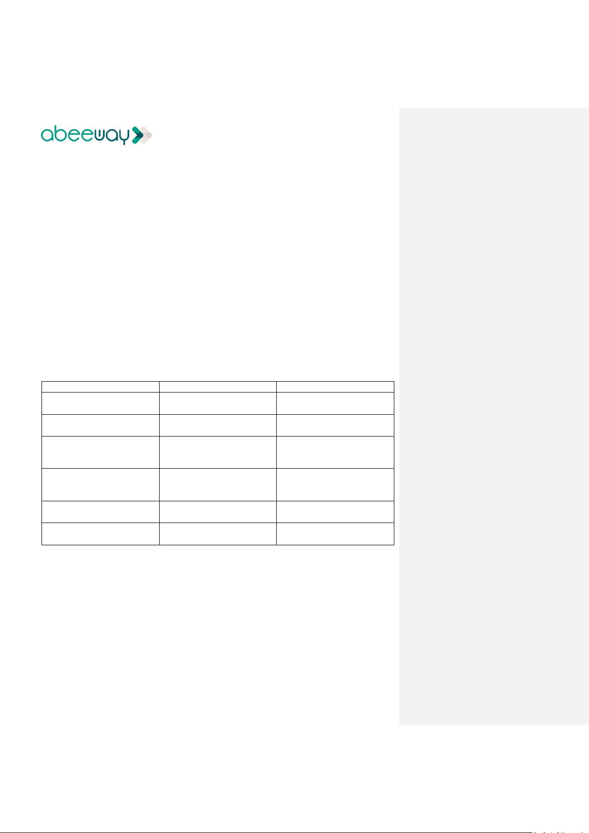
8 Specifications
8.1 Physical configuration
Size
59mm x 34 mm x13 mm (L x l x h)
Weight
21g
Waterproof capability
IP64
Operating temperature
0C to 45 C (Charge)
-10C to 55 C (Operation)
Storage temperature
10C to 30 C (recommended)
Humidity
5% to 95% non-condensing
Time storage max
6 months
Power supply
5v (using micro USB connector)
(1) In static, 5 satellites or more at -130 dBm
8.2 Estimated lifetime
Use Case
Battery Life (Approx.)
Standby mode
10 months at 20C
Movement detection (120 positions per day)
>10 days
(3)
(3) Using WIFI modes
8.3 Data communication support
LoRa™ Modem
Semtech transceiver SX1272
Protocol
LoRaWAN v1.0.2 Class A
Frequencies bands
EU 868MHz ISM band
US 902-928MHz
Configuration supported
OTA or ABP
RF power
14 dBm (EU)
16.5 dBm (max)
Min sensitivity of LoRa receiver
-130 dBm in SF10
WiFi Frequency band
2412 – 2472MHz
WiFi sniffer max emission
3 dBm
BLE sensitivity
-88 dBm
BLE RF output power
4 dBm max
BLE frequency band
2402 – 2480MHz
GNSS band
1559 – 1610MHz
Page 16

Micro Tracker User Guide FW1.6 V1.1
Page 16 of 17
11 October 2018
Company Confidential – restricted distribution
8.4 Position accuracy
GPS
Position Accuracy (50%-90%)
(2)
10 to 20 meters
Time to have a position
(2)
Cold start
50-210 seconds
Hot start
15 seconds
Acquisition sensitivity
-140 dBm
Low power
GPS
Position Accuracy (50%-90%)
(2)
15 - 30 meters
Time to have a position
(2)
10 - 30 seconds
Acquisition sensitivity
-160 dBm
Wi-Fi
Indoor Position accuracy
20 - 50 meters
Time to have a position
3 seconds
(2) In static, >5 satellites at -130 dBm
8.5 Power management
Rechargeable Battery
3.7V
0.45 Ah
Battery type
Lithium Polymer
Charger supply
5V from a standard micro USB charger
Power consumption
Stand-by: 0,01mA/h
GPS tracking in cold start
(1)
: 1,5mAh (per position)
Low power GPS tracking
(1)
: 0,3mAh (per position)
WiFi tracking: 0,1mAh (per position)
(1) In static, 6 satellites or more at -130 dBm
9 Instructions / Warnings
This device complies with Part 15 of the FCC Rules. Operation is subject to the following two
conditions: (1) this device may not cause harmful interference, and (2) this device must accept
any interference received, including interference that may cause undesired operation.
Any changes or modifications to this equipment not expressly approved by ABEEWAY may
cause, harmful interference and void the FCC authorization to operate this equipment.
This portable equipment with it’s antenna complies with FCC’s radiation exposure limits set
forth for an uncontrolled environment. To maintain compliance, follow the instructions below :
1. This transmitter must not be co-located or operating in conjunction with any other
antenna or transmitter.
2. Avoid direct contact to the antenna, or keep contact to a minimum while using this
equipment.
Page 17

Micro Tracker User Guide FW1.6 V1.1
Page 17 of 17
11 October 2018
Company Confidential – restricted distribution
This equipment has been tested and found to comply with the limits for a Class B digital device,
pursuant to part 15 of the FCC Rules. These limits are designed to provide reasonable
protection against harmful interference in a residential installation. This equipment generates,
uses and can radiate radio frequency energy and, if not installed and used in accordance with
the instructions, may cause harmful interference to radio communications. However, there is
no guarantee that interference will not occur in a particular installation. If this equipment does
cause harmful interference to radio or television reception, which can be determined by
turning the equipment off and on, the user is encouraged to try to correct the interference by
one or more of the following measures:
—Reorient or relocate the receiving antenna.
—Increase the separation between the equipment and receiver.
—Connect the equipment into an outlet on a circuit different from that to which the
receiver is connected.
—Consult the dealer or an experienced radio/TV technician for help
10 Products References
Product definition
SKU
MICRO TRACKER WHITE EU868 (option small packing box)
DEABE003-xxxEU
MICRO TRACKER WHITE US915 (option small packing box)
DEABE001-xxxUS
MICRO TRACKER WHITE US915 (option retail packing box)
DEABE004-xxxUS
Minor version updates are defined by suffix xxx
 Loading...