

Page 1

Thank you for purchasing the AB COASTER®.
Our customer service staff is ready to help
and to answer any questions.
Our phone number is: 908-879-2713
The Ab Coaster Company, 173 Route 206, P.O. Box 9
Chester, NJ 07930
Website: www.abcoasterclub.com
Email: [email protected]
Please call us if you have any questions.
Customer service staff can be reached
Monday to Friday from 9:00 AM to 5:00 PM Eastern Standard Time.
You can also send us an email, or visit our website
for additional customer service information.
Prior to calling or emailing,
please have the following information with you:
• Customer Name and Address
• Telephone Number
• Proof of Purchase
• Product Model Number
© 20 10 Th e Ab Coaste r Com pany. All Rights Reser ved.
U.S. Pat. Nos. 7,611 ,445, 7,585 ,263, 7,485 ,079, and O ther Patent s Pen ding.
U.S. Trade mark Regist ration Numb er 34 07362.
AbC_CTL_MAN_V2_100519
AbC_CTL_MAN_V2_100519.indd 1-2 5/28/10 2:31 PM
Page 2

SAFETY INSTRUCTIONS FOR ASSEMBLY AND USAGE
Safety comes first. Please read this instruction guide completely before assembling and
using the Ab Coaster®. Please keep this guide in a safe place and accessible to all staff.
• Make sure all bolts and screws are tight prior to each day’s use. Make sure machine
is working properly every day. WARNING: The safety level of this equipment can
be maintained only if it is examined regularly for damage and wear. Pay special
attention to the moving parts, including the bearings under the carriage and the pull
pin which secures the carriage, and to components which are susceptible to wear
such as the rear bumpers, the arm rests and seat.
• Periodic maintenance is required on all exercise equipment in order for it to remain
in good operating condition.
• Place and use the machine on a flat, level surface. Maintain at least 2 feet of free
space around machine for safe operation.
• Place all warnings and safety labels as provided by manufacturer on the machine if
not already applied.
• Train and educate members, clients or customers prior to using this machine.
• IMPORTANT: Keep all children and pets away from machine.
• WEIGHT LIMIT: Users must weigh no more than 450 lbs. (204 kg)
TABLE OF CONTENTS
Safety Instructions for Assembly and Usage 3
How to Use the Ab Coaster® 3
Exercise Instructions 4
Adjusting the Seat 5
Adjusting the Hand Grip 5
Resistance Training 6
Moving and Storing the Ab Coaster® 6
Parts List and View 7
Assembly Overview 8
Step-By-Step Assembly 9
Warnings 15
Warranty 15
32
HOW TO USE THE AB COASTER® CTL
FEATURES AND TIPS: The Ab Coaster® CTL is designed to help you exercise your abdominal
muscles via a leg lift motion. Unlike the popular ab crunch exercise, which works your ab muscles
from the “top down”, the Ab Coaster® moves in the opposite direction, working your abs from the
“bottom up.” The motion requires you to lift your knees and legs while contracting your abs.
The Ab Coaster® features a Seat attached to a swing arm to aid you in performing the abdominal
lift motion. The starting position requires you to kneel on the Seat while resting your arms on the
arm rests. The exercise requires you to lift the Seat using your abdominal muscles, not your upper
body. The key to performing the exercise properly is to concentrate on contracting your ab muscles
while lifting the Seat. Your upper body should be stable and not moving while you exercise.
Setting up the Ab Coaster®: Make sure the Ab Coaster® is placed on a flat, stable surface.
AbC_CTL_MAN_V2_100519.indd 3-4 5/28/10 2:31 PM
Page 3
4 5
EXERCISE INSTRUCTIONS:
1. Approach the Ab Coaster® CTL from the rear of the unit.
2. Adjust Hand Grip and place forearms and elbows on arm pads. Grasp handles to maintain
your balance.
3. While grasping handles, place knees on Seat so that your feet are hooked on the back edge of
the seat. You are now ready to exercise.
4. Keeping your back straight, pull your knees forward until you fully contract your abs. DO NOT
move your upper body while performing exercise. Make sure you use your abs to lift the Seat
carriage, not your upper body.
5. Return slowly to starting position, and repeat.
Please visit www.AbCoasterClub.com and www.AbCoasterBlog.com
to view video of proper exercise usage of the machine.
ADJUSTING THE SEAT
The Seat is free-moving so that you
can turn your knees and work on your
obliques. Turn knees to right to exercise
left oblique; turn knees to left to exercise
right oblique. Move knees side
to side for free-style motion training.
ADJUSTING THE
HAND GRIP
To adjust hand grip, pull up
on pop-pin and move grip up
or down. Then secure the grip
by releasing pop-pin into the
hole. Make sure hand grip is
secure before using.
AbC_CTL_MAN_V2_100519.indd 5-6 5/28/10 2:31 PM
Page 4
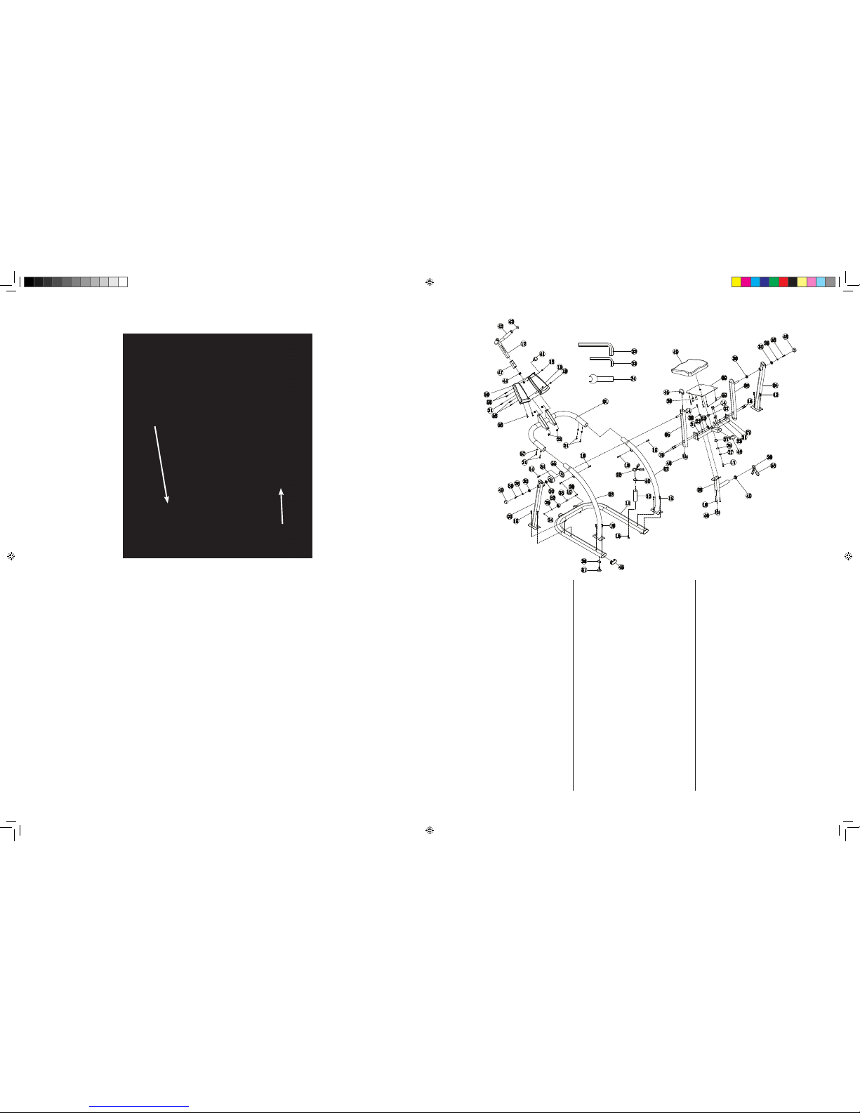
There are 2 wheels attached to the front leg support of the Ab Coaster® in order to aid in the moving and
storage of the unit.
Keep stored in a cool, dry place. If placed in long-term storage, you should cover the unit with
a cloth or other material to protect the unit from excessive dust or dirt accumulation.
Maintenance:
Keep unit clean and free of debris. Wipe periodically with cloth to keep track clean.
MOVING AND STORING THE AB COASTER® CTL
RESISTANCE TRAINING (Weights Not Included)
USING ADDED WEIGHT FOR RESISTANCE: There is a weight post underneath the Seat of the
Ab Coaster® CTL for adding weights (not included) for extra resistance during exercise.
CAUTION:
Do not add more than 40 lbs. of weight in total to the post (4 plates of 10 lbs. each). Use safety clip when
adding weights (clip not included). Before adding any weight, ensure that you are able to perform the
exercise with proper form without any additional weight.
Ple ase visi t www .AbCoast erC lub.co m and w ww. AbCoa ste rBl og.com
to view video of p rop er usage o f the mach ine.
WARNING: As with any physical exercise routine, injuries may result from incorrect usage of equipment
or excessive training.
6 7
PARTS LIST & VIEW
NO. Part Name Specification QTY (PCS)
01 arm plate support frame 1
02 side frame 2
03 left support frame 1
04 right support frame 1
05 left swing arm 1
06 right swing arm 1
07 knee pad support frame 1
08 knee pad weight post 1
09 knee pad plate 1
10 frame weight post 1
11 base frame 1
12 adjustable U handle 1
13 arm plate assembly 1
14 phillips screw ST4.8*15 4
15 M10xL70 hex screw M10*L70, (15mm thread) 1
16 M10xL55 hex screw M10*L55, (15mm thread) 4
17 M10xL25 hex screw M10*L25, full thread 1
18 M10xL25 hex screw M10*L25, full thread 4
19 M10xL15 hex screw M10*L15, full thread 14
20 M8xL45 hex screw M8*45 (15mm thread) 2
21 M8xL15 hex screw M8*L15, full thread 5
22 M10 nut M10 4
NO. Part Name Specification QTY (PCS)
23 M10 nut white nylon M10 white nylon 4
24 M8 nut white nylon M8 white nylon 2
25 flat washer OD16*ID8*1.5 2
26 flat washer OD30*ID11*T2.5 2
27 spring washer ø10 1
28 clamp match ø45*2.0 th=ubing 2
29 ø38*ø10.5*ø2 1
30 bearing model: 61904Z OD37*ID20*T9 4
31 flat washer OD20*ID11*2.0 4
32 S8 hex screw S8 1
33 S6 hex screw S6 1
34 S17 4mm thickness 1
35 roller bushing ø12.5*ø8*33 2
36 leveler orientation 63*45*3 6
37 ø38 nylon bushing OD38*ID25*H19 2
38 seat swivel bushing ø25*T8 3
39 ø23*37 2
40 weight post end cap match ø45*2.0 tubing 2
41 handle adjustment knob M16*1.5P 1
42 handlebar foam ø38*3*150,match ø32*1.5 tubing 2
43 handlebar end cap matchø32*2.0 tubing 2
44 square end cap match 32*32*1.5 tubing 1
NO. Part Name Specification QTY (PCS)
45 oval end cap match oval100*50*2.0 tubing 2
46 oval tubing match oval 80*40*2.0 tubing 6
47 square tubing ø40*2.0ø32 tubing 1
48 round tubing ø48*25,match ø42 2
49 knee pad 410*380*80 1
50 arm pad L310*W150*H120 2
51 leveler ø50*67,M10 6
52 roller ø47*27,34g 2
53 M10 nut cover match M10 nut 4
54 swing arm cover ø100*37 1
55 swing arm cover ø92*8 1
56 clamp cover 25*10*44 4
57 arc washer ø22*ø8.5*1.5T 4
58 M10xL15 hex screw M10*L15,full thread 14
59 M8xL15 hex screw M8*L15,full thread 4
Wei ght post
for r esi stance
tra ini ng
Wei ght post
for s tor age
AbC_CTL_MAN_V2_100519.indd 7-8 5/28/10 2:31 PM
Page 5
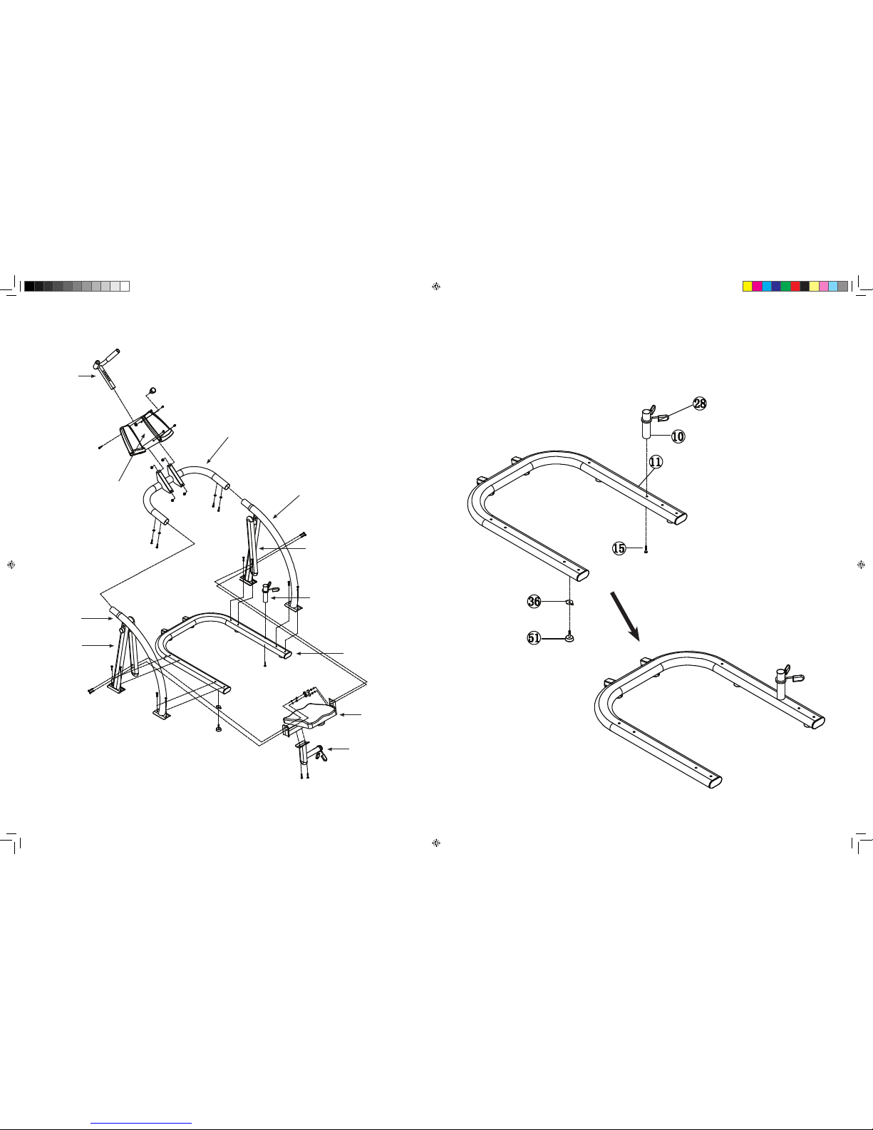
ASSEMBLY OVERVIEW STEP-BY-STEP ASSEMBLY
98
STEP 1:
Attach Weight Storage Post to
Bottom Frame.
NOTE: Half-tighten all screws until
assembly is complete.
TOP
FRAME
SIDE
FRAME
ARMREST
CONSOLE
SEAT
IMPORTANT: Remove all parts from packing and inspect for damage.
Retain packing materials if possible.
WEIGHT
POST
WEIGHT
STORAGE
POST
BOTTOM
FRAME
SWING
ARM
SIDE
FRAME
SWING
ARM
HAND
GRIP
AbC_CTL_MAN_V2_100519.indd 9-10 5/28/10 2:32 PM
Page 6
10 11
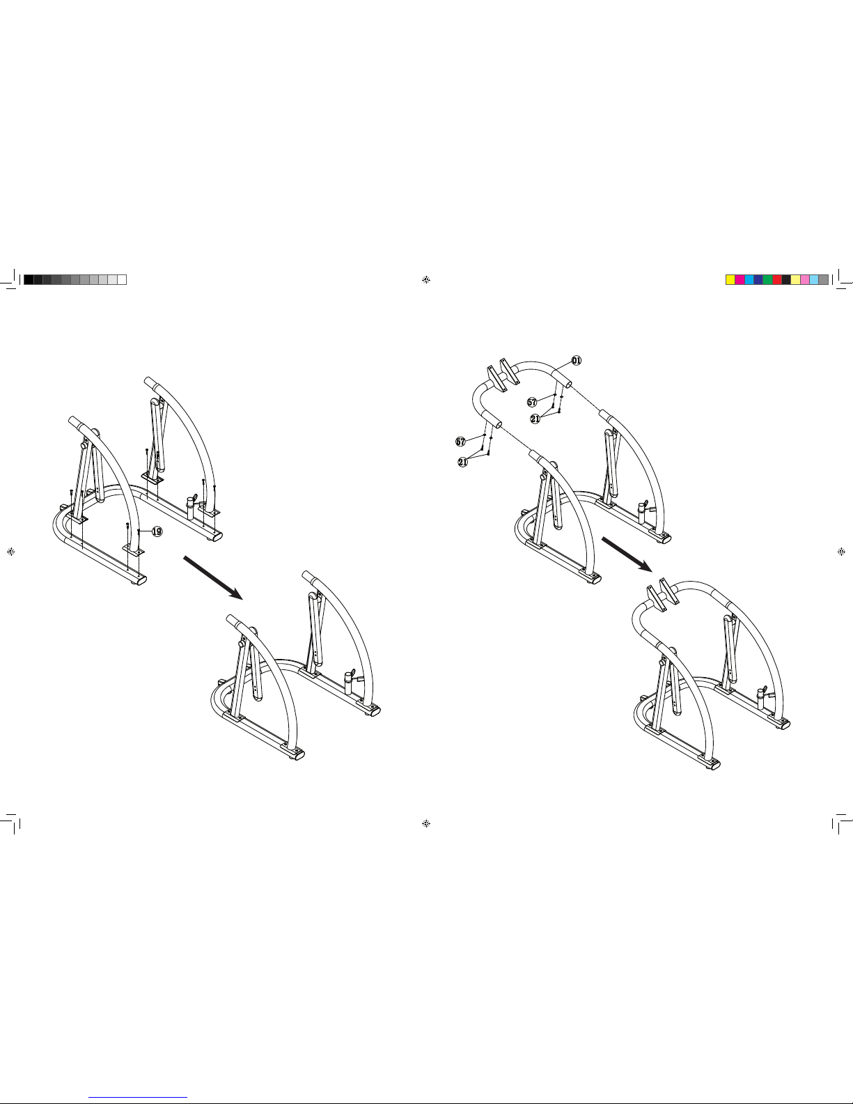
STEP 2:
Attach Side Frame and Swing Arm to both sides of Bottom Frame.
NOTE: Be sure to use correct size screws as indicated. Half-tighten
all screws until assembly is complete.
STEP 3:
Attach Top Frame to both Side Frames.
AbC_CTL_MAN_V2_100519.indd 11-12 5/28/10 2:32 PM
Page 7
12 13
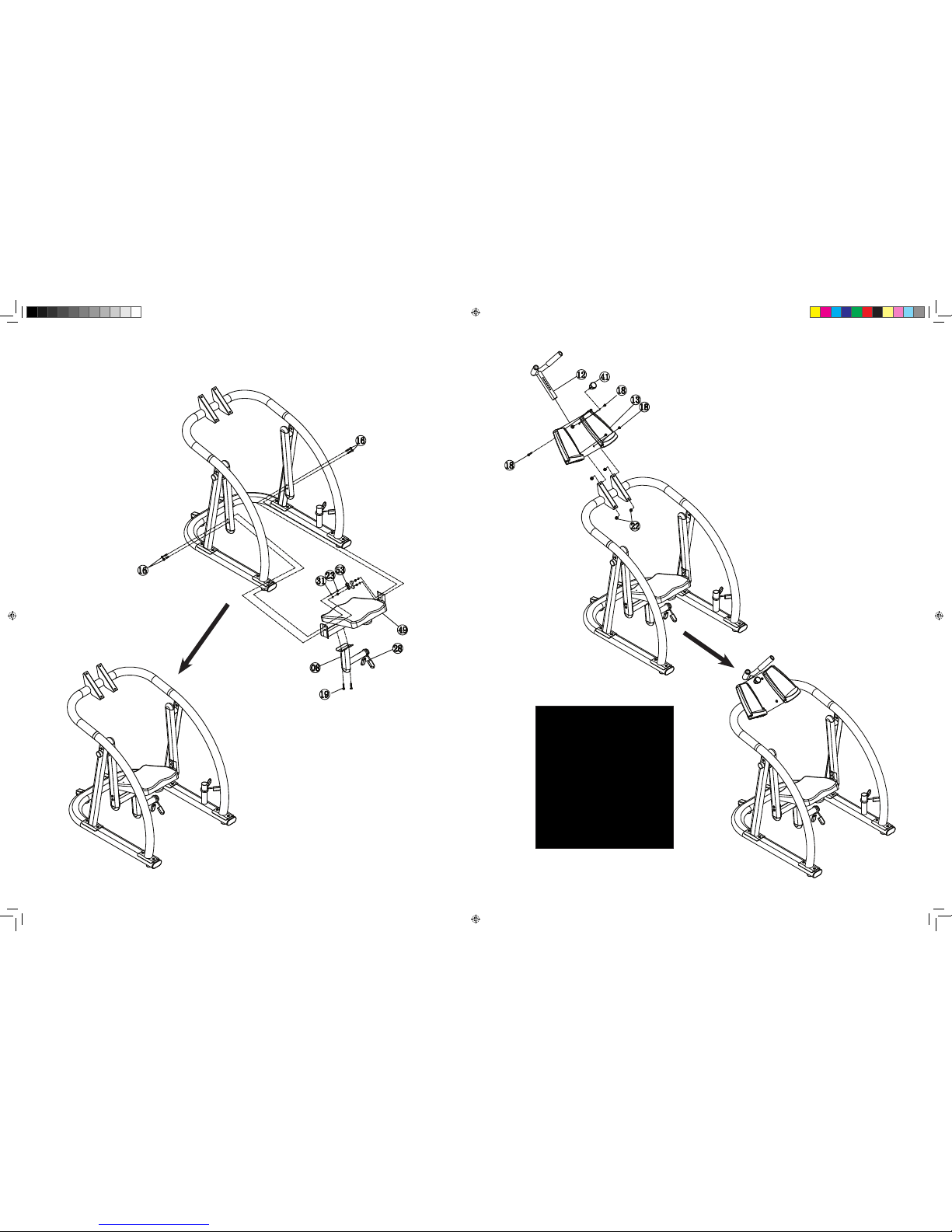
Attach Arm Rest Console to Top Frame, and then
attach Hand Grip to Arm Rest Console.
STEP 5:
Adjustable
Hand Grip
Insert Adjustable
Hand Grip into slot
as shown and attach
with screw in back
and secure with
pop pin in front.
Attach Weight Post to Seat and then attach Seat to both Swing Arms.
STEP 4:
AbC_CTL_MAN_V2_100519.indd 13-14 5/28/10 2:32 PM
Page 8
Manufacturer’s Limited Warranty – AB COASTER® CTL
The manufacturer warrants that your Ab Coaster® is free of defects in materials
and workmanship and will, at its option, repair or replace any defective Ab Coaster® that
is returned to it. Except as described in the following sentence, all parts and components
of the Ab Coaster are warranted for three (3) years from the original date of purchase. All
pads are warranted for ninety (90) days from the date of original purchase.
This warranty is valid only in accordance with the conditions set forth below:
1. Normal wear and tear are not covered by this warranty.
2. The warranty extends only to the original purchaser and is not transferable.
In addition, proof of purchase must be demonstrated.
3. This warranty is void if the product has been subject to accident, misuse, abuse,
improper maintenance or repair, or unauthorized modification.
4. This limited warranty is the only written or express warranty given by the
manufacturer. Any implied warranty of merchantability or fitness for a particular
purpose on this product is limited in duration to the duration of this warranty.
5. Repair or replacement of the product (or, if repair or replacement is not feasible,
a refund of the purchase price) is the exclusive remedy under this warranty.
The manufacturer shall not be liable for any incidental or consequential damages
for breach of this warranty or any implied warranty on this product.
MANUFACTURER MAKES NO WARRANTY OTHER THAN THE WARRANTY SET FORTH
HEREIN. SUCH WARRANTY IS IN LIEU OF ALL OTHER WARRANTIES, EXPRESS
OR IMPLIED, INCLUDING BUT NOT LIMITED TO ANY IMPLIED WARRANTY OF
MERCHANTABILITY OR FITNESS FOR A PARTICULAR PURPOSE.
SERIOUS INJURY COULD OCCUR IF THESE PRECAUTIONS ARE NOT OBSERVED.
• Read all warnings and obtain proper instruction on use of this machine prior to using.
• Obtain a medical exam prior to beginning an exercise program.
• Keep head, limbs, fingers and hair clear of all moving parts.
• Inspect machine prior to use. Do NOT use if it appears damaged or inoperable.
• Do NOT attempt to fix a broken or jammed machine. Notify floor staff.
• Use the machine only for intended use. Obtain instruction and DO NOT modify the machine.
• Children must not be allowed near this machine.
• Teenagers must be supervised in the use of this machine.
• DO NOT REMOVE THIS LABEL. REPLACE IF DAMAGED.
14 15
WARNING
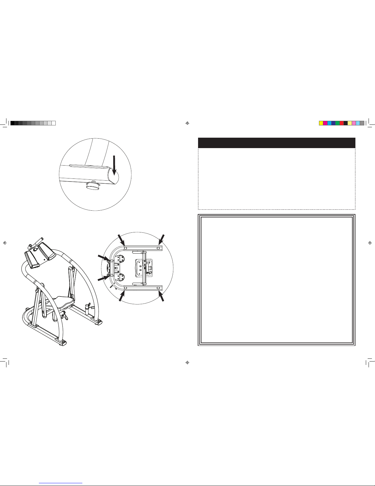
Use hex key tool to firmly tighten all screws. Be careful not to cross thread or overtighten
screws. The assembly process is now complete. Adjust LEVELERS located under front and rear feet
as needed.
STEP 7:
6 Levelers on
underside of unit.
STEP 6:
Attach Plastic Covers.
AbC_CTL_MAN_V2_100519.indd 15-16 5/28/10 2:32 PM
 Loading...