

Installation and
directions for use
HERU 14 S AC, HERU 19 S AC
HERU 35 S AC, HERU 52 S AC
UL VERSION

CONTENTS
UNIT DESCRIPTION . . . . . . . . . . . . . . . . . . . . . . . .3
INSTALLATION AND SECURITY . . . . . . . . . . . . . .4
”USE” ”SECURITY” ”MOUNTING””WARRANTY” . . . . . .4
”PLACING” ”FREE SPACE”
”SCHEMATIC DIAGRAM FOR PLACING” . . . . . . . . . . . . .5
STARTING UP THE UNIT . . . . . . . . . . . . . . . . . . . .6
CONTROL DIAGRAMS . . . . . . . . . . . . . . . . . . . . .7
REGULATION FUNCTIONS . . . . . . . . . . . . . . . . . .8
OPERATING THE CONTROL UNIT . . . . . . . . . . . .9
VIEW MODES 1-4 . . . . . . . . . . . . . . . . . . . . . . . .10
MAIN MENU . . . . . . . . . . . . . . . . . . . . . . . . . . . .11
”FAN SPEED” MENU . . . . . . . . . . . . . . . . . . . . . .11
”TEMPERATURE” MENU . . . . . . . . . . . . . . . . . . .11
”BOOST” MENU . . . . . . . . . . . . . . . . . . . . . . . . .11
”OVERPRESSURE” MENU . . . . . . . . . . . . . . . . . .12
”WEEK TIMER” MENU . . . . . . . . . . . . . . . . . . . .12
”UNIT ON/OFF” MENU . . . . . . . . . . . . . . . . . . . .13
”ALARMS” MENU . . . . . . . . . . . . . . . . . . . . . . . .13
”SETTINGS” MENU . . . . . . . . . . . . . . . . . . . . . . .14
THE ”SERVICE MENU” . . . . . . . . . . . . . . . . . .14-21
”FILTER MEASUREMENT” ”AC FAN SETUP” . . . . . . . . . .15
”DISPLAY CONTRAST” ”BOOST” ”OVERPRESSURE” . . .16
”ALARM””CO2” . . . . . . . . . . . . . . . . . . . . . . . . . . . . . .17
”RH” ”HEATER” ”COOLER” . . . . . . . . . . . . . . . . . . . . .18
”SUPPLY LIMITS” ”REGULATION MODE”
”SUMMER COOLING” . . . . . . . . . . . . . . . . . . . . . . . . . .19
”FREEZE PROTECTION”FLOW DIRECTION”
”LOAD/SAVE SETTINGS” ”VERSION INFO” . . . . . . . . . . .20
”DEVICE PAIRS” . . . . . . . . . . . . . . . . . . . . . . . . . . . . . . . .21
OTHER FUNCTIONS . . . . . . . . . . . . . . . . . . . . . .21
SERVICE HERU S . . . . . . . . . . . . . . . . . . . . . . .22-23
ACCESSORIES . . . . . . . . . . . . . . . . . . . . . . . . . . .24
SPARE PARTS . . . . . . . . . . . . . . . . . . . . . . . . . . .25
ERROR DETECTION DIAGRAM . . . . . . . . . . .26-27
ERROR DETECTION . . . . . . . . . . . . . . . . . . . . . . .28
INTERNAL SETTINGS . . . . . . . . . . . . . . . . . . . . .29
TECHNICAL INFORMATION
DIMENSIONS . . . . . . . . . . . . . . . . . . . . . . . . . . .30
TECHNICAL . . . . . . . . . . . . . . . . . . . . . . . . . . . . .31
SOUND DATA . . . . . . . . . . . . . . . . . . . . . . . .32-33
PRESSURE-FLOW DIAGRAMS . . . . . . . . . . . .34-35
WIRING DIAGRAMS . . . . . . . . . . . . . . . . . . .36-37
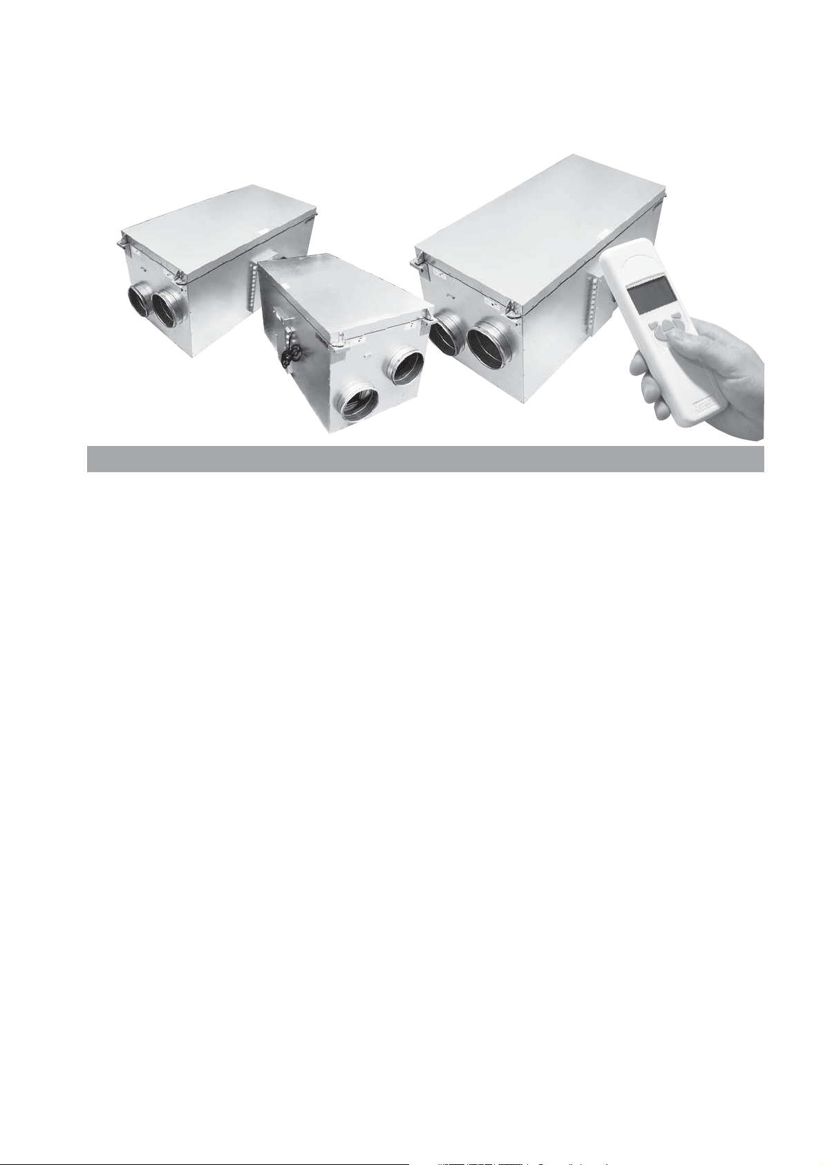
This ”Installation and directions for use” contains following products:
HERU 14 S AC, HERU 19 S AC, HERU 35 S AC and HERU 52 S AC.
IMPORTANT! Please read this manual before installing the unit.
HERU 35 S AC
UNIT DESCRIPTION
HERU 52 S AC
HERU 14 S AC
HERU 19 S AC
• HERU S is approved according to the standard
UL 1812 ”Ducted Heat Recovery Ventilators” and
CSA-C22.2 No. 113 ”Fans and Ventilators”.
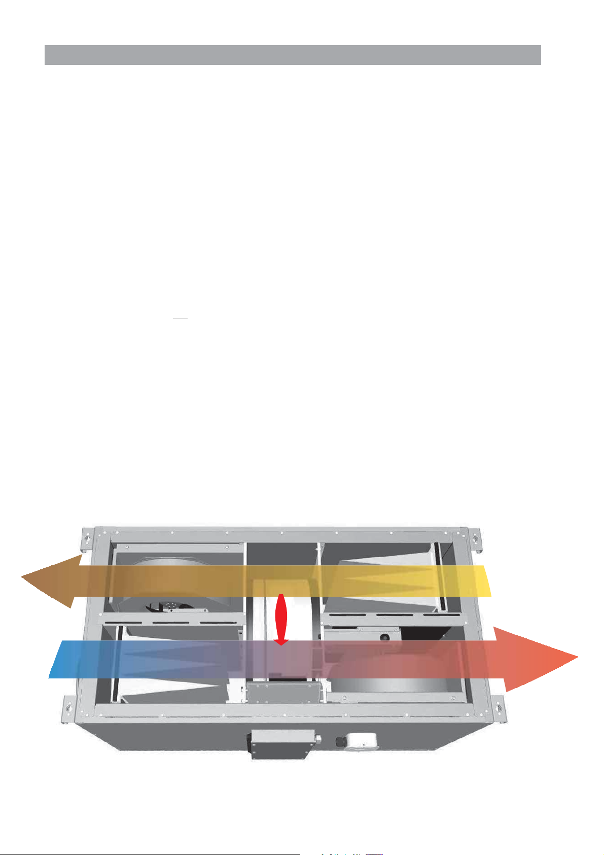
• HERU S is a heat recovery unit (HRV) or an energy recovery unit (ERV). It is designed for supply
and exhaust air ventilation combined with heat
and cool recovery.
• HERU S can be used in homes, offices, apartments
etc. where there is a need for:
-clean. filtered and fresh air
-high temperature efficiency
-energy saving
-low sound levels
-safe operation
• HERU S;
- has a rotating heat exchanger, of hygroscopic or
non-hygroscopic type and is manufactured of aluminium, placed centrally in the unit. The ERV exchanger has a humidity efficiency of up to 85%.
The HRV exchanger has a temperature efficiency
of up to 85%.
- has backwardcurved centrifugal fans with maintenance free external rotor motors, which are connected with quick contacts, and are easily to
remove for cleaning.
- has built-in control for heating/cooling.
- can be fitted with a built-in electric heater.
- has as standard, disposable bagfilter,
class MERV 13.
- has a wireless remote controller for the operation
and monitoring of the unit.
- has a double skinned galvanised sheet steel casing
with intermediate insulation.
• The HERU S can be mounted in either warm or
cold space.
• The HERU S is delivered galvanized.
• All HERU S are operated via a wireless remote
controller which can operate and to preset the required parameters as well as monitor the unit’s
status. The operating range is approximately 50
meters/164 feet.
The antenna which is placed next to the unit can
have the range reduced if there are heavy reinforcing bars in the concrete structure and it should
then be moved either to a position where the signal is not shielded or nearer to the controller.
WARRANTY
The warranty is only valid under condition that the
HERU S unit is installed, adjusted and has been
record by a qualified person according to this
”Installation and directions for use”, and that regular
maintenance had been made.
NOTE!
Östberg Americas Inc. reserve the right to make
changes without further notice.
3
INSTALLATION AND SECURITY
USE
• When installing HERU consideration must be
given to any approval authority requirements and
recommendations concerning siting, accessibility,
electrical connections, etc.
• The HERU unit is accessible for the user, according to IEC 60335-2-40, to by themselves do the
service and maintenance, according to this
Directions for use. But before this work the unit
must be currentless.
With reservation according to IEC 60335-2-7.12
”This appliance is not intended for use by persons
(including children) with reduced physical, sensory or metal capabilities, or lack of experience and
knowledge, unless they have been given supervision or instruction concerning use of the appliance
by a person responsible for their safety.”
”Children should be supervised to ensure that they
do not play with the appliance.”
• The HERU unit should be storage in a sheltered
and dry place before installation.
• Dimensioned air flow should not exceed 60% of
the unit's maximum capacity.
• Check at regular intervals that supply air and exhaust air works.
• To avoid condensation in the unit during the cold
season, the unit should not be turned off for a
longer period. When installed in warm moisturre
environment as e.g. bathroom and utilityroom condense may appear on the outside of the unit at low
outside temperatures.
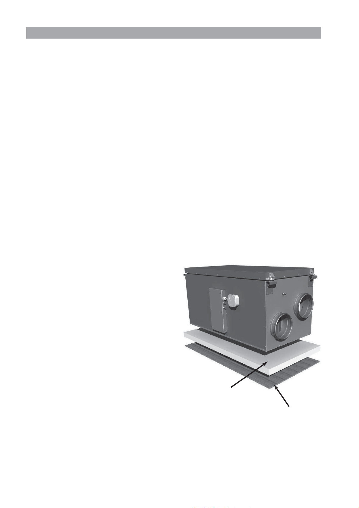
MOUNTING THE HERU S
• HERU S should be installed according to the
assembly instruction, see picture below.
• Place the unit on a high density insulation board,
min. 50 mm.
• Supply and extract air must be duct connected on
the same side of the unit.
• Acoustic silencer should be planned with the help
of sound data and required sound levels.
• Use duct clamp or flange with encompassing insulation when connecting to duct.
• If the supply and the extract air ducts are installed
in a cold space they should be insulated. To prevent condensation the supply air duct should also
be insulated if installed in warm space at low supply air temperatures.
• The fresh air and exhaust air duct should always be
condense insulated.
• The ducts should be insulated all the way towards
the unit.
• The duct sensor GT7 should be mounted in the
supply air duct, and the antenna on a suitably position beside the unit (not against metal).
• If a heating coil is connected a cut off damper must
be mounted in the fresh air duct.
• Cooker hoods must not be connected to the
HERU S.
SECURITY
Attention! Do not apply electric power until after
completion of the installation. Ensure the installation
and wiring is in accordance with CEC, NEC and
local electrical codes..
• Attention, look out for sharp edges and corners on
the HERU unit and fans.
• Consider the weight of the unit. See page 31.
• Before maintenance work the HERU unit must be
currentless. If there is a need of changing or complement any electrical components, it should be
done by a qualified person.
• The HERU unit includes rotating parts that could
cause serious danger on the occasion of contact.
This is why the unit must be duct connected and
the lid closed with the screws tightened, before
starting up the unit.
• After the current is cut for service and maintenance the electric heater may still be warm.
• Make sure that the access cable is not damage at
mounting and installation.
• The HERU S needs a permanent electrical supply.
The unit must be connected via a safety switch.
Any electrical connections must be made by a qualified electrician.
INSULATION BOARD
min. 50 mm
FLOOR
4
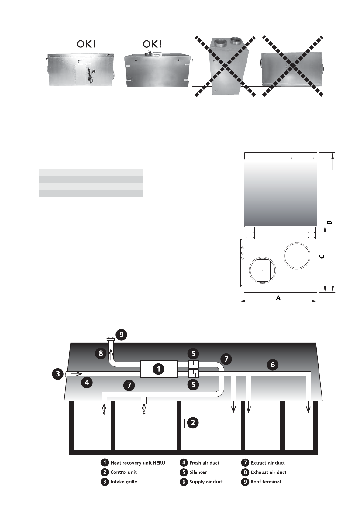
PLACING THE HERU S UNIT
A B C D
The HERU S should be installed with the lid upwards (A) or on the side (B). Because of the risk of injury
we do not recommend installing the unit vertically (C) or with the lid downwards (D). Allowances must be
made to access the unit for servicing or maintenance.
CLEARANCEE FOR SERVICING AND MAINTENANCE
mm A+D B C
®
H E R U
50 S 2, 75 S 2, 100 S EC 21
®
H E R U
130 S 2, 130 S EC 2 24 39
H E R U®180 S 2, 180 S EC 2 28 48 24
7/8311/2
16
3/8201/2
Clearance for servicing and maintenance
7/8
SCHEMATIC DIAGRAM FOR HERU S PLACED IN AN ATTIC
5
STARTING UP THE UNIT
Note! Important information before starting!
WARNING!
Improper installation, adjustment, alternation, service or maintenance can cause property damage, personel injury or loss of life.
Installation and service must be performed by a
qualified installer or service agency.
Carefully read through the manual before starting
up the unit.
• Note! Always mount the temperature sensor GT7
in the supply air duct. See page 7 and 36-37. GT7
is connected at the relay card. The temperature
sensor GT7 is placed in the control cabinet when
delivered.
• The antenna should be mounted outside the unit.
The antenna for HERU S is delivered connected,
is placed in the control cabinet.
Note! The antenna should not
any metal area or metal items as this will shield
the signal.
The antenna should be mounted as central as
possible. This to achieve the best signal all over
the house. If neede an extension cord is available
as an accessorie.
be mounted against
age, always check so the unit is starting up again.
• HERU S is supplied for right handing applica-
tion, see picture below. If the unit is installed left
handed, and no electrical heater is fitted, changes
can be made in the ”Service Menu” and in the submenu ”Flow Direction”. See page 20.
• Important when adjusting the flow: Go to Service
Menu (password 1199), choose “AC-motor setup”.
This disable functions such as Summer cooling or
Boost during flow adjustment. The preset fan
speed is standard. See page 11.
When adjusting the airflow of AC-fans there is a
possibility to change the voltage for the different
fan speeds via the separate transformers for supply
resp. exhaust fan. Normal operation should be
done in standard mode. HERU 14 S/19 S has 5step transformers and HERU 35 S/52 S has 7-step.
See wiring diagrams on pages 36-37.
Note! When ajusting fan speed manully, make
sure that the speed keeps the sequences.
• All HERU can be fitted with a built-in electric
heater. Choose heater ”On/Off” according to the
instruction on page 18.
• Install the 3 AA batteries in the wireless control
unit that are placed inside the HERU when delivered.
• HERU S starts automatically (with a few minutes
delay) when the power is switched on, or alternative with the wireless control unit. At power out-
EXHAUST
AIR
FRESH
AIR
• Set the temperature according to the instruction
on page 11.
• Save settings according to the instruction on page 20.
• Note! The unit must not be operating without
filter.
EXTRACT
AIR
SUPPLY
AIR
CONTROL CABINET
6
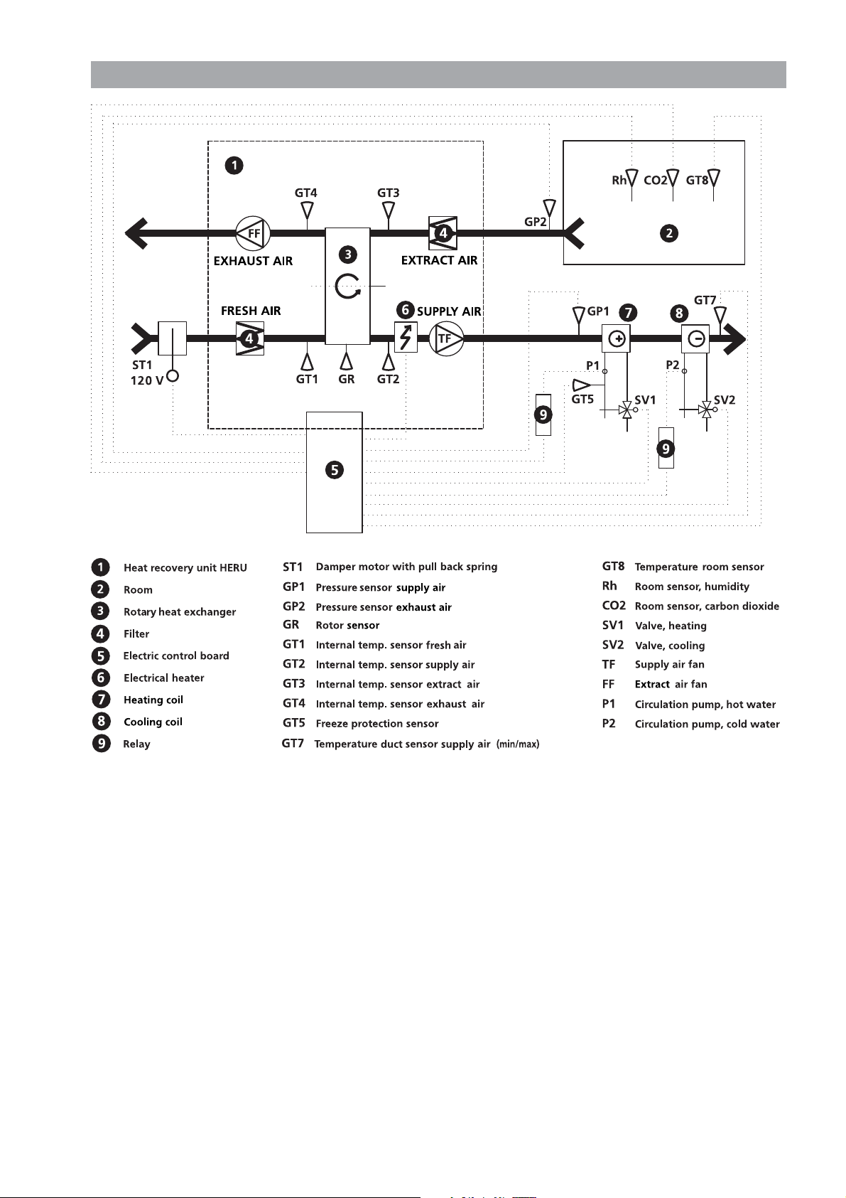
CONTROL DIAGRAM HERU
®
S
shows all sensors, flow direction right
*Accessories
*
*
*
*
*
*
*
*
*
*
*
*
*
7

REGULATION FUNCTIONS
REGULATE THE TEMPERATURE
The air temperature can be regulated either for constant supply air temperature, constant room temperature or constant exhaust air temperature.
For constant room temperature a sensor should be
placed in the room for room regulation (this is also
suitable when a cooling coil is incorporated in the
system).
Exhaust air regulation functions in a similar way
but with the difference being that the sensor is
placed in the extract air duct.
The temperature can be regulated in 5 sequences:
1.Cooling recovery + After cooling: The regulation
unit can control a cooling coil (e.g. cooling water
from bedrock), when the cooling recovery from
the rotor is not enough.
2.Cooling recovery or regulated fresh air cooling:
The rotary heat exchanger starts if the extract air
temperature is lower than outside temperatur.
Fresh air cooling: The outside temperature is lower
than desired room temperature. The rotor regulate
the supply air temperature.
3.Outside temperature = desired temperature: When
the outside temperature is the same as desired sup-
ply air temperature the rotor stops.
4.Heat recovery: The rotary heat exchanger starts to
recover the warmer room temperature.
5.Heat recovery + heat: In climate conditions where
the rotary heat exchanger, in spite of its high effi-
ciency, is not sufficient to reach the desired supply
air temperature, the controller can regulate either
the built-in electric duct heater or a heating coil.
FAN CAPACITY
Airflow (fan speed) is regulated via the week timer
that can be programmed for specific time points
when the fan speed should change from one speed to
antoher (e.g. home or away setting). A special feature
is that you can pressure compensate when supplementary heating, using an open fire or stove (the
exhaust air fan then drops to a lower speed).
The wireless control unit can also manually adjust
the fan speed and even boost the airflow for an indicated length of time. The fan speed can also be controlled by a carbon dioxide (CO
(RH) sensor so that the unit gives a higher airflow
(boost) when the maximum limit value is reached.
”Summer Cooling” is a function where you can use
the cool outside temperature at night, to cool down
the inside air. The fan speed is boosted when the
ratio between the outside temperature and the
exhaust air temperature is within the programmed
criteria.
Via the wireless control unit the HERU can be put in
an ”Off mode”, which means that the motors for fans
and rotor are ”Off” but the unit is ”Stand by”. If there
is a requirement of totally cut off power, a switch
must be mounted on the mains.
Boosting the airflow for a specified time can be done
via the wireless control, there is also a opportunity to
do that via a timer connected to the ”0” and ”Boost”
connection on the PCB. With the connectors closed
the boost function will be ”On”.
) and humidity
2
Regulated
cooling coil
0-100%
Rotor 100%
1.
Cooling recovery
+
Cooling coil
Regulated rotor
0-100%
2.
Cooling recovery
Regulated rotor
0-100%
4.
Heat recovery
or Fresh air cooling
3.
Outside temperature = Desired temperature
8
Regulated
after heating
0-100%
Rotor 100%
5.
Heat recovery
+
After heat
OPERATING THE CONTROL UNIT
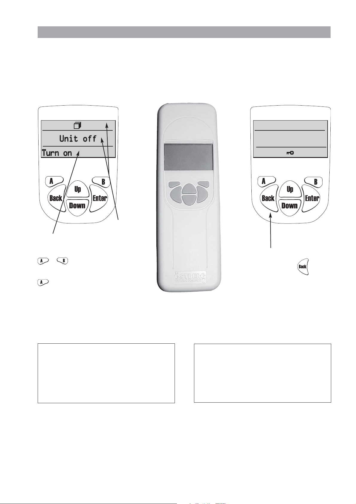
StdStd
SYSTEMSYSTEM OK......
Information of the units current status such as temperature, fan speed, the rotor temperature efficiency when
operating, heat respectively cooling needs is shown in the VIEW MODE 1, 2, 3 and 4. These menus is normally
not lit up for battery-saving purposes but is lit up after the first press of the button and is switched off after
about 2 minutes of not being in use.
The control unit automatically returns to VIEW MODE 1 after one minute when one has viewed other submenus.
Note! At new setting a delay of 15 seconds should be taken into consideration.
Bottom row
shows the possible
choices with key
E.g turn on/off
the unit with the
USER INFORMATION FOR RF DEVICE:
Changes or modifications not expressly approved by the
party responsible for compliance could void the user’s authority to operate the equipment.
This exuipment has been tested and found to comply
with the limits for Class B digital device, pursuant to part
15 of the FCC Rules. These limits are digned to provide
reasonable protection against harmful interference in a
residential installation. This equipment generates, uses and
can radiate radio frequency energy and, if not installed and
used in accordance with the instruction, may cause harmful interference to radio communications. However, there
Top row
and
middle field
displays
current
or .
values
and
activities.
key.
FCC ID: A8W-4020528
This device complies with part 15 of the FCC Rules
and RSS-210 of IC Rules. Operation is subject to
the following two conditions: (1) This device may
not cause harmful interference, and (2) this device
must accept any interference received, including
interference that may cause undesired operation of
the device.
To activate or disable
the keylock;
press down the key
for 3 seconds.
FCC ID: ASW-4020527
This device complies with part 15 of the FCC Rules
and RSS-210 of IC Rules. Operation is subject to
the following two conditions: (1) This device may
not cause harmful interference, and (2) this device
must accept any interference received, including
interference that may cause undesired operation of
the device.
is no guarantee that interference will not occur in a particular installation. If this equipment does cause harmful
interference to radio or television reception, which can be
determined by turning the equipment off and on, the user
is encouraged to try to correct the interference by one or
more of the following measures: -Reorient or relocate the
receiving antenna. -Increase the separation between the
equipment and receiver. -Connect the equipment into an
outlet on a circuit different from that to which the receiver is connected. Consult the dealer or an experienced
radio/tv technician for help.
9
CO2
+
CO2
+
...
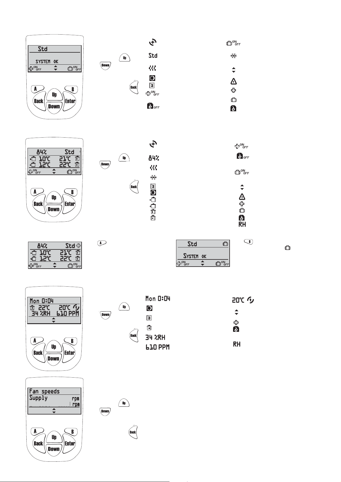
VIEW MODE 1
+
960
1060
Extract
SYMBOLS THAT CAN BE DISPLAYED IN VIEW MODE 1:
In order to go to
view mode 2, 3
or 4 press
or .
In order to
return to view
mode 1, press .
= Indicates that the rotor is operating.
+
= heat recovery
- = cooling recovery
= Fan speed. Choose from min,
standard, medium, max.
= Symbol indicates that
the heating coil is on.
= Summer cooling is active.
= Week timer is active.
= Function of A-key.
Press A-key to regulate ”boost”
of supply & extract air flow.
= Function of B-key.
Press B-key to turn off
pressure compensation.
VIEW MODE 2
SYMBOLS THAT CAN BE DISPLAYED IN VIEW MODE 2:
In order to go to
view mode 3
or 4 press
or .
In order to
return to view
mode 1, press .
IN VIEW MODE 1 AND 2 BOOST OFF/ON AND AWAY OFF/ON CAN BE CHOOSEN.
Press key to choose Boost off/on of the
supply & extract air flow for a specific time (time
and fan speed settings during the boost
is made in the Service menu ”Boost” page 11).
When the ”plus”
right corner, the boost is activated.
+
symbol is displayed in the
= Indicates that the rotor is operating.
= heat recovery
- = cooling recovery
= Temperature efficiency.
= Symbol indicates that
the heating coil is on.
= Symbol indicates that
the cooling coil is on.
= Week timer is active.
= Summer cooling is active.
= Outside temperature.
= Exhaust air temperature.
= Supply air temperature.
= Extract air temperature.
= CO
compensation is active.
2
= Function of B-key.
Press B-key to choose
”Away” on or off.
= Symbol indicates that
the cooling coil is on.
= Function of keys up and down
for view mode 2, 3 and 4.
= Alarm
= Indicates Boost is active.
= Indicates Away is active.
= Pressure compensation is active.
= Function of A-key.
Press A-key to regulate ”boost”
of supply & extract air flow
= Function of B-key.
Press B-key to turn off
pressure compensation.
= Function of B-key.
Press B-key to choose
”Away” on or off.
= Function of keys up and down
for view mode 1, 3 and 4.
= Alarm
= Indicates Boost is active.
= Indicates Away is active.
= Pressure compensation is active.
= RH compensation is active.
Press key to choose Away off/on.
When the symbol ”suitcase” is
displayed in the right corner, the away
mode is activated, i.e. the fan speed is
minimum.
9
In order to go to
view mode 2
or 4 press
or .
In order to
return to view
mode 1, press .
VIEW MODE 4 (only for HERU®EC)
In order to go to
view mode 2
or 3 press
or .
In order to
return to view
mode 1, press .
VIEW MODE 3
SYMBOLS THAT CAN BE DISPLAYED IN VIEW MODE 3:
= Display weekday and time.
= Indicates that Summer
cooling is active.
= Indicates that week timer
is active.
= Room temperature.
Sensor placed in room.
= Relative air humidity in per cent.
= Carbon dioxide level in PPM
(part per million).
SYMBOLS THAT CAN BE DISPLAYED IN VIEW MODE 4:
Displayes fan speed of supply and extract air in rpm.
At Constant pressure regulation the max speed, the fan speed and current pressure
sensor value is displayed in per cent.
= Supply air temperature
after the rotor.
= Function of keys up and down
for view mode 1, 2 and 4.
= Indicates Boost is active.
= Pressure compensation is active.
compensation is active.
= CO
2
= RH compensation is active..
10
”MAIN MENU”
In order to go forward in the menu from the View mode to the Main Menu press .
In the Main Menu is used to select the desired menu, after the choice is made with .
The procedure is the same in the submenu. In order to return to the previous page press .
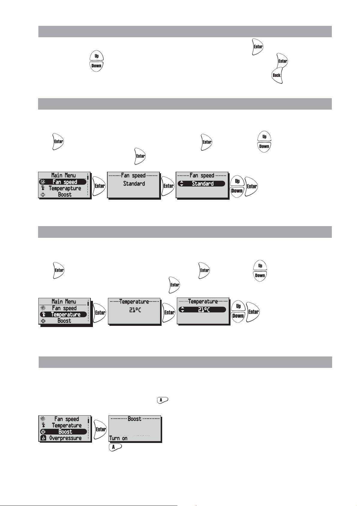
”FAN SPEED” MENU (Only for Heru
In this menu desired fan speed is chosen. You can choose from 4 speeds: Min, Standard, Medium and Max.
Normal operation should be done in standard mode
Press in order to go forward from the Main Menu. Press again and then in order to choose
the desired fan speed. Confirm with .
Made settings is overridden if Week Timer is activated.
®
AC)
”TEMPERATURE” MENU
In this menu desired temperature is chosen (supply air, extract air or room temperature) depending on what
kind of regulation that is choosed, see page 19.
Press in order to go forward from the Main Menu. Press again and then in order to choose the
desired temperature (15°C-30°C); .Confirm with .
Made settings is overridden if Week Timer is activated.
”BOOST” MENU
In this menu Boost On/Off is chosen. The time has the factory setting of 30 min. and fan speed Medium.
To adjust the fan speed and time, see page 16.
Boost is activated/disable (On/Off) with the key.
The Boost function can also be activated with an external switch with double pressure or timer.
See wiring diagram page 36-37. The Boost is On as long as the breaker is closed.
11
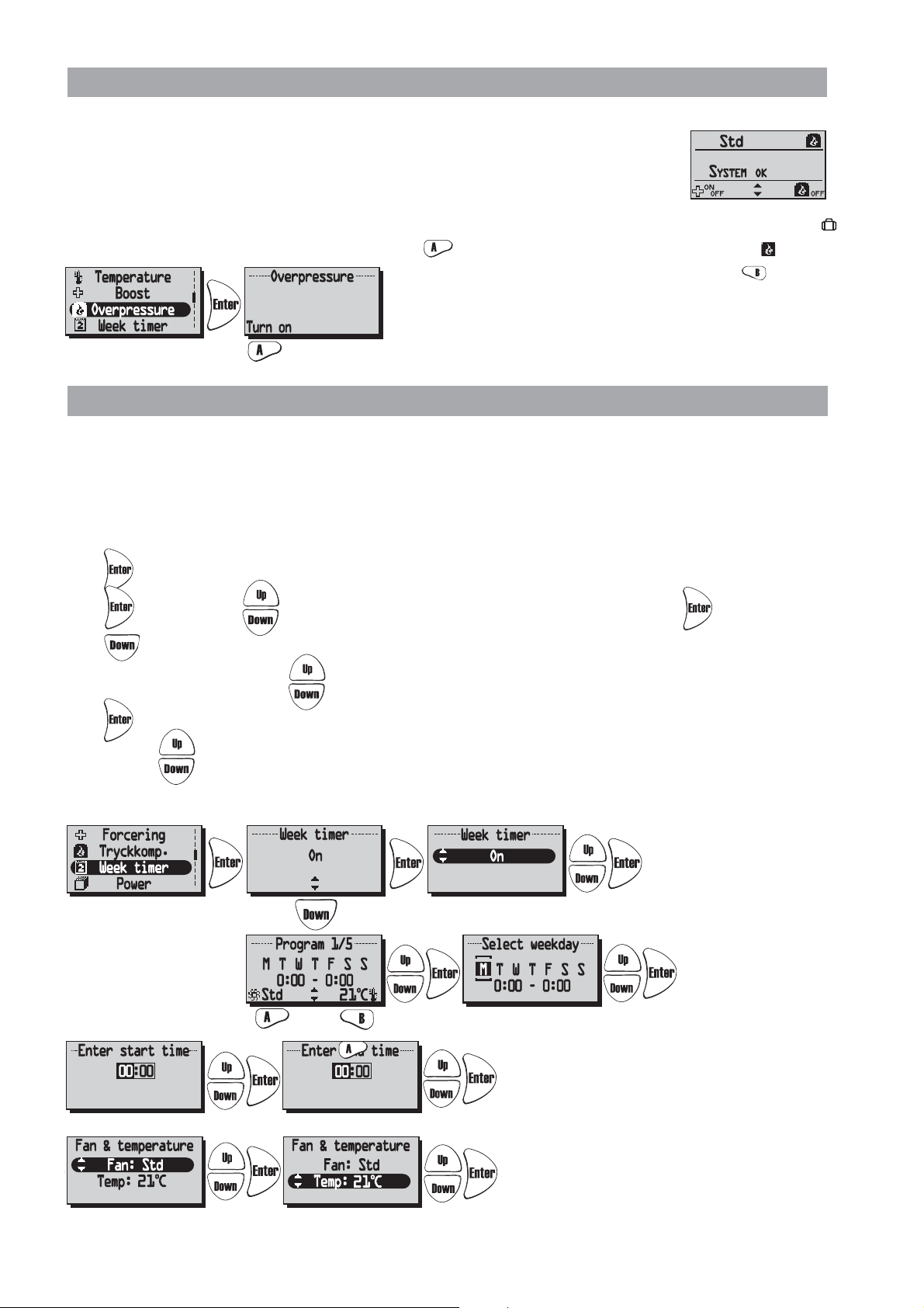
“OVERPRESSURE” MENU
Off
Overpressure is a special feature were you can pressure compensate when supplementary
heating using an open fire or stove. The extract air fan then drops to a lower speed
during set time.
In this menu Overpressure On/Off is chosen. The time has the factory setting of 15 min.
To adjust the time, see page 16.
Overpressure is activated/disable (On/Off) with the key.
When pressure compensate is
activated the symbol ”Away”
will be change to the symbol
”Overpressure” in View
mode 1 and 2.
Than press directly in the
View mode to turn off Overpressure.
“WEEK TIMER” MENU
When in normal operation the unit runs with the fan speed that was choosen in the “Fan Speed” menu and
the temperature that was choosen in the “Temperature” menu. A departure from these programmed values that
you periodically want to recall is done in this menu. For example if you want to have a lower flow/temperature
during the daytime when nobody is at home then there is the possibility to adjust this here.
Week timer. If end time is the same or less than start time the program will end the following day.
Press in order to go forward from the Main Menu.
Press again and then in order to choose off/on of the week timer. Confirm with .
Press to choose/adjust the desired program. There are 5 programs for the adjustment of the fan speed
and temperature available. Press to choose a program.
Press in order to go forward to choose a weekday, start time, end time, fan speed and temperature.
Use the keys to choose the settings of weekday, start time, and end time, fan speed (Min, Standard,
Medium, Max) and temperature (15°C-30°C).
Cont. next line.
Cont.
Cont. next line.
Cont
N.B! The activated Week Timer is overridden manuel settings of fan speed and temperature.
12

“UNIT ON/OFF” MENU
! Filtertimer
Reset
In the ”Unit On/Off” Menu you have the possibility of turning off the unit via the wireless control unit.
This will just put the unit in a stand by mode.
NB! The unit must be currentless during service and maintenance.
Press in order to go forward from the Main Menu. Press in order to choose on/off of the unit.
To avoid condensation in the unit during the cold season the unit should not be turned off for a longer period.
“ALARMS” MENU
This meny displayes alarms.
View mode 1 shows alarm and
View mode 2 shows what kind of alarm.
Alarms is shown for:
• ”Rotor failure” • ”Supply temp. low” • ”Rotor temp. low” • ”Fire alarm” • ”Freeze alarm”
• ”Sensor open” • ”Sensor shorted” • ”Overheating” • ”Filter alarm” • ”Fan failure” • ”Filtertimer”
Press in order to go forward from the Main Menu and to view status. If no alarm ”System OK” is displayed.
When alerting a dialogue box for the alarm is shown in the Main Menu and the display will flash.
“View alarms” is shown and the possibility for equalization is given.
Press to see the cause of alarm in a submenu. Control the cause and remedy the alarm.
Press to ”Clear all” and than .
Current alarm is viewed. When "Sensor open" and "Sensor shorted" press "Show"
to view which sensor GT 1-8 is alerting.
See Control diagrams on page 7.
In order to return to the previous pages press .
When alarm for Filter timer the alarm can equalize with Reset.
A reminder to change filter comes with a seven-day interval.
To restart the timer see ”Service Menu Alarm” page 17.
13
!

“SETTINGS” MENU
Are you sure?
No Yes
In this menu settings for weekday, time and what language is made.
Press in order to go forward from the Main Menu. Press again and then in order to choose weekday.
Press again and then in order to enter the time.
Press and then in order to choose a language. 4 languages are available: Swedish, Finnish, Russian
and English.
THE “SERVICE MENU”
In this menu a password is required in order to make adjustments. The password is 1199 and it can not be changed.
Press in order to go forward from the Main Menu.
The password is entered with the keys and every digit is confirmed with .
After the password 1199 to the Service Menu the question “Are you sure?” will be displayed.
Press for “No” or for “Yes”.
A
To go further to the different functions in the ”Service menu” press or .
14

SERVICE MENU: “FILTER MEASUREMENT”
ServicemenyServicemeny
FiltermätningFiltermätning
EC-motor setupEC-motor setup
Display kontrastDisplay kontrast
Är du säker?
Bör endast ändras
av installatör!
Standard (%)
Tilluft: 60%
Frånluft: 70%
EC-motor setupEC-motor setup
StandardStandard
Min
MediumMedium
Avbryt Ok
Standard (%)
Tilluft: 60%
Frånluft: 70%
EC fan setup
AC fan setup
--Fan speed-Standard
Service menu
Filter switches or pressure sensors are not installed as standard, and this is displayed:
If filter switches are installed and activated, setting for day and time is choosed when the unit should
boost to measure increased pressure over supply air filter GP1 and exhaust air filter GP2.
SERVICEMENY: “AC FAN SETUP”:
When adjusting the unit, the speed is set to
standard and functions that may affect the
fan speed, such as “Away” and “Boost”,
should be inactivated.
15

SERVICE MENU: “DISPLAY CONTRAST”
EC fan setup
AC fan setup
AC fan setup
Display contrast
Display contrast
Boost
Alarm
Display contrast setting. The contrast can be set between 0-63.
SERVICE MENU: “BOOST”:
Time settings for Boost and Fan speed. Boost means that during a specific time increases
the air flow. This boost can then be activated at the View mode 1 and 2, and in the Main Menu “Boost”.
Press in order to go forward from the Main Menu. Press again and then in order to choose
the desired duration.(10-240 min. with the interval of 10 min.)
Press on order to confirm and go forward to fan speed.
Choose the desired fan speed with (medium or max) and confirm with .
Boost is activated/disable (on/off) with the key.
A
SERVICE MENU: “OVERPRESSURE”
Time settings for Overpressure. Overpressure compensate is a special feature when supplementary heating
using an open fire or stove (the extract air fan drops to a lower speed during a specific time).
Press in order to go forward from the Main Menu. Press again and then
in order to choose the desired duration (5-60 min.).
D
16

SERVICEMENY: “ALARM”
Reset
Interval: 5 min.
Interval: 5 min.
Interval: 5 min.
2
2
2
Autom.reset: Off
Autom.reset: Off
In this menu alarm limits is set for Filter timer, Low temperature and setting for Fire sensor.
”Filter timer” can be set from ”Off” to ”6-12 months” and generates alarm for filter change.
Filter timer can not be used in combination with another filter measurement, see page 15.
We recommend filter change at least once a year.
To restart the filter timer press “Reset” with the -key.
Alarm limits for ”Low temperature”.
Alarm limit A: (+2 till +10ºC but must be lower than ”Alarm limit B”)
Alarm for low rotor temperature is displayed when the temperature is lower than set value. Normally nothing
needs to be done. If “Rotor Alarm” appairs at the same time as “Rotor temp. Low” the unit is stopped.
Alarm limit B: Supply air flow is reduced with one step when the temperature in supply air duct (GT7) is
lower than set value, and the temperature efficiency increases (the temperature can be change from +5 to
+12ºC but have to be higher than ”Alarm limit A”).
If the unit operating at Min. speed the extract air increases one step.
In menu ”Fire sensor” type of installed fire sensor is set.
Choose ”Normally open” NO or ”Normally closed” NC depending on the type of smoke detector.
Choose ”Autom.reset” On/Off.
SERVICEMENY: “CO2” Carbon dioxide level in PPM (part per million).
In this menu settings are made for regulation with installed CO2 sensor.
Press again and then in order to choose the Limit value (500-1400 PPM).
Press again and then in order to choose Interval (1-10 min.).
At levels above the limit value the fan speed will increase one step according to the set Interval value.
Current CO2 value is displayed in View mode 3, see page 10.
17

SERVICEMENY: “RH”
Interval: 5 min.
Interval: 5 min.
Interval: 5 min.
Afterblow: On
Afterblow: On
Afterblow: On
Relative air humidity in percent
In this menu settings are made for regulation with installed RH sensor.
Press again and then in order to choose the Limit value of boost (50%-100%).
®
HERU
AC: Press again and then in order to choose Interval (1-10 min.).
At levels above the limit value the fan speed will increase one step according to the set Interval value.
Current RH value is displayed in View mode 3, see page 10.
SERVICEMENY: “HEATER”
In this menu type of Heater is chosen to be activated.
If a heating coil is used a freeze protection sensor (GT5) must be installed, and a damper ST1 must be
mounted in the fresh air duct. The GT7 must be mounted after the Heater.
Press again and then in order to choose On or Off.
”Afterblow” function means that the fan continues to run for 2 min. when the unit is put Off,
if the heater is On.
SERVICEMENY: “COOLER”
In this menu a cooling coil can be activated if installed.
Press again and then in order to choose On or Off.
18

SERVICEMENY: “SUPPLY LIMITS”
5 5
5
Extract
Extract
Extract
Extract
Extract
Extract
Extract
Extract
In this menu the upper and lower limit value for the supply air temperature at room or exhaust air regulation is set.
Press again and then in order to choose a minimum limit value (15°C-19°C).
Press again and then in order to choose a maximum limit value (20°C-40°C).
SERVICEMENY: “REGULATION MODE”
3 different types of regulation modes can be used.
• At a constant supply air regulation the temperature sensor (GT7) is placed in the supply air duct and
a constant incoming air temperature is obtained.
• At room regulation a sensor (GT8) is placed in the room and a sensor (GT7) in the supply air duct
(minimum/maximum limitation) and then a constant room temperature is obtained (suitable when
a cooling coil is installed).
• The extract air regulation works in a similar way as the room regulation with the difference being that
the temperature is measured in the extract air duct.
Press again and then in order to choose Supply reg., Extract reg. or Room reg.
SERVICEMENY: “SUMMER COOLING”
If ”Summer Cooling” ”On” is chosen, the Summer cooling is activated when the extract air temperature is
higher than ”Extract HI” (19°C-26°C) and outside air is colder than ”Exhaust - ‘In OutDiff’ (1°C-10°C
difference between the temperature outside and extract air)".
Summer cooling is deactivated when extract air temperature is lower than ”Extract LO” (18°C-24°C)
or when the outside temperature is warmer than "Extract air - 'InOutDiff + 1,0ºC' ".
If Summer Cooling is activated, water cooling is disabled.
Press again and then in order to choose On or Off. In order to go forward in “Summer Cooling” press .
Cont. next line.
Cont.
5
Press again and then in order to choose 'InOutDiff': (1°C-10°C), Extract HI: (19°C-26°C)
and Extract LO: (18°C-24°C).
19

SERVICEMENY: “FREEZE PROTECTION”
Setting of limit value when freeze protection sensor is installed. The sensor (GT5) is installed on the return pipe
from the heating coil. When 3°C higher than set point the valve opens completely. If the temperature continues
to fall to set point the unit will stop.
Press again and then in order to choose Limit: (5°C-10°C).
SERVICEMENY: “FLOW DIRECTION”
Make settings if the supply air and extract air are connected on the right or left hand.
Supply air and extract air have to be connected on the same side of the unit.
®
Note! If HERU
is fitted with built-in electrical heater, this can not be done.
Press again and then in order to choose Left or Right.
SERVICEMENY: “LOAD/SAVE SETTINGS”
"Load/Save" gives the installer the opportunity to save the set values in service menu after the installation, alt.
load previously saved values.
Press again and then in order to choose Load Settings or Save settings.
After you have ”load” or ”Saved” it may take a minute before the unit re-created connection to the wireless
control unit and the right data is displayed.
SERVICEMENY: “VERSION INFO”
Displays the software version of the unit (Heru) and the wireless control (RC).
Press again to see the version.
20

SERVICEMENY: “DEVICE PAIRS”
Flödesriktning
Ladda/Spara
Version info
Manöverenhet
Manöverenhet
Ingen, starta!
Manöverenhet
V.g. vänta...
Manöverenhet
RC: (C91E)
Unit: (92ED)
Start Synkronisera
Flow directionFlow direction
Load/SaveLoad/Save
Version infoVersion info
Device pairsDevice pairs
Device pairsDevice pairs
None, press start!None, press start!
Device pairsDevice pairs
Please wait...Please wait...
Device pairs
RC: (C91E)
Unit: (92ED)
StartStart
A
A
Syncronise
Manöverenhet
RC: (C91E)
Unit: (92ED)
Device pairsDevice pairs
RC: (C91E)RC: (C91E)
Unit: (92ED)Unit: (92ED)
A
SyncroniseSyncronise
Synchronize
In this menu, the wireless control unit seeking the frequency that the control unit is using.
This procedure has to be used e.g. when a new wireless control unit has obtained.
Connecting a new wireless control unit:
First of all push the Reset button at the back of the antenna.
Use something with a sharp point. See picture.
Than cut the power to the unit and allow it to stand the rejection of an hour. B
efore the unit is connected, press ”Start” with the key in the “Device pairs” menu,
and connect the unit within 20 seconds.
Within seconds you will return to ”Service menu” and the wireless control unit is connected.
If you end up in ”Device pairs” instead of ”Service menu” the connection has failured.
Try one more time.
If the wireless control unit has been used in an assembly earlier, it will say ”Synchronize” instead of ”Start”.
”Modbus” is a function for data communcation. A special wireless control unit is required.
Modbus is available on one RS485 port. The baud rate is set from the wireless control unit. Communication
uses 1 start bit, 8 data bits, one stop bit and no parity.
Enabling Modbus: Modbus is enabled when the relay unit is paired with a ”modbus enabled” wireless control
unit. Normal wireless control units are not ”modbus enabled”.
Disabling Modbus: Modbus is disabled when the relay unit is paired with a normal wireless control unit.
OTHER FUNCTIONS
• Function test of rotor motor.
The rotor runs for three minutes every day at
12.03, if the rotor has not been operate for 24
hours.
• Function test of heating coil valves and cirkulation
pumps.
Once a week (Mondays at 12.09) there is a
maintenance program running in order to secure
functions of valves and pumps.
21

SERVICE HERU S
CLEANING/FILTER CHANGE
• The filters should be change once a year or at
alarm for filter change. When alarm for Filter
Change, this should be done as soon as possible; as
there otherwise is a risk that the adjusted flow is
not obtained.
• Always turn off the electrical supply and ensure
that it cannot be turned on.
• Open the lid by removing the four screws in
every corner. Do not remove the protective plates
that covers the fans and rotor.
• The filters are taken out by pulling them straight
out from their fastening strips .
When changing a filter it is also appropriate to
check if the fans are dirty.
• Remove the the fans and rotor\s protective plates
when the fans have stopped and the heater has cooled.
16
• The fans are taken out, after the quick connectors
have been disconnected , removing the screw
and pulling it straight out from the unit .
Dismount the motor plate from the fan housing
(the outer screws) and lift out the motor with the
fan wheel. If necessary the fan wheel and fan housing are wiped clean with a damp cloth. The interior of the unit housing can be wiped when necessary.
• If necessary the rotor 1 can also be dismounted
(see Dismounting).
6
16
4
1
15
3
12
15
1
16
6
2
2
3
7
8
9
10
11
22

SERVICE HERU S
5
4
BELT/TIGHTENING MATERIAL CHANGE
EQUIPMENT
- Screwdriver TX20 or screwdriver 1x5 (0,8x4)
- Screwdriver PH 1
- 2 Allen keys 6 mm (preferably with round head)
- Service kit 6000171 for HERU 14 S/19 S.
- Service kit 6000169 for HERU 35 S.
- Service kit 6000170 for HERU 52 S.
DISMOUNTING
1.Loosen electrical socket 1 and screw 1 2 and carefully pull out fans 2 .
2.Pull out the filters 3 .
3.Dismount sealing joints on both sides of the rotor
4 , 2 long and 2 short pieces with a PH1 screwdri-
5
ver.
4.Remove the tape that keeps the rotor tightening
material 5 in place, 2 pieces, and move them in
towards the centre of the rotor .
5.Lift off belt from the rotor motor 8 , disconnect
the electrical socket and loosen the ground
cable 9 .
6.Pull out the rotor motor from the grippers and
than dismount them .
7.For HERU
with bracket 13 with screwdriver TX20 and hang
it over the egde towards the fan.
8.Dismount the Allen screws 11 , 2 pieces that hold
the rotor. Lift out the rotor.
6
9
®
130/180 S EC loosen electrical socket
12
1
3
4
5
14
8
11
13
14
2
7
10
12
13
Change the rotor tightenings and the rotor belt.
MOUNTING
1.Lift the rotor into the box using the new belt.
2.Mount with Allen screws, distancers and tightenings.
3.Push out the rotor tightening material over the
edge onto the middle wall. Mount a new tape.
4.Push in the rotor motor in the grippers and lift the
rotor belt onto the belt pulley.
5.Mount electrical socket with bracket.
6.Mount the brush seals.
7.Mount filters and fans (carefully so there’s no damage to the seal trim).
8.Mount the electrical sockets. Check the function
of the fans and rotor before closing the lid.
14
23

ACCESSORIES
Room sensor (GT8) . . . . . . . . . . . . . . . . . . . . . . . . . . . . . . . . . . . . . . . . . . . . . . . . . . . . . . . . . . . . . . .4020310
CO2 Room sensor . . . . . . . . . . . . . . . . . . . . . . . . . . . . . . . . . . . . . . . . . . . . . . . . . . . . . . . . . . . . . . . . .4020302
RH Room sensor . . . . . . . . . . . . . . . . . . . . . . . . . . . . . . . . . . . . . . . . . . . . . . . . . . . . . . . . . . . . . . . . . .4020301
Freeze protection sensor (GT5) . . . . . . . . . . . . . . . . . . . . . . . . . . . . . . . . . . . . . . . . . . . . . . . . . . . . . .4020309
Extension cord for antenna . . . . . . . . . . . . . . . . . . . . . . . . . . . . . . . . . . . . . . . . . . . . . . . . . . . . . . . . . .6010011
Heating coil, 5 kW . . . . . . . . . . . . . . . . . . . . . . . . . . . . . . . . . . . . . . . . . . . . . . . . . . . . . . . . . . . . . . . .9510101
Cooling coil, 2.5 kW . . . . . . . . . . . . . . . . . . . . . . . . . . . . . . . . . . . . . . . . . . . . . . . . . . . . . . . . . . . . . . .9510134
HEATING COIL (5,0 kW)
Air
Flow: 0.20 m3/s
Speed: 2.2 m/s
Temp. in: 10°C
Temp. out: 30.5°C
Capacity: 5.0 kW
7/8
7
10
12
Hot water
Flow: 0.10 l/s
Speed: 0.86 m/s
Temp. supply pipe: 60°C
Temp. return pipe: 40°C
Pressure drop: 15.0 kPa
7/16
10
4/16
10
15
BATTERY PRESSURE DROP
13/16
COOLING COIL (2,5 kW)
Air
Flow: 0.20 m3/s 0,15 m3/s
Speed: 2.2 m/s 1,7 m/s
Temp. in: 25°C, 50% Rh 25°C, 50% Rh
Temp. out: 14.4°C 13.5°C
Capacity: 2.5 kW 2.0 kW
11/16
19
10
13
Cold water
Flow: 0.16 l/s 0.13 l/s
Speed: 0.8 m/s 0.6 m/s
Temp. supply pipe: 7°C 7°C
Temp. return pipe: 12°C 12°C
Pressure drop: 12.4 kPa 8.8 kPa
4/16
10
22
15
13/16
Dimensioning of Cooling/Heating coil should be performed by a qualified person.
24

SPARE PARTS
Rotor motor, complete, HERU 14 S/19 S . . . . . . . . . . . . . . . . . . . . . . . . . . . . . . . . . . . . . . . . . . . . . . .6000066
Rotor motor, complete, HERU 35 S/52 S . . . . . . . . . . . . . . . . . . . . . . . . . . . . . . . . . . . . . . . . . . . . . . .6000062
Service kit (belt+tightening), HERU 14 S/19 S . . . . . . . . . . . . . . . . . . . . . . . . . . . . . . . . . . . . . . . . . . .6010171
Service kit (belt+tightening), HERU 35 S . . . . . . . . . . . . . . . . . . . . . . . . . . . . . . . . . . . . . . . . . . . . . . .6010169
Service kit (belt+tightening), HERU 52 S . . . . . . . . . . . . . . . . . . . . . . . . . . . . . . . . . . . . . . . . . . . . . . .6010170
Bagfilter F7 the same for supply and exhaust air, HERU 14 S/19 S . . . . . . . . . . . . . . . . . . . . . . . . . . .1250152
Bagfilter F7 the same for supply and exhaust air, HERU 35 S . . . . . . . . . . . . . . . . . . . . . . . . . . . . . . .1250151
Bagfilter F7 the same for supply and exhaust air, HERU 52 S . . . . . . . . . . . . . . . . . . . . . . . . . . . . . . .1250153
Fan, HERU 14 S AC . . . . . . . . . . . . . . . . . . . . . . . . . . . . . . . . . . . . . . . . . . . . . . . . . . . . . . . . . . . . . . .7710256
Fan, HERU 19 S AC . . . . . . . . . . . . . . . . . . . . . . . . . . . . . . . . . . . . . . . . . . . . . . . . . . . . . . . . . . . . . . .7710255
Fan, HERU 35 S AC . . . . . . . . . . . . . . . . . . . . . . . . . . . . . . . . . . . . . . . . . . . . . . . . . . . . . . . . . . . . . . .7710258
Fan, HERU 52 S AC . . . . . . . . . . . . . . . . . . . . . . . . . . . . . . . . . . . . . . . . . . . . . . . . . . . . . . . . . . . . . . .7710253
Fan, HERU S . . . . . . . . . . . . . . . . . . . . . . . . . . . . . . . . . . . . . . . . . . . . . . . . . . . . . . . . . . . . . . . . . . . . .7710249
Fan, HERU S . . . . . . . . . . . . . . . . . . . . . . . . . . . . . . . . . . . . . . . . . . . . . . . . . . . . . . . . . . . . . . . . . . . . .7710250
Fan, HERU S . . . . . . . . . . . . . . . . . . . . . . . . . . . . . . . . . . . . . . . . . . . . . . . . . . . . . . . . . . . . . . . . . . . . .7710251
Electrical heater, built-in, with triac switch, 1200 W, HERU 14 S/19 S . . . . . . . . . . . . . . . . . . . . . . . .6010063
Electrical heater, built-in, with triac switch, 1700 W, HERU 35 S . . . . . . . . . . . . . . . . . . . . . . . . . . . .6010061
Electrical heater, built-in, with triac switch, 1700 W, HERU 52 S . . . . . . . . . . . . . . . . . . . . . . . . . . . .6010068
Capacitor HERU 14 S . . . . . . . . . . . . . . . . . . . . . . . . . . . . . . . . . . . . . . . . . . . . . . . . . . . . . . . . . . . . . .4030087
Capacitor HERU 19 S . . . . . . . . . . . . . . . . . . . . . . . . . . . . . . . . . . . . . . . . . . . . . . . . . . . . . . . . . . . . . .4030086
Capacitor HERU 35 S/52 S . . . . . . . . . . . . . . . . . . . . . . . . . . . . . . . . . . . . . . . . . . . . . . . . . . . . . . . . .4030088
Duct sensor (GT7) . . . . . . . . . . . . . . . . . . . . . . . . . . . . . . . . . . . . . . . . . . . . . . . . . . . . . . . . . . . . . . . .4020497
Contact your installer/dealer for order.
25

26
(120V).

27

ERROR DETECTION
Type of fault Check... Remedy
Nothing shows on the display. ...The batteries. Change the 3 AA batteries.
Can’t enter the menus, ...If keylock is activated. Disable, push the left buttom down for 3 seconds.
the keys are locked
"Please wait" is displayed. Wait for 15 minutes. If the message still twinkles,
...That the unit has power. Check the fuse, residual current device and connection.
...The antenna, it should not be mounted against Move the antenna.
any metal ductwork as this can shield the signal.
...That the wireless control unit is synchronized See page 21.
with the unit.
The unit does not start. ...That the unit has power. Check the fuse, residual current device and connecting.
...That the unit is ”On”. See page 13.
...That the unit is connected correctly. See page 36-37.
When the electrical supply is turned on the unit See page 13.
starts automatically with a few minutes delay.
...Other alarms. See below.
The unit has stopped. ...That the unit has power. Check the fuse and safety switch.
...If alarm is triggered. Check why the alarm is on.
...That the right flow direction is choosed. See page 20.
When starting the unit the ...If the unit is installed left or right handed. Set the flow direction. See page 20.
wireless control unit displays
wrong temperature alt. alarm
of to low temperature.
Can’t activate ...That pressure sensor is installed. Activate sensor. See page 15.
the filter measurement.
Other alarms:
Filter. ...If filters are dirty. Change filter.
...If the set time for filter measurement is reached Change filter.
go to next step.
When caused error is resolved, restore alarm.
After alarm reset, check so the rotor motor is rotating
and the fans spinning.
Sensor open. ...Which sensor is triggered, see page 13. Connection to relay card. If error remains,
...The menus for heater and regulation mode. Make the right setting for heater and regulation mode.
Sensor shorted. ...Which sensor is triggered, see page 13. Connection to relay card. If error remains,
Rotor stop. ...The Function of rotor, rotor motor, roror sensor Replace the faulty part.
and that the rotor belt is intact?
Overheating. ...If the heat protection of the duct heater is Restore the manual overheating protection and
triggered. NB! The unit must be currentless. reset the alarm.
Low supply air temperature. ...If filters are dirty. Change filter.
...If the rotor belt slips. Change rotor belt.
...If the duct heater works. Ensure function before startup.
...That the right flow direction is choosed. See page 20.
Low rotor temperature. ...If filters are dirty. Change filter.
...If the rotor belt slips. Change rotor belt.
Fire alarm. ...Why the fire alarm is triggered. Ensure function before startup.
Freeze protection. ...There’s enough heat to the heating coil. Ensure function of the heating coil before startup.
...The valve actuator opens as it should. Ensure function of the valve actuator before startup.
Motor failure. ...Power to the fans and quick connectors. Ensure function and change broken fan before startup.
...That the impeller is not blocked Ensure function before startup.
Supply or exhaust air is missing. ...The air intake. Clean intake grille if dirty.
or effeciency too high. ...Supply and exhaust air filters. Change filter
Effeciency too low. ...If filters are dirty.. Change filter.
...If extract air temperature is low. Check the installation.
Problem when adjusting ...That the function for summer cooling is ”Off”. See page 19.
the air flow.
Electric heater is not warm. ...If the heater is correct connected. See page 36-37.
...That electric heater is ”On” in the Service menu. See page 18.
change broken sensor.
See page 18-19.
change broken sensor.
If none of the adjoining information helps to start/clear up the error then contact your electrician/retailer.
28

INTERNAL SETTINGS AC
Fan speed:
Temperature:
Time:
Fan:
Time:
Sensor:
Filter measurement:
Fan speed:
Limit:
Ramp:
Limit:
Ramp:
Electric:
Water:
Cooler:
Min:
Max:
Regulation mode:
InOutDiff:
Extract HI:
Extract LO:
Limit:
Flow direction:
Servicemeny
Filtermätning
EC-motor setup
Display kontrast
Är du säker?
Bör endast ändras
av installatör!
Standard (%)
Tilluft: 60%
Frånluft: 70%
Minimum
Min: 20%
EC-motor setup
Standard
Min
Medium
Avbryt Ok
Standard
(konst.tr.)
Till: 90Pa (45%)
Från: 110Pa (50%)
Till konst.tr.
EC-motor setup
Standard
Min
Medium
Minimum
Min: 20%
Standard (%)
Tilluft: 60%
Frånluft: 70%
Pressure inputsPressure inputs
Filter measurementFilter measurement
EC fan setupEC fan setup
Display contrastDisplay contrast
Are you sure?
Should not be
changed by user!
Standard (%)
Sup: 60%
Exh: 70%
EC fan setup
Standard
Min
Medium
Cancel Ok
Standard (%)
Sup: 60%
Exh: 70%
F
(min, standard, medium or max.)
Default: Std.
(15°C-40°C)
Default : 20°C
. . . . . . . . . . . . . . . . . . . . . . . . . . . . . .
(10-240 min.) Default: 30 min.
. . . . . . . . . . . . . . . . . . . . . . . . . . . . . . .
(medium or max) Default: Med.
. . . . . . . . . . . . . . . . . . . . . . . . . . . . . .
(5-60 min.)
Default : 15 min.
(None, SW, -50/+50, 0/100 Pa)
Default: None.
. . . . . . . . . . . . . . . . . . . . . .
. . . . . . . . . . . . . . . . . . . .
. . . . . . . . . . . . . . . . . . . . . . . . . . .
(500-1400 PPM) Default: 900 PPM
(2-200%/h) Default: 50%/h.
(50%-100%) Default: 70%.
(2-200%/h) Default: 5 min.
(On/Off) Default: Off.
( On/Off) Default: Off.
( On/Off) Default: Off.
(15°C-19°C) Default: 15°C.
(20°C-40°C) Default: 25°C.
. . . . . . . . . . . . . . . . . . . . . . . . . . . .
. . . . . . . . . . . . . . . . . . . . . . . . . . . . . .
. . . . . . . . . . . . . . . . . . . . . . . . . . . .
. . . . . . . . . . . . . . . . . . . . . . . . . . . . . .
. . . . . . . . . . . . . . . . . . . . . . . .
. . . . . . . . . . . . . . . . . . . . . . . . . . . .
. . . . . . . . . . . . . . . . . . . . . . . . . . .
. . . . . . . . . . . . . . . . . . . . . . . . . . . . . . .
. . . . . . . . . . . . . . . . . . . . . . . . . . . . . . .
FILTER CHANGE: . . . . . . . . . . . . . . . . . . . . . . . . . . . . . . . . . . . . . . . . . . . . . . . . . . . . . . . . . . . . . . . . . . .
. . . . . . . . . . . . . . . . . . . . . . . . . . . . . . . . . . . . . . . . . . . . . . . . . . . . . . . . . . . . . . . . . . . . . . . . . . . . . . . . . . . . . .
. . . . . . . . . . . . . . . . . . . . . . . . . . . . . . . . . . . . . . . . . . . . . . . . . . . . . . . . . . . . . . . . . . . . . . . . . . . . . . . . . . . . . .
. . . . . . . . . . . . . . . . . . . . . . . . . . . . . . . . . . . . . . . . . . . . . . . . . . . . . . . . . . . . . . . . . . . . . . . . . . . . . . . . . . . . . .
(Off/On) Default: Off.
. . . . . . . . . . . . . . . . . . . . . . . . . . . . . . . . . . . . .
(Standard, Min, Medium, Max)
Default : Standard 30%, Min 20%,
Medium 50%, Max 80%.
. . . . . . . . . . . . . . . . . . . . . .
. . . . . . . . .
(Constant Supply reg./Exhaust reg./Room reg.
Default : Const. supply reg.
(1°C-10°C) Default: 5°C.
(19°C-26°C) Default: 24°C.
(18°C-24°C) Default: 18°C.
(5°C-10°C)
Default : 10°C.
. . . . . . . . . . . . . . . . . . . . . . . . . . . .
(Right/Left)
Default : Right.
. . . . . . . . . . . . . . . . .
. . . . . . . . . . . . . . . . . . . . . .
. . . . . . . . . . . . . . . . . . . . .
. . . . . . . . . . . . . . . . . . . . .
. . . . . . . . . . . . . . .
)
SERVICE: . . . . . . . . . . . . . . . . . . . . . . . . . . . . . . . . . . . . . . . . . . . . . . . . . . . . . . . . . . . . . . . . . . . . . . . . . . . .
. . . . . . . . . . . . . . . . . . . . . . . . . . . . . . . . . . . . . . . . . . . . . . . . . . . . . . . . . . . . . . . . . . . . . . . . . . . . . . . . . . . . . .
. . . . . . . . . . . . . . . . . . . . . . . . . . . . . . . . . . . . . . . . . . . . . . . . . . . . . . . . . . . . . . . . . . . . . . . . . . . . . . . . . . . . . .
. . . . . . . . . . . . . . . . . . . . . . . . . . . . . . . . . . . . . . . . . . . . . . . . . . . . . . . . . . . . . . . . . . . . . . . . . . . . . . . . . . . . . .
29

DIMENSIONS (inch)
HERU 14 S/ 19 S AC
21
20
7/8
5/8
Ø 6
1/16
10
9/16
5
5
5/8
14
HERU 35 S AC
7/8
23
7/16
22
Ø 8
5/16
11
13/16
6
15/16
5
1/4
16
3/8
42
1/4
38
5/8
18
11/16
48
4/8
44
5/8
22
HERU 52 S AC
7/32
28
13/16
26
Ø 10
13/32
13
23/32
7
5/16
6
13/32
19
FLOW DIRECTION RIGHT
Exhaust air
27
Extract air
53
49
13/32
7/32
Fresh air
Supply air
30

TECHNICAL DATA
Data stated at 100 Pa external pressure drop. See below for explanation of Sound pressure level.
Voltageg, V/Hz 120/60 120/60 120/60 120/60
Fan Current, A (2 fans) 1,39 2,34 3,67 4,14
Total Current, A 11,5 12,4 17,9 18,4
Fan input, W (2 fans) 162 277 436 494
Total input, W 1389 1504 2163 2221
Current electric heater, A 10,0 10,0 14,2 14,2
Input electric heater, W 1200 1200 1700 1700
Speed, rpm 2610 2680 2830 2470
Weight, lbs 146 146 190 258
Duct connection, inch Ø6 Ø6 Ø8 Ø10
HERU 14 S HERU 19 S HERU 35 S HERU 52 S
31

SOUND DATA
The sound data have been compiled by means of sound measurement methods as follows: Pressure and flow: SS-ISO 5801.Determination of acoustic sound power level in
duct: SS-ISO 5136.Determination of acoustic sound power level in reverberation room:
SS-EN ISO 3741.
DESIGNATIONS
The table above present the total A-weighted sound power level, LwA, as well as in octave bands in dB(A) (ref 10
In the ”Technical Data”, the total sound pressure, LpA, calculated from the total surrounding sound power level, LwA, at 230 V is presented in dB(A) (ref 20 x 10
The relationen between sound pressure and sound power is
L
= LwA+ 10 x log +
pA
where Q is the propagation factor, r is the distance from the unit and A
valent absorbtion area.
When calculationg the L
which gives L
-12
W).
Q 4
4pr
( )
it has been assumed that Q=2, r=3 m and A
pA
» LwA- 7.
pA
-6
Pa).
2
A
Ekv
Ekv
Ekv
is the equi-
=20 m
2
,
Ljuddata har framtagits med följande standarder för ljudmätning:
Tryck och flöde: SS-ISO 5801. Bestämning av ljudeffektnivå i kanal: SS-ISO 5136.
Bestämning av ljudeffektnivå i efterklangsrum: SS-EN ISO 3741.
FÖRKLARINGAR
Tabellen ovan visar total A-vägd ljudeffektnivå, LwA, samt denna uppdelad i oktavband
i dB(A) (ref 10
x 10
Relationen mellan ljudtryck och ljudeffekt är
L
pA
där Q är riktningsfaktor, r är avstånd från aggregatet och A
area. Vid beräkning av L
att L
-12
W). I ”Tekniska Data”, återfinns total ljudtrycksnivå, LpA, i dB(A) (ref 20
-6
Pa) beräknat på den totala ljudeffektnivån för aggregatljud vid 230 V.
= LwA+ 10 x log +
» LwA- 7.
pA
Q 4
2
4pr
A
( )
Ekv
har det antagits att Q=2, r=3 m och A
pA
är ekvivalent absorbtions-
Ekv
Ekv
=20 m
HERU 14 S AC
120 V / 108 CFM 0,96 H2OLpALwATotal dB 63 Hz 125 Hz 250 Hz 500 Hz 1k Hz 2k Hz 4k Hz 8k Hz
Surrounding 41 48 33 44 44 38 34 35 28 27
Supply 71 61 61 66 65 62 58 57 48
Extract 60 42 50 57 55 39 35 27 16
100 V / 102 CFM 0,50 H
Surrounding 38 45 32 41 42 34 32 32 26 27
Supply 67 53 57 63 61 57 53 52 41
Extract 57 35 48 55 50 35 30 22 10
80 V / 76 CFM 0,26 H
Surrounding 35 42 30 39 36 30 27 29 26 27
Supply 61 49 51 57 54 50 48 45 29
Extract 50 30 43 48 44 30 26 15 6
OLpALwATotal dB 63 Hz 125 Hz 250 Hz 500 Hz 1k Hz 2k Hz 4k Hz 8k Hz
2
OLpALwATotal dB 63 Hz 125 Hz 250 Hz 500 Hz 1k Hz 2k Hz 4k Hz 8k Hz
2
2
, vilket ger
65 V / 55 CFM 0,12 H
Surrounding 32 39 24 36 32 27 23 26 25 27
Supply 54 45 47 48 47 43 40 40 16
Extract 43 27 39 39 36 24 20 11 5
50 V / 38 CFM 0,04 H
Surrounding 29 36 24 32 26 24 22 24 25 27
Supply 47 41 41 41 39 36 33 34 10
Extract 37 23 34 32 29 18 17 8 6
OLpALwATotal dB 63 Hz 125 Hz 250 Hz 500 Hz 1k Hz 2k Hz 4k Hz 8k Hz
2
OLpALwATotal dB 63 Hz 125 Hz 250 Hz 500 Hz 1k Hz 2k Hz 4k Hz 8k Hz
2
HERU 19 S AC
120 V / 153 CFM 1,12 H2OLpALwATotal dB 63 Hz 125 Hz 250 Hz 500 Hz 1k Hz 2k Hz 4k Hz 8k Hz
Surrounding 44 51 38 44 46 46 43 40 36 33
Supply 79 68 68 71 75 71 68 64 54
Extract 64 53 54 57 62 53 42 32 18
100 V / 133 CFM 0,72 H
Surrounding 43 50 32 47 43 43 39 36 32 30
Supply 73 58 62 67 68 66 63 59 48
Extract 60 41 52 55 56 49 39 27 15
80 V / 97 CFM 0,43 H
Surrounding 39 46 31 44 40 37 34 31 28 28
Supply 67 54 59 61 61 59 55 50 37
Extract 54 35 49 49 50 42 32 20 9
65 V / 70 CFM 0,20 H
Surrounding 39 46 26 43 40 33 29 28 27 28
Supply 62 54 56 56 54 52 47 41 28
Extract 50 35 45 45 44 35 25 15 8
OLpALwATotal dB 63 Hz 125 Hz 250 Hz 500 Hz 1k Hz 2k Hz 4k Hz 8k Hz
2
OLpALwATotal dB 63 Hz 125 Hz 250 Hz 500 Hz 1k Hz 2k Hz 4k Hz 8k Hz
2
OLpALwATotal dB 63 Hz 125 Hz 250 Hz 500 Hz 1k Hz 2k Hz 4k Hz 8k Hz
2
50 V / 51 CFM 0,08 H
Surrounding 44 51 25 51 34 30 23 23 25 28
Supply 55 45 51 50 47 44 36 33 22
Extract 43 26 40 36 37 27 16 13 11
OLpALwATotal dB 63 Hz 125 Hz 250 Hz 500 Hz 1k Hz 2k Hz 4k Hz 8k Hz
2
32

SOUND DATA
HERU 35 S AC
120 V / 210 CFM 1,45 H2OLpALwATotal dB 63 Hz 125 Hz 250 Hz 500 Hz 1k Hz 2k Hz 4k Hz 8k Hz
Surrounding 53 60 44 53 55 56 46 41 36 32
Supply 85 61 68 77 83 75 72 69 62
Extract 71 49 60 68 66 53 44 34 22
105 V / 212 CFM 0,78 H
Surrounding 49 56 39 53 49 50 43 37 32 30
Supply 78 56 65 70 75 70 67 64 57
Extract 66 49 57 62 62 49 39 30 19
95 V / 186 CFM 0,56 H
Surrounding 46 53 42 50 46 48 40 34 30 28
Supply 75 55 64 67 72 67 64 61 53
Extract 63 47 55 58 60 46 37 28 18
85 V / 153 CFM 0,38 H
Surrounding 43 50 32 47 43 43 37 30 27 26
Supply 71 53 63 64 67 62 60 57 47
Extract 61 46 57 55 55 44 34 27 18
75 V / 136 CFM 0,24 H
Surrounding 42 49 32 48 40 38 35 28 27 26
Supply 62 52 54 56 57 52 50 47 34
Extract 56 48 52 49 47 41 31 26 18
65 V / 110 CFM 0,14 H
Surrounding 35 42 30 39 35 34 34 26 26 26
Supply 62 52 54 56 57 52 50 47 34
Extract 50 41 44 45 42 41 30 26 18
50 V / 72 CFM 0,06 H
Surrounding 32 39 27 34 30 29 33 25 27 26
Supply 56 49 46 50 50 46 43 40 30
Extract 50 41 44 45 42 41 30 26 18
OLpALwATotal dB 63 Hz 125 Hz 250 Hz 500 Hz 1k Hz 2k Hz 4k Hz 8k Hz
2
OLpALwATotal dB 63 Hz 125 Hz 250 Hz 500 Hz 1k Hz 2k Hz 4k Hz 8k Hz
2
OLpALwATotal dB 63 Hz 125 Hz 250 Hz 500 Hz 1k Hz 2k Hz 4k Hz 8k Hz
2
OLpALwATotal dB 63 Hz 125 Hz 250 Hz 500 Hz 1k Hz 2k Hz 4k Hz 8k Hz
2
OLpALwATotal dB 63 Hz 125 Hz 250 Hz 500 Hz 1k Hz 2k Hz 4k Hz 8k Hz
2
OLpALwATotal dB 63 Hz 125 Hz 250 Hz 500 Hz 1k Hz 2k Hz 4k Hz 8k Hz
2
HERU 52 S AC
120 V / 155 CFM 1,20 H2OLpALwATotal dB 63 Hz 125 Hz 250 Hz 500 Hz 1k Hz 2k Hz 4k Hz 8k Hz
Surrounding 44 51 34 42 48 44 39 36 32 26
Supply 77 58 64 67 75 67 67 63 57
Extract 61 47 55 58 54 46 38 28 14
105 V / 155 CFM 0,56 H
Surrounding 43 50 34 41 47 43 39 36 31 26
Supply 74 54 60 62 72 65 62 59 51
Extract 59 45 52 54 55 43 34 24 11
95 V / 141 CFM 0,42 H
Surrounding 43 50 33 41 48 42 37 34 30 26
Supply 69 53 59 62 65 60 59 56 47
Extract 57 43 50 53 52 40 31 21 13
85 V / 116 CFM 0,30 H
Surrounding 41 48 31 39 46 42 35 32 28 25
Supply 65 52 54 59 60 56 56 52 43
Extract 54 43 48 51 44 38 28 18 9
75 V / 96 CFM 0,20 H
Surrounding 38 45 28 37 42 38 33 30 27 25
Supply 63 49 51 58 57 53 52 48 37
Extract 52 38 43 51 41 36 25 14 8
65 V / 77 CFM 0,12 H
Surrounding 34 41 25 37 34 33 28 25 25 25
Supply 58 47 47 54 53 48 47 42 31
Extract 48 35 40 45 37 35 21 12 8
OLpALwATotal dB 63 Hz 125 Hz 250 Hz 500 Hz 1k Hz 2k Hz 4k Hz 8k Hz
2
OLpALwATotal dB 63 Hz 125 Hz 250 Hz 500 Hz 1k Hz 2k Hz 4k Hz 8k Hz
2
OLpALwATotal dB 63 Hz 125 Hz 250 Hz 500 Hz 1k Hz 2k Hz 4k Hz 8k Hz
2
OLpALwATotal dB 63 Hz 125 Hz 250 Hz 500 Hz 1k Hz 2k Hz 4k Hz 8k Hz
2
OLpALwATotal dB 63 Hz 125 Hz 250 Hz 500 Hz 1k Hz 2k Hz 4k Hz 8k Hz
2
50 V / 57 CFM 0,04 H
Surrounding 32 39 22 38 27 27 26 23 25 25
Supply 52 44 45 45 46 41 39 36 23
Extract 42 32 37 36 33 34 17 11 8
OLpALwATotal dB 63 Hz 125 Hz 250 Hz 500 Hz 1k Hz 2k Hz 4k Hz 8k Hz
2
33

PRESSURE-FLOW DIAGRAMS
The pressure/flow diagrams applies to both supply and exhaust air. Indicated power applies to both fans together.
HERU 14 S AC HERU 19 S AC
PRESSURE-FLOW
PRESSURE-FLOW
TOTAL FAN POWER-FLOW
TEMPERATURE EFFICIENCY
TRANSFORMER STEP
1234 5
50 V 65 V 80 V 100 V 120 V
TOTAL FAN POWER-FLOW
TEMPERATURE EFFICIENCY
TRANSFORMER STEP
1234 5
50 V 65 V 80 V 100 V 120 V
34

PRESSURE-FLOW DIAGRAMS
The pressure/flow diagrams applies to both supply and exhaust air. Indicated power applies to both fans together.
HERU 35 S AC HERU 52 S AC
PRESSURE-FLOW
PRESSURE-FLOW
TOTAL FAN POWER-FLOW
TEMPERATURE EFFICIENCY
TRANSFORMER STEP / TRANSFORMATORSTEG
1234 567
50 V 65 V 75 V 85 V 95 V 105V 120 V
TOTAL FAN POWER-FLOW
TEMPERATURE EFFICIENCY
TRANSFORMER STEP / TRANSFORMATORSTEG
1234 567
50 V 65 V 75 V 85 V 95 V 105V 120 V
35

WIRING DIAGRAM 4040155
HERU 14 S AC/19 S AC
Yellow
Violet
Green
Fan motor
Fan motor
Fan motor
Yellow/green
Black
Blue
Brown
White
Orange
Grey
36

WIRING DIAGRAM 4040149
HERU 35 S AC/52 S AC
Fan motor
Fan motor
Fan motor
Yellow/green
Black
Blue
Brown
White
Orange
Grey
Green
Violet
Yellow
37


OSTBERG AMERICAS INC.
55 Raglin PL # 3 • Cambridge, N1R 7J2 • Canada
Phone 519-623-6363
Telefax 519-623-8543
www.ostberg.com
1270316 UL 11.12 Utg 1
 Loading...