

Page 1

ABBYY FormReader
Automatic Form Input System
A Guide to Creating
A Guide to Creating
A Guide to Creating A Guide to Creating
Machine
Machine----Readable Forms
MachineMachine
ABBYY Software House
Readable Forms
Readable FormsReadable Forms
Moscow 2001
Page 2

ABBYY Software House
A Guide to Creating Machine-Readable Forms
Information in this document is subject to change without notice and does not represent any commitment on the part
of ABBYY Software House. The document is supplied as a part of the ABBYY FormReader package under a
license agreement. No part of this document may be reproduced or transmitted in any form or by any means,
electronic or otherwise, without the express written approval of ABBYY Software House.
© ABBYY Software House (BIT Software), 1993-2001. All rights reserved.
ABBYY, BIT Software, FineReader, “fountain image transformation,” Lingvo, Scan&Read, Scan&Translate, “one
button principle,” “Your computer reads by itself,” “Your computer reads and translates by itself” are registered
trademarks of ABBYY. ABBYY FormReader, Try&Buy, DOCFLOW are trademarks of ABBYY. All other
trademarks are the property of their respective owners.
125015, Moscow, p /b 72. ABBYY Software House.
Page 3

CONTENTS
WHAT IS A FORM? ....................................................................................................................................5
WHAT IS A MACHINE-READABLE FORM? ..........................................................................................5
FORM COMPLETION M ...............................................................................................................................5
ETHODS......................................................................................................................................................5
ELEMENTS OF MACHINE-READABLE FORMS .............................................................................................6
TYPES OF MACHINE-READABLE FORMS ....................................................................................................6
Dropout color forms ............................................................................................................................. 7
Scanning...........................................................................................................................................7
Choosing the form color...................................................................................................................8
Advantages and disadvantages.........................................................................................................8
Gray forms............................................................................................................................................8
Scanning...........................................................................................................................................8
Advantages and disadvantages.........................................................................................................8
Black&white forms with raster background.........................................................................................9
Background filtering ........................................................................................................................9
Advantages and disadvantages.........................................................................................................9
Black&white forms with raster borders ...............................................................................................9
Black&white linear forms...................................................................................................................10
Advantages and disadvantages.......................................................................................................10
HOW TO CHOOSE A FORM TYPE...............................................................................................................11
Criteria for choosing the form type ....................................................................................................11
Hardware........................................................................................................................................11
Volume, printing method, and form printing cost..........................................................................12
Image size and average form processing speed..............................................................................12
Editors for form creation................................................................................................................12
Table: Summary of form types - advantages and disadvantages........................................................12
GENERAL REQUIREMENTS FOR MACHINE-READABLE FORMS .................................................................14
Form background requirements.........................................................................................................14
Reference point requirements.............................................................................................................14
Requirements for black squares .....................................................................................................14
Requirements for static text............................................................................................................14
Requirements for lines ...................................................................................................................14
Requirements for barcode ..............................................................................................................14
Requirements for geometric field parameters ....................................................................................15
Raster dot size ................................................................................................................................15
Character space size.......................................................................................................................15
Line thickness.................................................................................................................................15
Print quality requirements..................................................................................................................15
Requirements for form completion .....................................................................................................16
CREATING MACHINE-READABLE FORMS........................................................................................16
FORM CREATION STAGES ........................................................................................................................16
DEVELOPING FORMS IN MICROSOFT VISIO 2000....................................................................................16
Attaching a stencil set.........................................................................................................................16
The form elements provided by the stencil .........................................................................................17
Form creation in MS Visio: example..................................................................................................18
Creating your own stencils.................................................................................................................20
Preparing an MS Visio form for professional printing ......................................................................21
DEVELOPING FORMS USING MICROSOFT WORD 2000 ............................................................................ 22
Preparing the workspace....................................................................................................................22
Paper size .......................................................................................................................................22
Page margins .................................................................................................................................. 22
Grid ................................................................................................................................................22
Which is best - background or raster? ...............................................................................................23
Setting up the background..................................................................................................................23
Page 4

MS Word 2000 graphic tools used to develop machine-readable forms............................................23
Positioning form elements. .................................................................................................................23
Protecting the form............................................................................................................................. 24
CERTIFICATION.......................................................................................................................................24
APPENDICES.............................................................................................................................................25
USEFUL TIPS............................................................................................................................................25
IDENTIFICATION OF DIFFERENT FORMS PROCESSED IN THE SAME BATCH ..............................................26
CREATING A BARCODE USING CORELDRAW...........................................................................................27
RECOMMENDED COLORS FOR DROPOUT FORMS .....................................................................................29
Page 5

What is a form?
Questionnaires, social security forms, polling slips, warranty cards – all different types of form used to collect
different types of information. How do forms differ from other types of documents?
1. A form has a set number of fields.
2. Field content is always determined by for example field name. E.g. a “Last Name” field contains only last
names (if completed correctly), a “Date” field only dates, etc.
3. During form processing, only the field contents are of interest; all remaining form elements are
disregarded.
Gathering information can be a long and weary process, involving the input of hundreds if not thousands of forms.
ABBYY FormReader, however, makes life much easier, allowing the whole process to be automated. The inputting
process then consists of the following stages:
1. Application setup – the form to be processed is specified.
A form template is created within the program, containing the geometrical locations of the fields and
specifying the type of information to be contained within them and containing other field parameters.
2. Form processing.
Completed forms are scanned and recognized (i.e. field images are converted into text) by the application.
An existing template is used to identify form field positions and the type of information contained within
them. Recognition results are subsequently verified and exported to a file or database.
Easy? In theory, yes, in practice, no, as not all forms used to gather information are suitable for automated input.
The aim of this guide is to explain exactly which requirements a form must meet if it is to be suitable for automated
processing, and to show you how to create your own forms using Microsoft Visio 2000, Microsoft Word 2000, and
Corel Draw.
What is a machine-readable form?
Two principal tasks are carried out during form recognition:
1. Locating fields.
This is by no means an easy task as the scanned form image may be distorted in various ways e.g. stretched,
skewed, or rotated. In order for these distortions to be corrected, the form must contain what are termed
reference points. For more information on reference points and other form elements, see: “Elements of
machine-readable forms“, page 6.
2. Separating field contents from field borders
The information entered in the fields must be clearly separated from other form elements: field borders,
background, service, and explanatory text. In order for the application to do this correctly, the form must meet
certain requirements; these requirements specify several form types. For more information on form types, see:
“Types of machine-readable forms“ (page 6).
In order for the above two tasks to be carried out successfully, the forms must correspond to the form pattern
exactly, i.e. forms of the same type must be printed using the same source document (pattern) so that the location of
all form elements is identical on each one. If this is not the case, i.e. the location of fields on different copies of the
form varies, the application will be unable to “find” the fields and, consequently, unable to recognize them. Copies
of the form will only match the source document (pattern) by having the forms printed professionally. For more
information regarding print quality, see: “Print quality requirements“ (page 15).
If the application is able to identify the field locations and separate the field contents from the field borders, the form
in question is deemed to be machine-readable. From now on such forms are simply referred to as forms.
Form completion methods
A form may be completed in one of the following ways:
1) by hand (“handprint” completion). Letters, digits and all other characters are written separately, with each
character having its own individual character space.
2) Using a matrix printer.
3) Using a typewriter.
4) Typographically. This refers to the use of inkjet and laser (not matrix) printers with a resolution of no less than
300 dpi.
5) Using a combination of the above.
Page 6
Elements of machine-readable forms
The following elements may be present on a form:
1) Fields for completion and automatic processing. These contain the information to be gathered.
Field type
A text field for
entering letters,
digits and other
characters
Checkboxes to be
marked
Radio group
2) Fields that contain significant information, but which are not recognized automatically. Such fields may
contain, for example, personal signatures, company stamps, photos, etc.
3) Explanatory information – any textual or graphic information not subject to recognition. For example, field
headers, completion instructions, additional information, page numbers, etc.
4) Service information. A form may contain a field which is only to be completed with some service information,
e.g. document number, data of document acquisition, client identification number etc. Such information may be
for example entered when forms are handed in to the operator or is entered automatically during the scanning
process.
5) Reference points. These are special form elements necessary for:
• matching the template correctly (determination of field locations),
• compensating any image skew or distortion (linear and non-linear) that may arise during scanning;
• unambiguous form identification in the case of simultaneous input of forms of different types.
The following form elements may be used as reference points:
Reference point types Comments
Black squares Solid black squares
Lines Horizontal or vertical solid lines.
Static text Any explanatory information, which is usually textual in form.
Barcodes Barcodes of the following types: Code 39, Check Code 39, Interleaved 25, Check
Comments
See “Form Completion Methods” (page 5).
These may take the form of squares, bubbles etc., or
fields that must be underlined. They are marked using
various symbols: the standard “tick”, the “period”
symbol, the letter “x”, etc.
A group of checkmarks in which only one checkmark
can be marked.
Interleaved 25, EAN 13, EAN 8, Code 128.
We recommend that the EAN 13 format be used. An example of barcode creation using
the CorelDraw editor is given in Appendix II.
Example
þ Yes, I like to buy it
ý Scanner is used
o Agree
þYes oNo oDon’t know
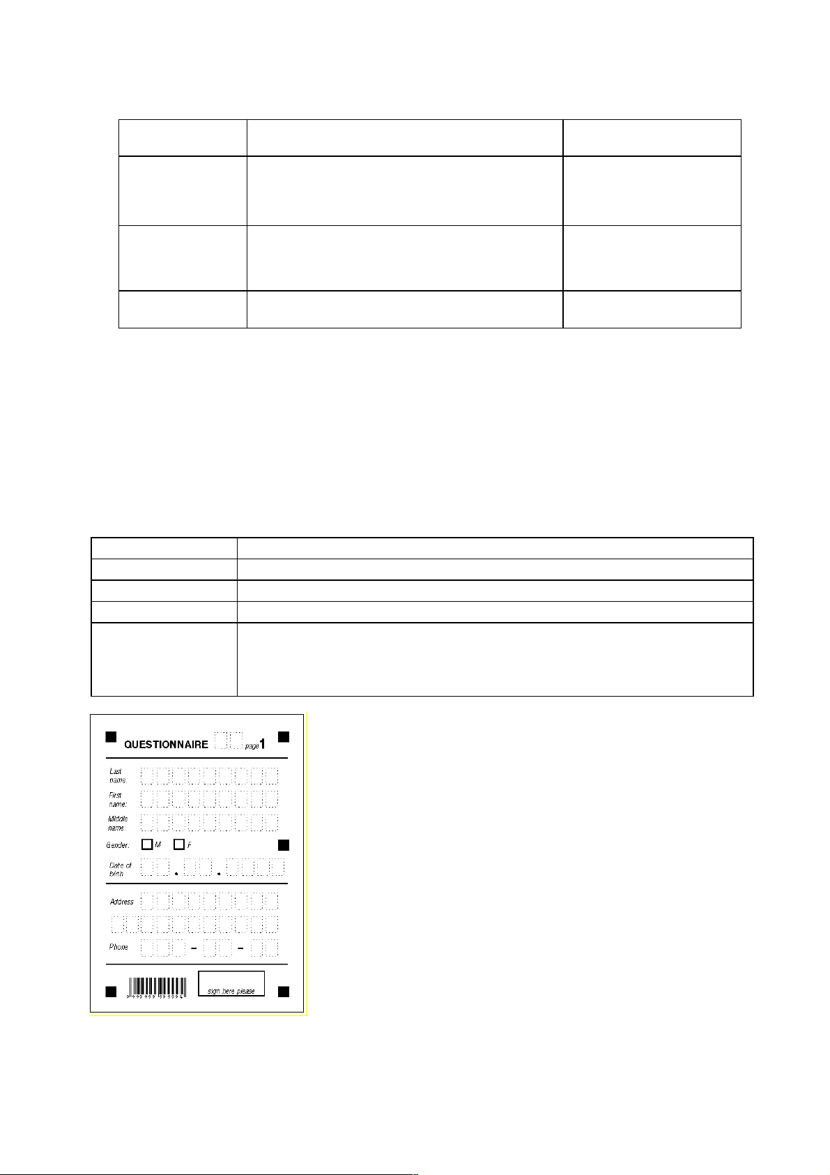
Fig. 1. An example of a blank form containing all types of reference points.
Types of machine-readable forms
There are three different form types depending on the method of separating the field contents from the field
borders:
Page 7
1. Dropout form
All the fields on the form are white rectangles on a color background. The important thing here is the color
used, as it disappears during the scanning process (see recommendations on color choice in Appendix
III), leaving only the field contents and reference points on the form image for the recognition module to
recognize.
Dropout forms are the preferred choice in terms of recognition quality.
2. Raster Forms
Field borders on raster forms are termed raster lines – i.e. lines made up of a series of dots located at equal
distance from each other. The size and the location of these dots are determined manually (see
"Black&white forms with raster backgrounds" (page 9) and "Black&white forms with raster borders" (page
9)) . These dots are retained on the image after scanning, but the system treats them as garbage and
removes them automatically during image cleaning, leaving only field contents for the recognition
module to recognize.
3. Black&white Linear Forms
Field borders in this case take on a normal appearance (i.e. are black solid lines) and remain on the image
after scanning. That means that the block image includes both field borders and field contents, and the field
contents separation task is carried out by the recognition module. Hence recognition quality will depend to
a large extent on how neatly the form was completed (see "Black&white linear forms" (Page 10).
That’s why we do not recommend the use of black&white linear forms for automated processing.
Let’s turn to the advantages and disadvantages of the following types of forms:
• dropout color forms (as well as gray forms);
• raster forms: containing raster lines as field borders and forms with raster backgrounds;
• black&white linear forms.
Dropout color forms
Dropout color forms - these are forms in which fields are represented by a series of white rectangles (or other white
geometrical shapes) on a color background. The background is usually “red-orange” or “green” in color, and
disappears if the scanner has a special driver which can filter colors (in the case of color scanners), or a colorfiltering lamp (in the case of a non-color scanners).
(a) (b)
Ideally, all form elements, with the exception of reference points, disappear during scanning, leaving only field
contents for recognition on the form image.
How is this done? By ensuring that not only the background but also the explanatory information is printed in the
dropout color (see figure (а)).
Scanning
The scanning of forms with “red” and “green” background is performed either:
a. on a color scanner with color filtering software (red or green)
b. on a non-color scanner using a red or green lamp (hardware color filtering takes place in this case).
c. on a non-color scanner using a white lamp and with a red or green filter (filtering quality in this case is
much lower, as the background may not disappear completely, or field contents may be inadvertently
removed).
Notes.
1. Many color scanners also have blue software filtering. We do not recommend the use of blue forms,
however, as forms are likely to be completed using both black and blue ink. Field contents written in blue
ink will disappear in this case.
2. Should you use a standard white lamp with no color filtering to scan your forms, various light colors (not
only “red” or “green”, but light yellow and other similar colors) are also likely to dropout. That means you
Page 8

can also use forms with such a background color with low saturation. In this case you should find the
proper color and it’s saturation manually, depending on the scanner model used.
Choosing the form color
Red-orange colors are preferable to green as a form color. This is because it represents the greatest possible contrast
to blue, and consequently results in enhanced scanning and recognition quality if the forms are completed using blue
ink.
Appendix III lists the recommended colors for form processing i.e. those most likely to disappear during scanning
with almost any scanner.. A “dropout” color list for a particular scanner (in Pantone or any other format) can also be
obtained from your scanner manufacturer/dealer.
It is up to you which color you choose, however, keep in mind that the form color chosen should be pleasant for
those required to complete it.
Advantages and disadvantages
Advantages
Drawing field borders on a color background form results in the highest possible recognition quality because:
1. Only the text image is subject to recognition; all garbage and field borders are removed.
2. Letters/digits overlapping field borders is less of a problem, as the borders themselves are simply
backgrounds which drop out during scanning, leaving only the field contents for recognition.
3. Printing explanatory information in the same color as the background increases recognition quality, as the
information “drops out” from the form image during scanning, and, consequently, does not interfere with
field contents.
4. Printing explanatory information in the same color as the background saves disk space, as the form image
file is smaller; and form processing speed increases.
Disadvantages
1. Creating a color form is complicated. A graphics editor is needed, and color forms have to be printed either
professionally or by using a color Xerox machine. Note that Xerox machines do not guarantee identical
field locations nor can black/color levels be altered.
2. Printing explanatory information in the same color as the form background reduces form readability
significantly, as the contrast between background and explanatory text is poor. This can lead to incorrect
form completion.
Gray forms
Gray forms are a subclass of color dropout forms. Gray forms are those with a shade of gray as a background color,
which again disappears during scanning. A gray background is achieved by printing the field borders in black using
the following parameters:
• saturation of no more than 10%,
• RGB parameters of 222,221,221
The resulting color is light gray due to low color saturation (i.e. black dots are rarefied).
Both field border variants depicted below may be used:
(a) (b)
Scanning
Forms may be scanned using any white lamp scanner. However, in order for the background to drop out, the correct
scanning parameters (contrast and brightness) must be chosen. If the brightness is very low and the contrast is very
high, the gray background may still remain on the image after scanning. The scanning parameters must be set
individually for each scanner.
Advantages and disadvantages
Advantages
1. The forms are very easy to develop using any graphics editor or word processing application e.g. MS
Word. See: "Developing forms using Microsoft Word" (Page 22).
Disadvantages
1. Scanning parameters (brightness and contrast) can only be altered to a slight degree. This can prove
problematic when scanning forms completed using a very light ink, as decreasing brightness to increase
Page 9
text image quality can result in the appearance of field borders or the background on the form image, and
consequently, cause a deterioration in the recognition quality.
2. If the printer makes unauthorized changes to the technical print parameters (i.e. different paper, other color
components) then the background may become too dark and could prove difficult to remove regardless of
the scanning parameters chosen.
Black&white forms with raster background
Fields on such forms are simply white spaces (usually rectangles) on a raster background. The background is made
up of individual dots, no more than 0.1 mm in size, with the distance between each dot about 1 mm. This is much
greater than is the case with gray forms, where dot density is such that the eye perceives the background as smooth
gray.
Background filtering
The raster background does not disappear during scanning itself; instead, the raster dots are classified as garbage and
removed from the image during despeckling.
Advantages and disadvantages
Advantages
Disadvantages
Black&white forms with raster borders
Field borders here are made up of raster lines i.e. sequences of small black dots. Raster dot size should be 0.39 –
0.5 pt.
1. If both the scanning parameters and the dot size are chosen correctly, the form image will be despeckled
and the recognition module will acquire the field image free of garbage and superfluous characters.
2. Letters/digits overlapping field borders is less of a problem; field borders are part of the background, and
therefore disappear during image cleaning, leaving only the field contents left to be recognized..
1. Raster forms require periods, commas and other small characters to be written thickly. This is because their
size must be greater than that of the raster dots; otherwise they will be removed as part of the background.
2. Scanning parameters (brightness and contrast) can only be altered to a limited extent. This can prove
problematic when scanning forms completed using a very light ink, as decreasing the brightness to increase
the text image quality can result in the field borders or the background appearing on the form image, and
consequently, worsen the recognition quality.
3. Not all graphic editors and word processors (e.g. MS Word) have the shading style described above (i.e.
raster) in their standard styles palette. , In addition, word processors normally only have a limited number
of raster set up tools, leading to difficulties, for example, when trying to change the distance between raster
dots, or their size.
4. A raster background can prove tiring to the eye, and consequently discourage form completion.
5. If printing density is increased, dots may become larger and, as a result, left on the image as garbage. This,
in turn can make character recognition impossible.
The recommended raster dot size is 0.39 pt, with the distance between the raster dots being at least five times larger
than the dot size:
If the distance is less, the dots may become glued during scanning, leading to them remaining on the image after
despeckling. This, in turn, leads to lower recognition quality.
Acceptable ways of completing fields with raster borders are shown in the figures below:
Page 10

(a) (b)
The advantages and disadvantages of raster field borders are the same as for raster background.
Black&white linear forms
Field borders, in the case of linear black&white forms, remain on the scanned image. This means that during
recognition the application has to first separate the field borders from the field contents, then recognize the content.
The following field border marking types are available on machine-readable forms:
Field marking type Name
Text above line
Text in a frame
Letters in separate frames
Letters in frames
Text in a comb-notch
Text in a frame with comb-notch
Advantages and disadvantages
Advantages
Disadvantages
Each one of the field marking types mentioned above has in addition a number of its own advantages and
disadvantages. These are described below:
1) Text above line
The major disadvantage of this field border type is that it does not “discipline” the person completing the form i.e.
he is free to write as he wishes. The system, however, can only recognize characters written separately (fig.(а)
below), and joined-up writing (fig.(b)) is likely to result in low recognition quality.
2) Text in a frame
The same disadvantages apply to this border type as to the previous one, however the presence of an enclosing
frame indicates the area in which information should be entered (vertical and horizontal borders) – and this is the
only advantage of this marking type.
Good recognition quality can again only be achieved if the fields are completed using separate characters, and not
touching the borders (see fig. (a) below). If this is not the case (for example, as on fig.(b) below), recognition quality
will be adversely affected.
1. The forms are very easy to design; various graphic editors and word processors can be used to create them,
including Microsoft Visio, Corel Draw, and Microsoft Word.
1. If the forms are completed carelessly, letters may overlap the field borders, thus reducing recognition
quality. This is because whenever the field content overlaps the field borders, it is extremely difficult for
the application to separate the borders from the text. Recognition quality is therefore highly dependent on
neat completion of the form.
(a) (b)
Page 11

(a) (b)
3) Letters in separate frames
This marking type is relatively effective in “disciplining” those completing the form, and the likelihood of glued
letters is low. But, as in the two previous cases, any character overlapping the borders (see fig.(b) below), is likely
to result in the disappearance of some character parts when the application separates the field borders from its
contents, thereby lowering recognition quality. For good recognition quality to be achieved, forms must be filled in
as in figure (a) below:
(a) (b)
4) Letters in frames
This marking type allows you to economize on space, but, unfortunately, allows those completing the form too much
freedom. This is because frames placed next to each other allow the use of own handwriting and, consequently,
joined-up letters. Moreover, as in previous cases, characters which overlap the borders (as in figure (b) below), can
result in certain characters not being recognized, thereby lowering recognition quality. For good recognition quality
to be achieved, forms must be filled in as in (a) below:
(a) (b)
5) Text in a comb-notch
The number of recognition errors due to character overlap is in this case lower, however, letters still need to be
written separately (see fig. (a)), and their height should be higher than the notch height.
The absence of strict borders between character spaces often leads those completing the form to use glued letters
(see figure (b) below), and in addition, no upper border is indicated, with the result that the letters can be of any
height.. In particular, the use of very small letters may result in the notches themselves being recognized as the digit
“1”, and included as part of the text.
Good recognition quality can only be achieved if a form is completed as in figure (a). Any deviation from this
pattern will result in a significant reduction in the recognition quality.
(a) (b)
6) Text in a frame with comb-notches
The same advantages and disadvantages apply to this marking type as to number 5. However, an additional
advantage is that the frame indicates ideal character height, and the area in which text should be entered. Again,
good recognition quality will only be achieved if a form is completed as in figure (a) below. Any deviation from this
pattern will result in a significant reduction in the recognition quality.
(a) (b)
How to choose a form type
Besides the advantages and disadvantages of each form type listed above, other criteria also need to be taken into
consideration when choosing a form type e.g. the required degree of recognition accuracy, form processing speed,
the scanning equipment available, printing costs and methods, and the editors to be used for form creation.
Criteria for choosing the form type
Hardware
If you have a scanner with a red or a green lamp, or a color scanner with green/red software color filtering, we
recommend the use of color dropout forms. As already mentioned, the form layout completely disappears from
such forms after scanning, together with any explanatory information (completely or partially, depending on the
form design).
By using color dropout forms:
Page 12

• the highest possible recognition quality is achieved;
• form processing is faster as there is usually no need to “clean” the form after scanning;
• the requirements for the location of explanatory information are less strict (information may be placed next to
fields or even in field boxes themselves.) This naturally makes additional form space available.
The form type you choose not only depends on the scanner you use, but also on the way you print your forms (either
using a professional printing house or an office printer). Editing costs are also likely to vary considerably depending
on the printing method chosen.
Volume, printing method, and form printing cost
If you intend to use your form in-house or the number of forms to be printed is not very large, you may wish to
choose to have a black&white raster form or a form with raster field borders.
A black&white raster form:
• will provide you with a reasonable level of recognition quality (higher than in the case of black&white linear
forms);
• may be printed using your office printer (i.e. printing costs are low).
If a large number of forms are to be processed, both black&white raster forms and dropout forms may be used. In
this case, however, we recommend that the forms be printed professionally, thus ensuring that all the technical
requirements for form printing (see: “Print quality requirements“, page 15) are met. This is particularly important in
the case of dropout forms, as the average color printer is unable to provide the necessary color quality, resulting in
the appearance of garbage after scanning and lower recognition quality.
Keep in mind that the cost of printing a color form professionally is higher than in the case of a black&white form.
However, if the volumes are sufficient, the expenditure will prove worthwhile. This is because the quality of
recognition in the case of dropout forms is significantly higher, and hence the reason why, for example, both the
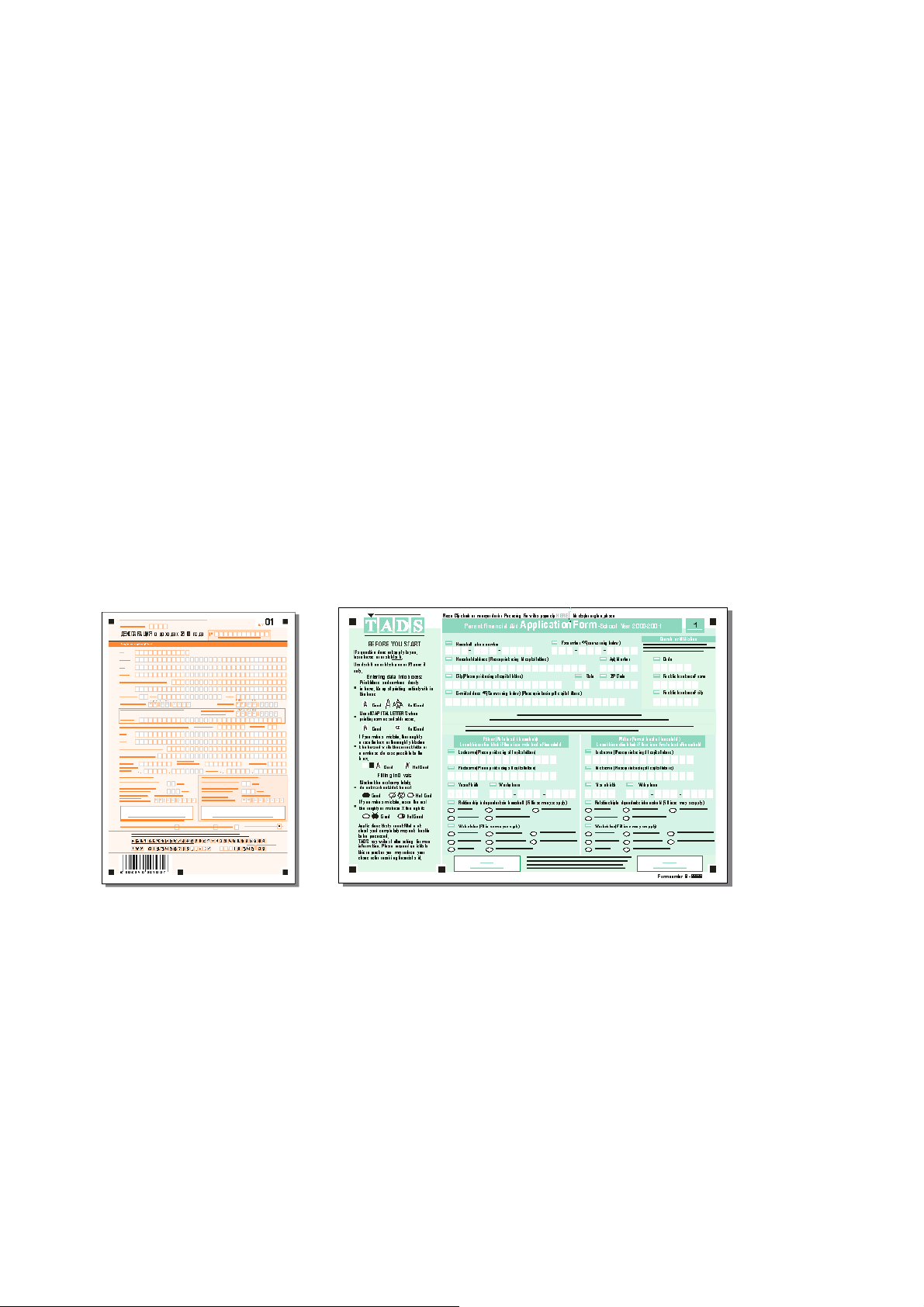
Russian State Tax Service and the Russian State Pension Fund use “orange” and “red” color background forms (see
below):
(a) “Orange” tax return forms (b) “Red” pension forms
Image size and average form processing speed
Keep in mind that for forms with the same number of fields
• the image size in the case of a black&white form will be greater than in the case of a dropout form,
• the average dropout form processing speed is higher in the case of a black&white form, as there is no need for
despeckling before recognition.
Editors for form creation
As already mentioned, not every word processor or graphics editor features an extensive range of tools for form
creation. Sometimes a black&white form will be the only type of form, which can be created, and the limitations,
which apply to its use, simply accepted.
Note. Before making a final decision regarding form type, try to take into consideration more than just the
straightforward cost or technical aspects of the form to be created. Just as important are the scale of the
projects/contracts to be undertaken, the company image, and any standard document layout style normally used by
the company.
Table: Summary of form types - advantages and disadvantages
The table below summarizes the advantages and disadvantages of each form type:
Criteria Dropout forms Black&white raster forms
Page 13

Advantage Disadvantage Advantage Disadvantage
Design Complexity
Printing
Printing Cost
Image Size
Scanning Mode
Processing Speed
Recognition Quality
Location of
Explanatory
Information
Form Appearance
Easy to design
using any graphics
editor
Difficult to print
Professional
Image file sizes are
smaller
Only special
Higher average
processing speed
Very high
recognition quality
Explanatory
information may be
placed anywhere,
including inside
fields (as long it is
printed using the
same color as the
form background)
Aesthetically
pleasing
Graphics editors
feature a good
range of tools
Easy to print inlarge quantities of
good quality forms
in-house
printing involves
higher costs
Image file sizes are
scanning modes
(color filtering)
may be used
Lower average
High recognition
Strict requirements
Less eye-catching
house
If professional
printing services
are used, printing
costs are lower
Any scanning
mode may be used
quality
Cannot be created
using all word
processors
larger
processing speed is
lower due to the
time spent on
image despeckling
as to location of
explanatory
information and to
location of other
form elements
design
Page 14

General requirements for machine-readable forms
This section summarizes the requirements for machine-readable forms.
Form background requirements
To ensure the successful separation of field contents and field borders:
1. Choose the form type best suited to your needs according to the recommendations listed above. . If
possible, use dropout forms or raster border forms (see “Table: Form Type Advantages and Disadvantages
– Summary”, page 12). The use of linear black&white forms should be avoided if at all possible.
2. Use a color that vanishes during scanning when creating a dropout form. See the list of recommended
colors in Appendix III or ask for a list of “dropout” colors from your scanner manufacturer or dealer.
3. Always ensure that a distance exists between the explanatory/service information and the field contents. In
the case of dropout forms we recommend that any information be printed in the same color as the form
background (except where static text is used as a reference point instead of or in conjunction with black
squares). By printing information in the same color as the background, you are then free to place it
anywhere on the form, including inside the form fields.
Reference point requirements
To facilitate the location of fields on the form image, a form must have special reference blocks present on it (see
“Elements of machine-readable forms“, page 6). Always ensure that the following requirements are met when
placing reference blocks on a form:
1. Both the number and location of reference blocks must be chosen to allow “reliable template matching” to take
place. We recommend that the following combinations of reference blocks be used:
a. 5 black squares, or
b. 2 vertical lines + 2 horizontal lines, or
c. 4 “static text” type blocks, or
d. 4 black squares and a barcode.
Note. Other reference blocks combinations may be used as well, e.g. 4 black squares and one “static text” block.
However, note that an excessive number of reference blocks will slow down the processing speed.
2. The distance between the edge of a reference point and the nearest form element (a text field, line, picture etc.)
should not be less than 3 mm.
3. The distance between a reference point and the edge of the page should not be less than 8 mm.
4. Reference blocks should be printed using a dark color (black is recommended) so that they do not disappear
during scanning.
5. Several reference points (we recommend using four, one in each corner) should be placed on the form to create
an imaginary closed circuit if you were to join the reference points with an imaginary line. Additional reference
points may be placed inside this imaginary shape to help differentiate different form types. But the important
point is that the all the fields to be completed must be inside this shape otherwise the application will not be able
to compensate for skew and distortion for the fields outside it.
In addition to the general requirements listed above, each reference point type has its own specific requirements:
Requirements for black squares
1. Black squares on the same form type should all be of the same size i.e. between 4х4 mm and 7х7 mm. The
recommended size is 5х5 mm.
2. Black squares must be SQUARES – black rectangles are not permitted!
3. The optimum number of squares is 5 i.e. a square in each corner (creating a rectangle) and one located on the
side of this imaginary rectangle.
Requirements for static text
1. The font size must not be less than 7 pt (headers – no less than 14 pt).
Requirements for lines
1. Line thickness should not be less than 1 pt. The recommended thickness is 1-1.5 pt.
Requirements for barcode
1. The barcode width (the distance between left and right strips of it) must not be less than 47-50mm
2. The barcode height should not be less than 12-15mm (without digits being part of barcode).
3. The barcode orientation (strips’ direction) should be the same as page orientation (and it is recommended to
scan the pages in barcode strip direction).
Notes.
1. It is recommended to use the EAN 13 barcode format
2. The recommended distance between barcode and any other form object is no less than 10mm.
Page 15

Requirements for geometric field parameters
Raster dot size
If the field borders are raster dots, the thickness of the raster line (i.e. the raster size) must be 0.4 pt. The optimal
distance between the raster dots is five times their size. However, if you have an editor that does not allow you to
specify the distance between each raster dot, you must choose a line style which has dots located at sufficient
distance from each other to prevent them from becoming glued together on the scanned image, and from remaining
on the image after image despeckling, as big dots are not interpreted by the OCR system as garbage and are not
cleaned from the image during despeckling.
Note. The dots most liable to be glued together are character space corner dots.
Character space size
The recommended size of character space is 4 х 5 mm; the use of smaller sizes requires a greater degree of accuracy
from those completing the form, and this is very difficult to achieve. Large character spaces are also not advisable as
this encourages the use of abnormally large letters. Ideally the character space size should reflect the average letter
size.
The distance between field lines should be no less than 2.5 – 3 mm, and the distance between two adjacent character
spaces in the same line no less than 1-1.2 mm.
These requirements apply to all form types.
Line thickness
If the borders are black lines (“underlined text”, “text in a frame”, “letters in separate frames” or “letters in frames”),
the line thickness should be 1 pt.
If the borders are comb-notches or frames with comb-notches, the thickness of both the notches and frame should
also be 1 pt. The recommended distance between the notches in a single form field is 5 mm. In the case of a simple
comb-notch, the distance between two lines with notches should be no less than 7.5 – 8 mm, with notch height
around 0.9 – 1.2 mm. If a frame with comb-notches is used, the minimum distance between field lines should be 2.5
- 3 mm.
Print quality requirements
When you print blank forms, keep in mind the following requirements:
1. The forms must be printed either professionally or using a printer. We recommend that color forms be printed
professionally. If this is impossible, test the form color on a scanner before starting your print run.
2. All the copies of the form must be printed using the same source document, as the field location on each form
must be identical.
3. The minimum margin size (i.e. the distance between the edge of the page and the nearest form element) should
be at least 8 mm (12 mm margins are recommended).
4. The permitted linear deviation of form elements must be no more than 0.15% ( i.e. 0.5 mm for an А4-size
page).
Page 16

5. If you print your forms using a printer, do not print them with a resolution less than 600 dpi.
6. Always use the same printer to print each form. If this is not possible, try to ensure that the same printer models
are used.
7. Never use a Xerox machine to make copies of your form! Xerox copies always distort the image to some
extent i.e. frames can become thicker, raster dot size may increase, color saturation may change. This naturally
has an adverse effect on the recognition quality as well as the ability to match the templates.
Requirements for form completion
Forms are best completed neatly, in capital letters, using a black ball-point pen (dark blue and violet are also
acceptable). Soft-tip pens are not to be recommended as characters are likely to be very thick, causing recognition
problems. Recognition is worst in the case of forms completed by pencil or using a light ink. To encourage correct
completion, we recommend to include a note on your form similar to the one below:
Creating machine-readable forms
Form creation stages
Machine-readable form creation is made up of the following stages:
1. Definition of the form content; form approval; and draft form creation.
We recommend that the form content be determined before the actual form design process is started.
2. Choice of form type (see “Types of machine-readable forms“, page 6 and “How to choose a form type,
page 11).
3. Placing the various form elements on the form (see “Elements of machine-readable forms“, page 6)
a. Placing reference blocks on the form
b. Placing entry fields on the form
During form creation, always abide by the requirements listed under “General requirements for machine-readable
forms“, page 14.
In the following two sections, the process of machine-readable form creation within Microsoft Visio 2000 and
Microsoft Word 2000 is discussed in detail.
Both packages are ideal for creating forms you are going to use print in your office: with printer or a Xerox
machine.
If you plan to use dropout forms and have them professionally printed, you will need to perform color separation
before handing over the source document to the printing house. In this case we recommend to useCorelDraw as a
graphic editor for form creation, as it has built-in color separation tools.
Note. You may also prepare a form created in MS Visio for professional printing (see "Preparing an MS Visio form
for professional printing " chapter, page 21).
Developing forms in Microsoft Visio 2000
(For the purposes of this guide we assume you already have a working knowledge of MS Visio 2000. If this is not the
case, please consult the extensive literature, which is available concerning the application.)
In order to facilitate form creation within MS Visio, a set of MS Visio stencils is included in the ABBYY
FormReader package (stored in the Elements.vss file). These allow you to determine the appearance of all main
form elements, including reference points, background colors, background patterns, and field borders.
The stencil list includes only those elements that can enhance recognition quality:
• “raster” type (for creating black&white, and red forms),
• “white rectangles on gray background” type (these are used for the creation of black&white form with 10%
black saturation, and for orange forms).
The Elements.vss file (in VisioStencils format) can be found on the ABBYY FormReader CD-Rom.
Attaching a stencil set
Before the set of stencils provided in the Elements.vss file can be used, it must be incorporated into MS Visio. This
can be done in one of two ways:
• Copy the Elements.vss file into a folder on your computer and open it in MS Visio (File>Open).
Page 17

• Open the Solutions folder located in the folder containing MS Visio in (the default location is C:\Program
Files\Visio\). Create a new folder in the Solutions folder and give it a name e.g. ABBYY Forms. Copy the
Elements.vss file into this folder.
The stencil file will be automatically incorporated into MS Visio i.e. it will be included in the list of available
stencils (MS Visio (Stencil)). To open the file, select the File>Stencil menu item and then click on the folder
created.
The form elements provided by the stencil
Once you’ve incorporated the set of stencils into MS Visio and selected the Elements item, a list of the most popular
form elements will appear on the screen (the location of the elements window and its appearance can be altered by
clicking the respective icon in the main MS Visio window toolbar):
The following form elements can be included on a form using the Elements stencil:
1. Field (Black Raster) – a standard one-line raster field with a raster size of 0.39 pt; raster color - black (100%).
To increase (decrease) the number of rectangles (character spaces in the field), place the element onto the form
(drag&drop) and drag the element’s left or right border to the left or right respectively. If you click on an element
corner, both the horizontal and vertical character space size will be adjusted simultaneously.
2. Field (Orange Raster) - a standard raster field with a raster size of 0.39 pt; raster color - orange (Pantone 164
CV 100%, represented in MS Visio by RGB: R = 252, G = 127, B = 64).
To increase (decrease) the number of rectangles (character spaces in a field), place the element onto the form
(drag&drop) and drag the element’s left or right border to the left or right respectively. If you click on an element
corner, both the horizontal and vertical character space size will be adjusted simultaneously.
Notes.
1) The maximum number of character spaces in a raster field line is 40.
2) The fill color can be easily changed in MS Visio. Simply specify the new RGB value (for more
information, see Appendix III).
3. Field (White Rectangle) – a standard field made up of white rectangles minus a color frame. Used to create
character spaces on color forms, as well as on gray forms with 10% black color saturation.
To increase (decrease) the number of rectangles (character spaces in a field), place the element onto the form
(drag&drop) and drag the element’s left or right border to the left or right respectively. If you click on an element
corner, both horizontal and vertical character space size will be adjusted simultaneously.
Notes.
Page 18

1) The default character space size for raster fields (Field (Black Raster) and Field (Orange Raster)) in the
Elements stencil is 4х5 mm and 5х6.5 mm for Field (White Rectangle).
2) Character space size for all the above field types may be altered. Field proportions are automatically
retained, thus ensuring that corner raster dots do not get glued together. Even though the character space
size may be easily changed we do not recommend making them smaller than 4х5 mm.
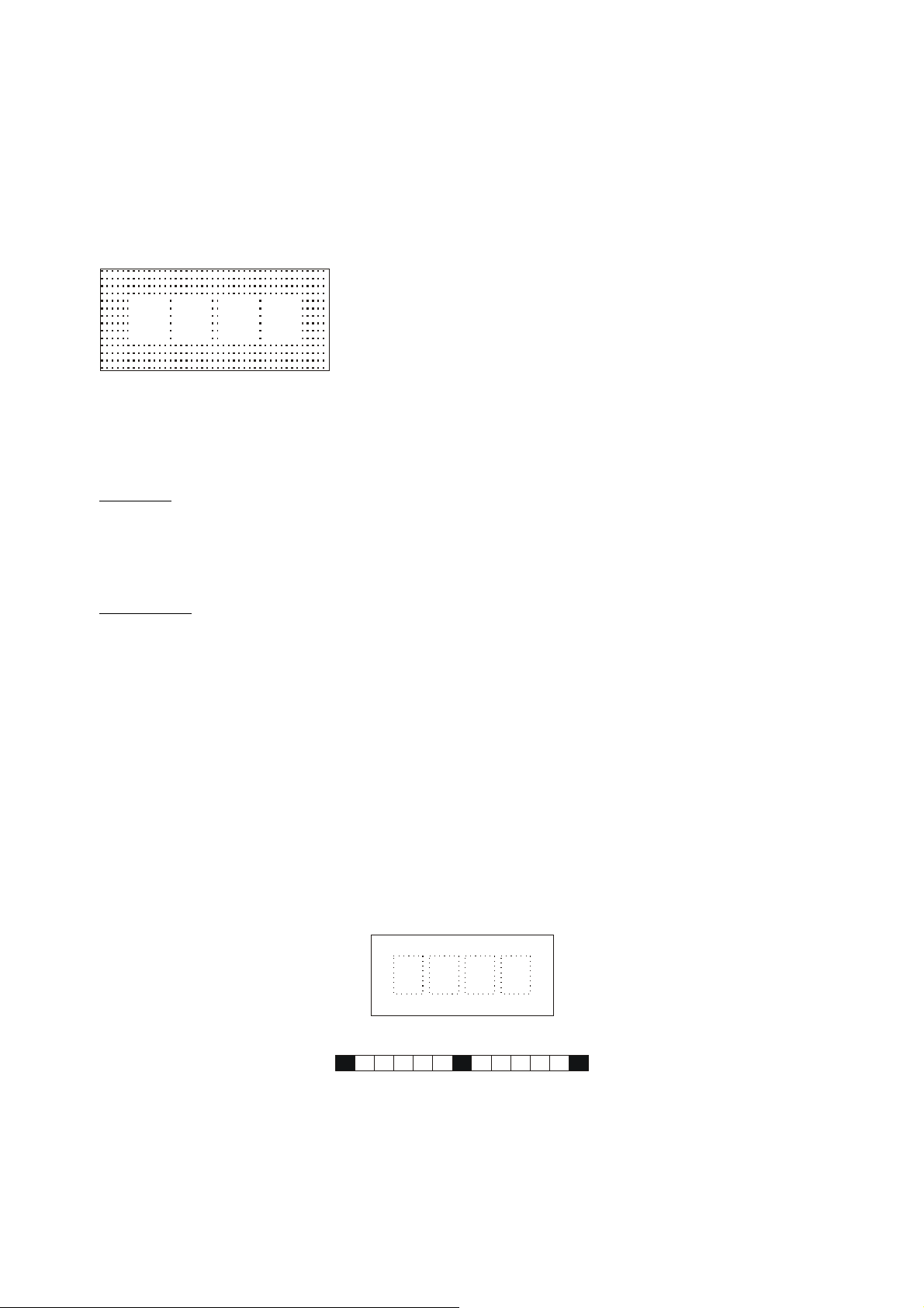
4. Date (Black Raster) – a standard date raster field. The raster size is 0,39 pt and raster color - black (100%). The
field contains enough character spaces for entering dates in digit-format i.e. Day-Month-Year (DD. MM . YYYY).
This format is best for form processing, however, you can change it if you wish, and even save it as a new stencil if
you plan to use it often.
5. Date (Orange Raster) – a standard date raster field. The raster size is 0,39 pt, and raster color - orange (Pantone
164 CV 100%, represented in MS Visio by RGB: R = 252, G = 127, B = 64). The field contains enough character
spaces for entering the date in digit-format i.e. Day-Month-Year format (DD. MM . YYYY).
6. Date (White Rectangle) - a standard field made up from white rectangles minus a color frame. Used to create
character spaces on color forms, as well as on gray forms with 10% black color saturation. The field contains
enough character spaces for entering the date in digit-format i.e. Day-Month-Year (DD. MM . YYYY).
7. Background (Gray) – a background rectangular fill element. Its horizontal and vertical dimensions may be
changed. It uses a 10% black color saturation background fill (i.e. the fill used for creating gray forms).
8. Background (Orange) - a background rectangular fill element. The horizontal and vertical dimensions may be
changed. It uses a 10% orange color saturation (Pantone 164 CV 100%, modeled in MS Visio by RGB: R = 255, G
= 243, B = 236). Used to create an “orange” form.
9. Text (Orange) – a text element with easily modifiable parameters (type, font, font size). It uses a 100% orange
color saturation fill (Pantone 164 CV 100%, modeled in MS Visio by RGB: R = 252, G = 127, B = 64), and is used
to insert explanatory information onto orange forms.
10. Text (Black) - a text element with easily modifiable parameters (type, font, font size). It uses a 100% black color
saturation fill, and may be used to insert explanatory information onto any black&white as well as color/gray form.
11. Black Square (5 x5 mm) – non-editable reference block of “black square” type. The minimum recommended
number of black squares on any form is 4 (5 if different form types are to be processed simultaneously).
Note. For the same form the squares must all be of the same size. The Elements stencil provides a non-editable
standard square, 5 х 5 mm in size.
12. Black Square + Background – same as 12), only “cushioned” by a white square. Used on gray/color forms.
13. Black Square – an editable reference block of “black square” type. Size is alterable.
14. Vertical Line 0.5 pt – “black vertical line” type block, 0.5 pt thick.
15. Horizontal Line – “black horizontal line” type block, 0.5 pt thick.
Changing field sizeTo establish the current character space size:
Right-click any character space within any form field. Select
View\Size&Position from the local menu.
The field size is denoted by two parameters: Height and Width.
To change the units of measurement:
Select the Tools\Options\Regional Settings menu item and select the
“Millimeters” item in the Pages field.
To change the size of all field character spaces (e.g. to 4х5 mm):
1. Right-click and highlight the entire field.
2. Select the View\Size&Position from the local menu. Set the Height parameter to 5 mm.
Notes.
1. The width automatically becomes 4 mm (the default size for the distributed stencil).
2. This does not need to be done for each individual field. Simply do it for one field, then copy and paste it as
needed.
To copy a field:
• Right-click the field you wish to copy, and select the Duplicate item in the local menu.
Form creation in MS Visio: example
The example below shows you how to create a gray background form with 10% gray color saturation.
1. To create a new form, select the New\New Drawing item in the File menu. A Drawing window will open
containing a “blank sheet” on which you can create your form. Arrange the Drawing and Elements windows by
selecting the Tile item in the Window menu.
Page 19

2. Drag&Drop the Background (Grey) element from the Elements window; determine its size and align it with the
page using the appropriate MS Visio tools.
3. Insert black squares into each corner of the form (drag&drop them from the Elements window). The minimum
distance between a page border and a black square should be no less than 8 mm (12 mm is recommended).
If the squares are located too near the page border, just a small amount of skew (less than 5%) will result in
their exclusion from the form image.
In the case of a multipage form, at least 5 squares need to be used. The location of the 5
th
square should be
different on each form page.
If your form has a background (and in particular a “gray” background), it is better to use the “cushioned” black
squares i.e. those with a white square cushion behind them. This will prevent any garbage from coming into
contact with the black squares (a frequent problem due to the use of incorrect scanning settings).
4. With the form basis now created, you may start work on the actual design. The following requirements should
be kept in mind, however:
• Text field lines should be located no less than 2.5-3 mm away from each other. In the case of standard
character spaces (4х5 mm), the distance between each line should be 7.5 – 8 mm.
Keep in mind as well that the distance between each line for forms supposed to be filled on a typewriter is
normally 8.467 mm (if you are not going to rotate the carriage manually)
• If black&white or color forms are to retain the explanatory information on their form image, a distance of
2-3 mm should always be maintained between them and the form fields.
• The distance between the black squares and any of other form elements should be no less than 3 mm (5
mm is recommended)
Page 20

• The distance between the lines that are to retain on the form image and form fields should be no less than
2 mm.
• If you use multipage forms, we recommend that a key field be used for further page assembling. This field
should be present on every page of the form and be unique to each copy of the form concerned (it can be
either pre-printed or filled manually). Typical examples include “Form Number” field (as on “Visitor’s
Questionnaire” in the example below), “ID Number” field etc.
The form below fulfills all the requirements of a machine-readable form:
Creating your own stencils
The stencils provided with the ABBYY FormReader can also be used to create new ones of your own.
For example, if you wanted to create a color form with a green background, using the stencils provided, this could
prove difficult. However, by editing the existing stencils, you can have a stencil with a green background in no time
at all. Proceed as follows:
1. Drag&Drop the necessary elements onto the form.
2. Change the text color (Format\Text), border color (Format\Line) or fill color (Format\Fill) for each element of
the stencil. To set up the color parameters, consult Appendix III containing the RGB values for recommended
colors.
3. Use MS Visio tools to create a new stencil set and drag&drop the elements you’ve edited into the set
concerned. Save it as a stencil file (.vss). A separate vss file can be created for each individual form created
using non-standard stencils. You can even incorporate new elements into the standard stencil set
(Elements.vss). Simply open the file and edit it.
Page 21

Preparing an MS Visio form for professional printing
As already mentioned, color separation must be carried out if you plan on printing a color forms at a printing house.
Color separation, however, cannot be carried out within MS Visio itself, therefore, if you used this editor we
recommend that the form be converted to CorelDraw format and that color separation be carried out within
CorelDraw:
1. In MS Vision open the *.vsd file containing your form (File>Open).
2. Select the Save As item in the File menu and select the Computer Graphics Metafile (CGM) file format in
the File of Type field.
Notes.
1. Every single MS Visio form page must be saved as a separate *.cgm file,as MS Visio saves the
current opened page to such a file.
2. When you save a form page to CGM format, no elements should be selected on the form,
otherwise only those objects will be saved to the *.cgm file.
3. Run CorelDraw.
4. Open all the *.cgm files relating to your form in CorelDraw.
Note. If you used the ABBYY FormReader stencils to create your form, the Font Matching Results dialog
will open when you open the *. cgm files concerned. You must then specify the fonts to be used in place of
the standard stencil fonts:
5. For CMYK palette objects, transform the colors in the PANTONE palette using CorelDraw tools.
Note. To find out whether only PANTONE colors have been used on the form, open the list of used colors
in the Print Preview mode (Settings>Separations menu).
6. Once you have completed your changes, save the files to *.cdr format.
Page 22

Developing forms using Microsoft Word 2000
(For the purposes of this guide we assume you already have a working knowledge of MS Word. If this is not the
case, please consult the extensive literature, which is available with the application.)
In the absence of a graphics editor, you can also use MS Word to create your forms.
MS Word is a word processing application and as such is not really suitable for complex form design. Unlike
graphics packages, it does not feature an entire set of editing tools, and therefore, there are certain limits to the types
of form you can design using it. We recommend that MS Word be used for creating black & white forms only.
Important! When designing forms using word processing applications, it is vital that all forms be printed using the
same printer. If this is not done, the forms printed will differ from the source document, and in essence they will not
be machine-readable.
Note. In order to facilitate form creation in MS Word, a number of sample forms (located in the Forms\MS_Word
folder on the Form Reader CD) are provided, created using MS Word tools. These files contain practically all the
form elements you are likely to use. To use any of them on your form, open the file, copy the necessary element (by
MS Word tool), then open your form and paste it to it. You can change the size and colors of the elements if
necessary.
Preparing the workspace.
Before you begin to design a form, switch to Print Layout view mode (View> Print Layout), and set up
the following page options:
1. Paper size.
2. Left and right, top and bottom borders.
3. Grid.
Paper size
When you set up the Paper size, you must decide on:
the number of fields you wish to place on the form;
the printer you will use to print your forms.
Most forms are usually А4 size, however, smaller sized forms can also be used. In some cases it may be possible to
place several small-sized forms on one sheet of A4 paper, and separate them by means of cutting lines (dashed or
solid) along which the paper will be cut.
To set up the paper size select Page Setup item in the File menu.
Page margins
Black squares must be located at least 8 mm away from the edge of the paper (12 mm is recommended). The sample
form has margins of 10 mm. To set up the page margins, select Page Setup in the File menu.
Grid
“Snap to grid” mode makes it easy to align the form elements.
The grid is only used for form creation, and is never actually printed.
To select “snap to grid” mode:
1. Click the Draw button on the Drawing toolbar and select the Grid item from
the local menu. The “Drawing grid” dialog will open.
2. Set up the following parameters:
Horizontal and vertical spacing (Grid settings)
Both vertical and horizontal spacing should be set to 0.1 cm
as this setting allows you to align/position objects and character spaces
inside the field precisely, and also to set precise distances between the text
field lines.
Display gridlines on screen
This option displays the gridlines on screen. In order to display all the
gridlines, set the “Vertical every” and “Horizontal every” to “1”.
Snap to grid
This option allows you to align the form elements using the gridlines and
to position the form elements at a given distance (multiple of grid spacing) to each other.
Note. If, after you click OK, the gridlines are still not displayed on screen, try changing the Zoom of the document.
After the workspace and the grid settings are both set up, you can start creating the form.
Page 23

Which is best - background or raster?
The best recognition results in the case of black&white forms can be obtained using raster forms (see
«Black&white forms with raster borders», page 9). Unfortunately, MS Word features only the standard line styles,
and has no tools, for example, that allow the alteration of the distance between each dots etc.. Moreover, no line
style is offered that provides the proper raster dot size and distance, i.e. for the line to disappear during image
despeckling.
We therefore recommend that solid and not raster lines be used as field borders when creating form in MS Word.
The line color should either be
• gray, RGB value: R = 222, G = 221, B = 221, black color saturation no more than 10%, or
• color, RGB value selected from the list given in Appendix III
Field borders drawn according to the above specifications should disappear from the image during scanning,
resulting in high recognition accuracy.
Note. If desired, you may create a dropout form. Specify the element Fill color and Shading color by assigning
them the necessary RGB value from the list given in Appendix III.
Setting up the background.
The background is created using a rectangular graphic element (see below the list of used elements).
If no background is present, the character spaces must be indicated by means of a frame. The standard frame colors
are detailed in Appendix III, however you can also use your own colors, as long as they can be filtered out during
scanning (but in this case you should test whether this color can really be filtered by your scanner before printing
your forms in large amounts).
The background can be set up at any time during form creation, however, if set up right at the beginning (before any
fields or explanatory information is entered), it should be made transparent to make
the grid visible on the screen. Once form creation is completed, fill the background by
selecting the fill type and the frame of your choice using the permitted set of colors
detailed in Appendix III (or your own colors if filterable). If the background is set up
after all other form elements have been chosen, the rectangle serving as the
background will overlap all the existing objects. To have the objects visible again,
right-click the background and select the Send to Back in the Order local menu.
If a background is already present, all character spaces should be enclosed in a frame,
the color of which should correspond to the background color.
MS Word 2000 graphic tools used to develop machine-readable forms.
The Drawing toolbar buttons represent the easiest way to access the functions used to create form fields. If the
Drawing toolbar is invisible, select the Drawing item in the View>Toolbars menu.
The toolbar (seen here to the right) should then appear beneath the window:
The following MS Word graphic tools are used to develop forms:
1. Text Box Used to put field headers and other explanatory information on forms.
Important! We do not recommend using simple text in order to put textual information on form; use “text
blocks” instead: framed boxes containing text (line color is the same as form background color, no fill).
All text will then remain stationary during editing.
2. Rectangle Used to insert fields, check marks, black squares, and also background and blocks not subject to
recognition (e.g. those containing signatures, stamps, photos and service information etc.).
3. Line Used to insert horizontal and vertical separators onto forms. This tool can also be used to separate the day,
month, and year in the Date field.
4. Oval Blocks of this type may be used to denote stamp location etc.
5.
, and are all used to fill various geometric objects, lines (e.g. field frames and text blocks),
and text respectively.
.
.
.
.
Positioning form elements.
To insert an element (a field, a check mark, text, a line, a black square etc.) on a form, drag it from the Drawing
toolbar onto the form, and specify its parameters (text and size) and location.
To change an object’s parameters:
Page 24

1. Right-click the object. Click on Format Object in the local menu. The Format Object dialog will open.
2. Select the appropriate parameters in the dialog.
Protecting the form.
Once form design is completed and the form is approved, the form can then be protected from
accidental modifications.
To protect a form (or “document” in MS Word terminology):
1. Select the Protect Document item in the Tools menu. The Protect Document dialog will
open.
2. Select the Forms item in the dialog and click OK.
Note. If necessary, you may add password protection to the document.
To remove document protection, select Unprotect Document in the Tools menu. If the document
is password protected, you must enter the password to unprotect it.
A form can also be protected without using password protection by clicking on the Protect Form button (
the Forms toolbar. If this toolbar isn’t displayed, select the Toolbars>Forms item in the View menu:
,
Note. The Text Form Field (
to create an MS Word-compatible form. Once form protection is enabled on the form itself (and applied to field
headers, explanatory information etc.), the form cannot be edited, and only field texts and values of the Check Box
type may be altered. Switch from one field to the next by using the Tab button (top-to-bottom, left-to-right) or
Shift+Tab (to reverse order). Switch from one line to the next (up and down) by using the arrow keys.
When designing such a form, you can also specify a field entry mask (e.g. maximum field length), which will then
serve to standardize the information entered in the field. For more information on the creation of machine-readable
forms that are to be completed in MS Word, see the MS Word User’s Guide, MS Word Help, or other specialized
literature.
) and the Check Box Form Field ( ) buttons on the Forms toolbar can also be used
) on
Certification
If you plan to print a large number of form copies, we recommend you send us your source form for prior
certification. Our form design experts will then examine the form for machine-readability, and inform you of any
problems/difficulties (if any) that are likely to arise. All forms approved by us are entitled to carry the ABBYY seal
of approval:
“This form meets the machine-readability requirements of ABBYY FormReader. Certificate №
________________________”
Page 25

Appendices
Useful tips.
1. Raster forms. The raster field marking type is the most useful field marking type when it comes to black&white
forms. Not only is it easy to create, it also provides the best recognition quality for black&white forms.
Moreover, the image size is the smallest in the case of raster forms compared to all other black&white forms.
2. Red raster field marking type. Red raster represent a good alternative to black raster if the scanning mode to be
used is unknown. If a “red-lamp” scanner is used, the red raster borders will be filtered out during scanning. If a
“white-lamp” scanner is used, the raster borders become black and are removed as garbage during image
despeckling. In both cases, therefore, borders are removed.
3. Beware of double-sided forms! If a space has been allocated for a photo or stamp on a double-sided form, you
must ensure that the glue and/or stamp do not adversely affect the information printed/entered on the reverse side
(the glue can work its way through or the ink may be visible). One way this problem can be avoided is to place
explanatory or descriptive information on the reverse side of the form, directly opposite the location of the
photo/stamp.
4. Positioning the “signature” field. The signature field should always be allocated enough space to ensure that
the signature itself does not interfere with any other information entered on the form. This is best achieved by
locating the field next to the explanatory information blocks.
5. Additional verification. If it is vital that the information entered in a certain field is correct, place several fields
on the form, that contain the same information written in different ways (e.g. sum in figures – sum in words,
client name – client social security number etc.). These fields help to verify the information automatically.
6. Positioning barcode-type elements. MS Word and MS Visio feature no tools for barcode creation. However,
barcodes can be created using another package (e.g. CorelDraw) and then pasted onto a form created using MS
Visio or Word. After pasting the barcode onto the form, always ensure that the geometric parameters of the
barcode (and not the barcode object itself which contains both barcode values, digital values and borders) meet
the requirements specified above (barcode size: 47- 50 mm in width, 12-14 mm in height).
7. Simultaneous processing of different form types. If you process more than one type of form at the same time,
you must ensure that at least one unique element (a so-called control block) is placed on each form to allow
differentiation to take place. The application only makes use of control blocks when confronted with more than
one type of form. The following four are particularly useful:
Control Block Types Notes
Additional 5th black square Should be positioned on the side of a form in addition to the 4 blocks located at each corner.
Barcode
Static text Textual information. Use text blocks set in a monospaced sans serif font no less than 8 mm in height.
For more information on the use of control blocks, see Appendix I “Identification of different forms processed
in the same batch”.
We recommend that EAN 13 type barcodes be used (min. width 47- 50 mm, min. height12-14 mm).
Page 26

Identification of different forms processed in the same batch
There are certain things that must be considered during form creation:
• whether the form is to be a multipage form
• whether the form will be processed in the same batch with forms of a different type
In both cases, additional identification reference blocks are required. These elements allow the system to identify the
form type and select the proper template as well as to match it correctly (i.e. to locate fields location). The following
elements may be used:
1) Black squares
As mentioned previously, the optimal number of black squares on a form is five. Four of these squares should be
located in each corner, creating an imaginary rectangle, and the fifth on the side of this rectangle, its location
differing according to form page and form type (the fifth square being the feature that allows the application to
distinguish between different form pages and types). Note that fifth squares must differ in location by at least 10-15
mm if form identification is to be successful.
2) Barcodes
We recommend that EAN 13 barcodes 47- 50 mm in width (the distance between the barcode line furthest to the
right and the barcode line furthest to the left) and 12-14 mm in height (barcode digit heights are not included in
these measurements) be used, and that a distance of no less than 10 mm be allowed between each barcode and all
other form elements.
The barcode line direction should coincide with form page orientation, and the forms should be scanned in the same
direction as that of the barcode bars.
Barcodes located on different form pages as well as on forms of different types should always differ in value, and
only then can they be used as form identifiers.
3) Static text
The text should be clear and legible, and present no problems to an OCR system.. Static text identifiers should be
lines set in a plain monospaced font (without any stylization) and no less than 8 mm in size. We recommend a
distance of no less than 10 mm between each static text block and all other form elements. Static text lines located
on forms of different types should always differ in content, and only then they may be used as form identifiers.
Notes.
1. The number of reference points used on a form depends on the form design and the amount of free space
present on it. The presence of a large number of reference points on a form does not mean that all of them will
be used as such by the OCR system.
If the quantity of forms is to be very large (and especially if the form is to be printed professionally), we
recommend that the form be tested beforehand by printing out a copy on a printer, and creating an appropriate
template using the OCR system. Ensure that the reference points placed on the form result in both correct
template matching and deskewing (in the case of scanning defects), and correct form identification if several
types of form are present in the same batch.
If there is no possibility of testing a form before it is printed (samples of the other forms to be processed at the
same time, for example, may not be available), we recommend that two or more types of reference blocks be
used on the form concerned. As a result, a combination of reference points that provides the best form
identification can be used during template creation.
2. If a barcode or static text is to be used as a reference point, attention must be paid to their color. They must be
retained on form image after scanning, and their images must be of high quality, with no skew, garbage, or
glued bars/letters present. The recommended color for reference blocks is black.
Page 27

Creating a barcode using CorelDraw
This appendix explains how a barcode (EAN-13 format) can be created using CorelDraw. Once created, the barcode
can be saved to file and then inserted into a form, or pasted (using the “copy&paste” function) as an OLE-object into
any form of your choice, including one developed using a word processing application such as MS Word or MS
Visio.
Barcode creation is only possible if supported by the current CorelDraw installation (the Edit > Insert Barcode item
must be enabled). If this option is disabled, you must reinstall Corel Draw activating this option, and ensure that this
option is enabled.
Once the Edit > Insert Barcode item is enabled, instructions on how to proceed are given by the Barcode Wizard:
1) Select the EAN-13 item from the list of standard barcode types.
2) Enter the 12 digits of barcode, as shown on the figure (the sample barcode consists of twelve “9” digits).
The last (13
th
) digit is the CRC and is entered automatically. The barcode add-on (“Add On”) is not to be
entered.
3) Click “Next”
4) Set the “Printer resolution” to 600 dpi
5) Set up all other parameters as shown on the figure below:
6) Click on “Next”
7) Enable the “Make this bar code Human Readable (show text)” option. This option displays the barcode
digits.
8) Click on “Finish”
Page 28

9) The created barcode is displayed in the CorelDraw window. The developer must then alter the barcode size
until it complies with the requirements relating to barcodes placed on machine-readable form (see
“Requirements for barcode”, page 14)
Page 29
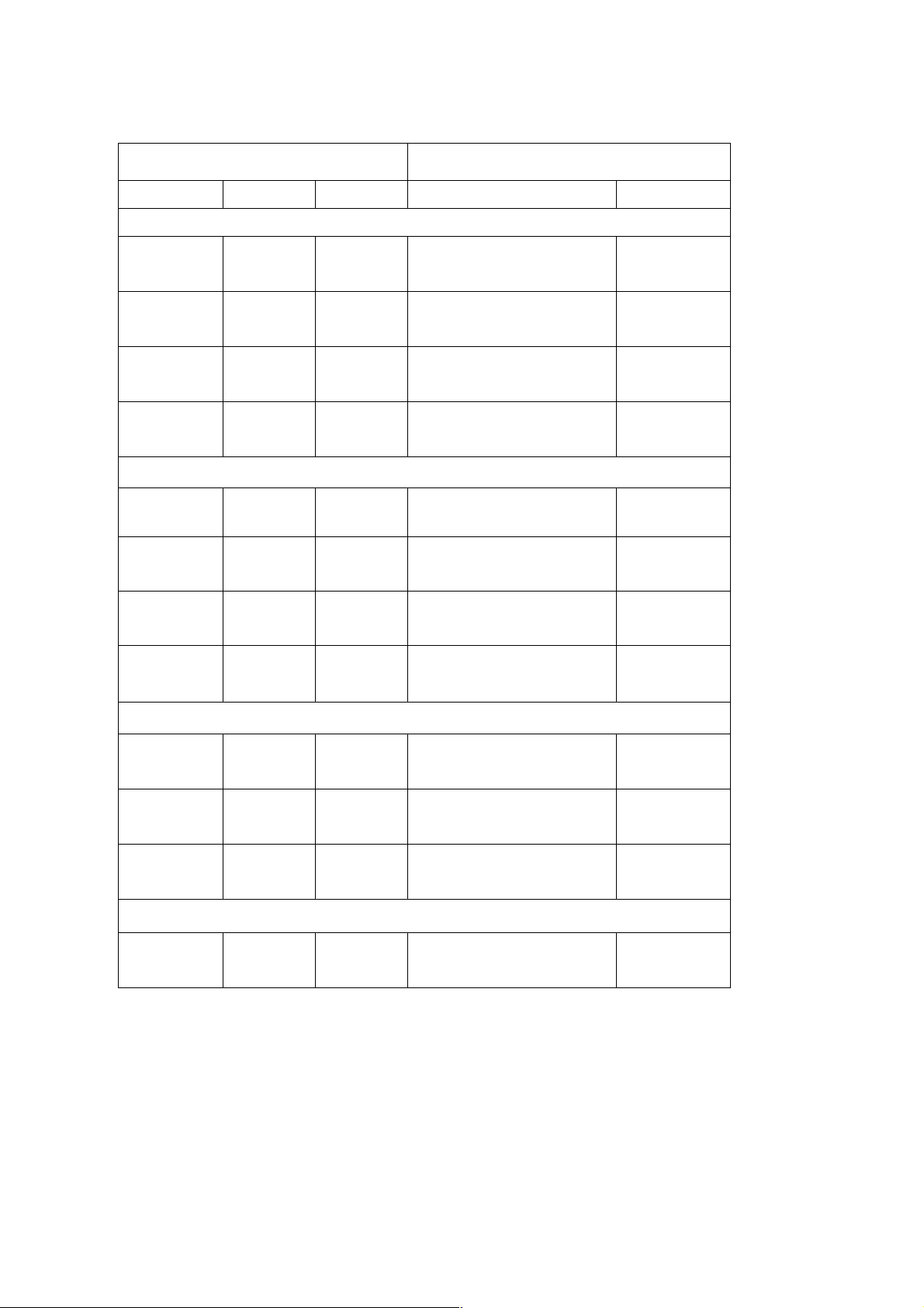
Recommended colors for dropout forms
RGB Pantone
R G B Paint Saturation
Orange Form
252 127 64 Pantone 164 CV
254 191 160 Pantone 164 CV
255 230 217 Pantone 164 CV
255 243 236 Pantone 164 CV
Red Form
250 64 37 PANTONE Warm Red CV 100%
253 160 146 PANTONE Warm Red CV 50%
254 217 212 PANTONE Warm Red CV 20%
255 240 238 PANTONE Warm Red CV 8%
100%
50%
20%
10%
Green Form
150 218 176 PANTONE 345 CV 100%
203 237 216 PANTONE 345 CV 50%
234 248 240 PANTONE 345 CV 20%
Gray Form
222 221 221
Important! You MUST use Pantone colors if you plan to have your forms professionally printed (i.e. at a printing
house).
Pantone Cool Gray 1 CV
(10% Black)
100%
 Loading...