

ABB Xiamen M2131 User manual
Warning
Single-wire clamps
2 x 0.28 mm² – 2 x 0.75 mm²;
Fine-wire clamps
2 x 0.28 mm² – 2 x 0.75 mm²;
Bus voltage
20-30V DC
Protection
IP 54
Power supply ,door
opener (Lock-GND)
18V 4A impulsive, 250mA holding
Floating output, door
opener (COM-NC-NO)
30V AC / DC 1A
Operating temperature
-40 °C – +70 °C -40 °F – 158 °F
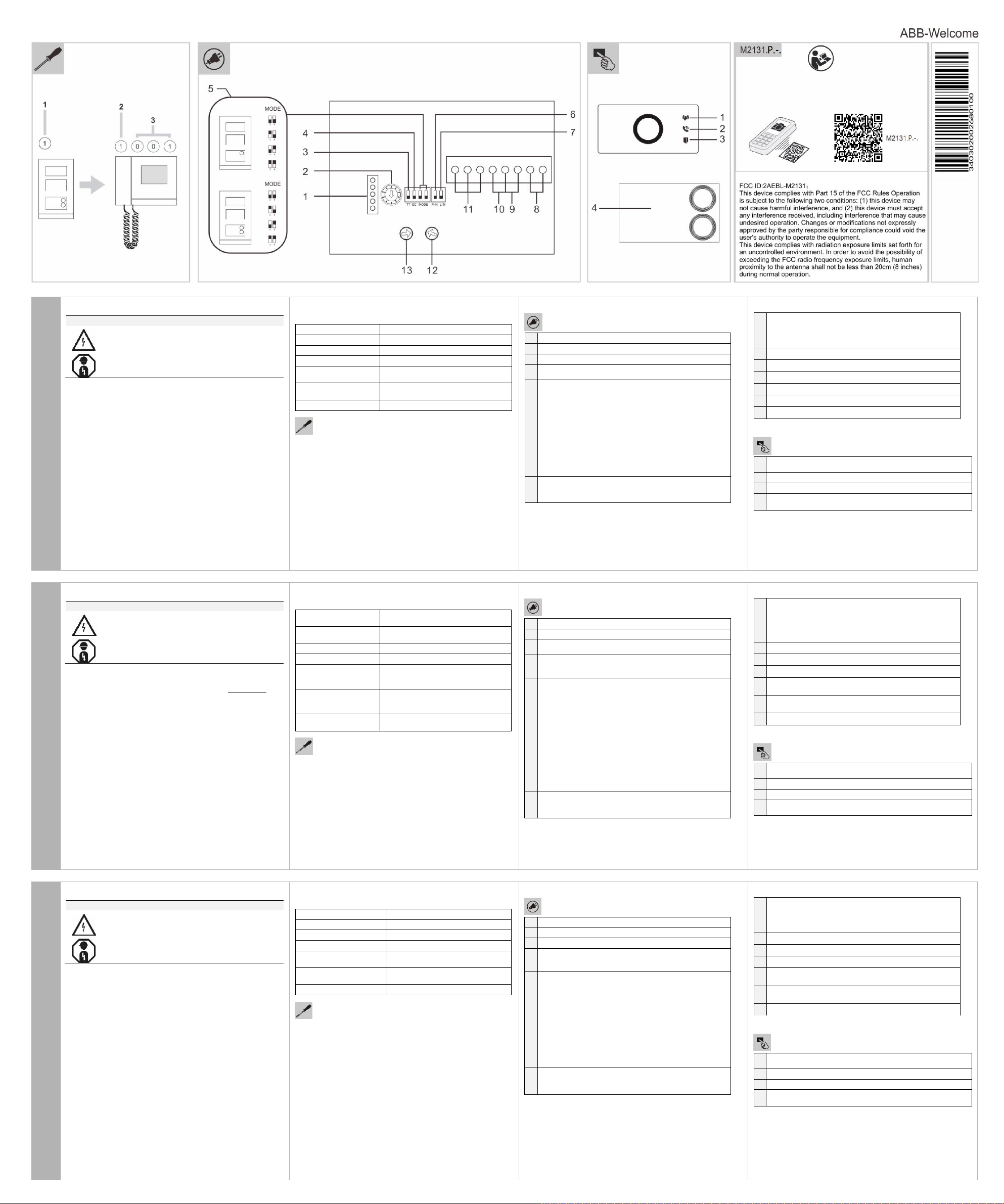
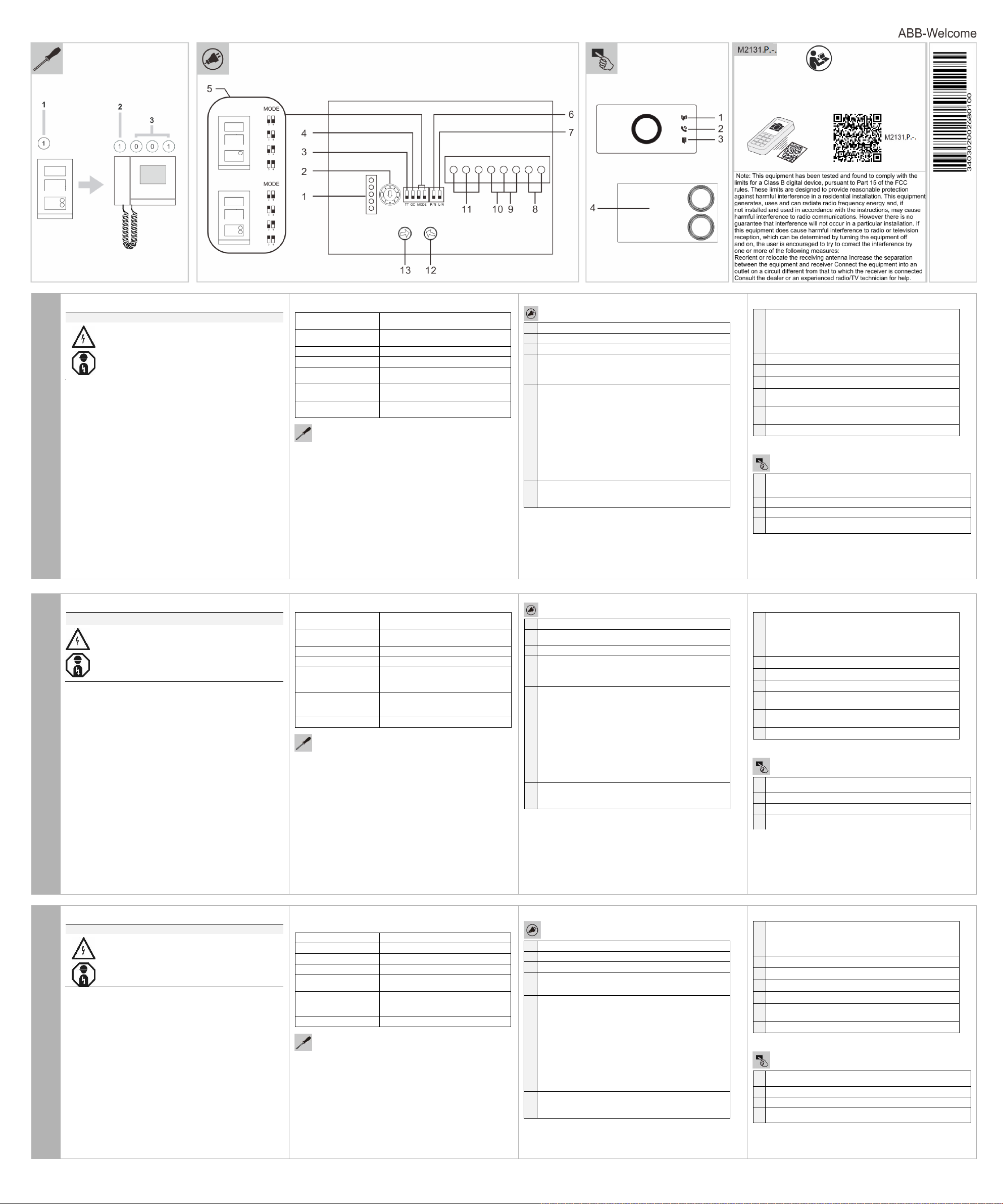
1
Connector for device software update
2
Rotary switch to set the address of OS (1-9)
3
Set feedback tone of pushbutton: ON/OFF
4
5
7
8
Plug-in clamps (a,b) for bus connection
9
Plug-in clamps (Exit-GND) for exit button
10
Plug-in clamps (Lock-GND) for door opener
11
Plug-in clamps (COM-NC-NO) for floating output, door opener
12
13
1
2
3
4
Abrazaderas de un
solo alambre
Abrazaderas alambre
fino
Tensión de bus
Protección
Fuente de alimentación, apertura de
puerta (Lock-GND)
Impulsivo 18V 4A, Retención 250mA
Salida flotante,
apertura de puerta
(COM-NC-NA)
30V CA / CD 1A
Temperatura de funcionamiento
-40 °C – +70 °C -40 °F – 158 °F
1
Conector para la actualización del software del dispositivo
2
Interruptor giratorio para ajustar la dirección del OS (1-9)
3
Ajustar el tono de retroalimentación del botón de pulsado:
ON/OFF
5
6
7
8
9
Braçadeiras plug-in (Exit-GND) para botão de saída
10
Braçadeiras plug-in (Lock-GND) para abridor de porta
11
Braçadeiras plug-in (COM-NC-NO) para saída flutuante e
abridor de porta
12
13
Interruptor rotativo para ajustar volume de coluna
1
2
LED ligado indica comunicação possível
3
LED ligado indica porta desbloqueada
4
Se o botão redondo tiver leitor de cartão ID, consulte os detalhes no
manual da estação exterior.
Avvertenza
Morsetti di cavo singolo
2 x 0.28 mm² – 2 x 0.75 mm²;
Morsetti di cavo fine
2 x 0.28 mm² – 2 x 0.75 mm²;
Tensione Bus
20-30V CC
Protezione
IP 54
Alimentazione, apertura
porta (Lock-GND)
18V 4A impulso, 250mA tenuta
Output mobile, apertura
porta (COM-NC-NO)
30V AC / CC 1A
Temperatura di esercizio
-40 °C – +70 °C -40 °F – 158 °F
1
Connettore per aggiornamento software dispositivo
2
Interrutore a rotazione per impostare l’indirizzo di OS (1-9)
3
Imposta tono di risposta di pressione pulsante: ON/OFF
4
5
6
7
8
Innesta i morsetti di (a,b) per connessione del bus
9
Innesta i morsetti (Exit-GND) per il tasto di uscita
10
Innesta i morsetti (Lock-GND) per l’apertura della porta
11
Innesta i morsetti (COM-NC-NO) per uscita mobile, apertura
porta
12
Interrutore a rotazione per regolare il tempo di rilascio del blocco
porta di default, 1-10s
13
Interrutore a rotazione per regolare il volume dell’altoparlante
1
2
LED si accende per indicare comunicazione possibile
3
LED si accende per indicare porta sbloccata
4
Se il pulsante è rotondo con lettore ID card,consultare i dettagli nel
manuale della stazione in esterni.
Mini Video Outdoor Station
Please read the mounting instructions carefully and keep them
Detailed user manual is available via the link in chapter "Service"
Intended use
The outdoor station is part of the ABB-Welcome door communication
system and operates exclusively with components from this system.
The device must only be used with suitable ABB-Welcome surface-
English
mounted installation sockets.
Mini video outdoor station has 1/2 round pushbuttons, light switch or
calling guard programmable for the button, built-in ID card reader and
up to 2 locks connections.
Risk of death and fire due to electrical voltage of 100240V.
Work on the 100-240V supply system may only be
performed by authorized electricians!
Disconnect the mains power supply prior to installa-
tion and/or disassembly!
for future use.
or by scanning the QR codes (device with corresponding software
is required).
Technical data
Addressing
For outdoor stations: With the selector switch 1 set the address of
the outdoor station (1 to 9).
For indoor stations: With the left selector switch 2 set the address
of the default outdoor station (1 to 9).
Then use the other two selector switches and dip-switches 3 to set
the address (hundreds, tens and units digits e.g. 001) of the indoor
station.
Mounting & Connection
Set general call to all indoor stations in one family: ON/OFF
If GC=ON, press button 1/button 2, all IS ring
Configuration function of 1st/2nd round pushbutton
5A Mini Video Outdoor Station with one push botton
3 -> OFF; 4 -> OFF = Call IS 001
3 -> ON; 4 -> OFF = Switch on light
3 -> OFF; 4 -> ON = Call guard unit
3 -> ON; 4 -> ON = Call IS 001
5B Mini Video Outdoor Station with two push botton
3 -> OFF; 4 -> OFF = Call IS 001/002
3 -> ON; 4 -> OFF = Switch on light/call IS 001
3 -> OFF; 4 -> ON = Call guard unit/call IS 001
3 -> ON; 4 -> ON = Call IS 001/call IS 002
Set the video mode PAL/NTSC
OFF = PAL video mode
6
ON = NTSC video mode
Set default lock
OFF = set (Lock-GND) as default lock
ON = set (COM-NC-NO) as default lock
*Default lock is controlled by "unlock" button on IS
Rotary switch to adjust default door lock release time, 1-10s
Rotary switch to adjust loudspeaker volume
Operation
LED flashed slowly to indicate call established
LED flashed fast to indicate system busy
LED illuminate to indicate communication possible
LED illuminate to indicate door unlocked
If round pushbutton with ID card reader,please find the details in
outdoor station manual.
Service
ABB Genway Xiamen Electrical Equipment CO., LTD.
http://new.abb.com/low-voltage/products/residential-products/doorcommunication
Estación al Aire Libre de Mini Video
Por favor, lea las instrucciones de montaje y guárdelas para ser
El manual de usuario puede ser descargado en www.abb.es.
Uso indicado
La estación al aire libre es parte del sistema de interfonía de ABBWelcome y funcionamiento exclusivo con componentes de este
sistema
El dispositivo sólo se debe utilizar con zócalos de instalación de
montaje en superficie de ABB-Welcome adecuados.
Español
Mini estación al aire libre de vídeo tiene 1/2 pulsadores redondos,
interruptor de iluminación o bloqueo de llamada programable para el
botón, una función de lector de tarjeta de identificación y hasta 2
conexiones cerraduras.
Advertencia
Riesgo de muerte y fuego causado por voltaje eléctrico de
100-240V
¡Sólo se permite que electricistas autorizados operan
el sistema de potencia de operación de 100-240V!
¡Desconectar la fuente de potencia principal antes de
instalación y/o desmontaje!
usadas en el futuro.
Datos Técnicos
2 x 0.28 mm² – 2 x 0.75 mm²;
2 x 0.28 mm² – 2 x 0.75 mm²;
20-30V DC
IP 54
Direccionamiento
Para las estaciones al aire libre: Con el selector 1 se establece la
dirección de la estación al aire libre (1 a 9).
Para las estaciones de interior: Con el interruptor de selección
izquierdo 2 se establece la dirección de la estación al aire libre
predeterminada (1 a 9).
A continuación, utilice los otros dos interruptores 3 para establecer la
dirección (cientos, decenas y dígitos de unidades por ejemplo, 001)
de la estación interior.
Montaje y Conexión
Ajustar la llamada general a toda la estación interior en un solo
grupo: ON/OFF
4
Si GC=ON, pulse el botón 1/botón 2, todo timbre IS
La función de configuración del primer/segundo botón de
pulsado redondo
5A Estación al aire libre de Mini Video con un botón de pulsado
3 -> OFF; 4 -> OFF = Llamada IS 001
3 -> ON; 4 -> OFF = Encender la luz
3 -> OFF; 4 -> ON = Unidad de bloqueo de llamada
3 -> ON; 4 -> ON = Llamada IS 001
5B Mini Video Estación al aire libre con dos botones pulsado
3 -> OFF; 4 -> OFF = llamada IS 001/002
3 -> ON; 4 -> OFF = Encender luz/llamada IS 001
3 -> OFF; 4 -> ON = Boqueo de llamadas unidad/llamada IS
001
3 -> ON; 4 -> ON = Llamada IS 001/llamada IS 002
Ajustar el modo de video PAL/NTSC
OFF = Modo video PAL
ON = Modo video NTSC
Definir bloqueio padrão
OFF = definir (Lock-GND) como bloqueio padrão
ON = definir (COM-NC-NO) como bloqueio padrão
* O bloqueio padrão é controlado pelo botão "unlock"
(desbloquear) no IS
Braçadeiras plug-in (a, b) para ligação bus
Interruptor rotativo para ajustar tempo de libertação de bloqueio
de porta padrão, 1-10 seg
Funcionamiento
LED a piscar devagar indica chamada estabelecida
LED a piscar rápido indica sistema ocupado
Atenciòn al Cliente
www.abb.es
Mini Stazione Video per Esterni
Si prega di leggere le istruzioni di montaggio con attenzione e
Il manuale utente dettagliato è disponibile sul sito nel capitolo
Uso conforme alle prescrizioni
La stazione in esterni è parte del sistema di porta di comunicazione
ABB-Welcome e funziona esclusivamente con componenti di tale
sistema.
Italiano
Il dispositivo deve essere utilizzato solo con prese di installazione
montate a superficie compatibili con ABB-Welcome.
La Mini stazione video per esterni ha 1/2 pulsanti rotondi, interruttore
di luce o chiamata di guardia programmabile per il tasto, lettore ID
card incorporato e fino a 2 blocchi di connessione.
Rischio di morte e di fiamme causati dalla tensione
elettrica 100-240V.
Lavorare sull'alimentazione da 100-240V solo se
elettricisti autorizzati
Scollegare la tensione di alimentazione prima di
installare o disinstallare i dispostivi.
conservarle per future consultazioni.
“Service" o utilizzando il QR code (necessario software per la
lettura)
Dati Tecnici
Programmazione
Per stazioni in esterni: con il selettore 1 impostare l’indirizzo della
stazione in esterni (da 1 a 9).
Per stazioni in interni: con il selettore 2 di sinistra impostare
l’indirizzo della stazione in esterni di default (da 1 a 9).
Usare gli altri due selettori e interruttori 3 per impostare l’indirizzo
(centinaia, decine e unità, ad es. 001) della stazione in interni.
Montaggio & Connessione
Imposta chiamata generale per tutte le stazioni in interni in una
sola famiglia: ON/OFF
Se GC=ON, premere il tasto 1/tasto 2, tutti gli IS suonano
Funzione di configurazione di 1°/2° pulsante rotondo
5A Mini Video Stazione per Esterni con un solo pulsante
3 -> OFF; 4 -> OFF = Chiama IS 001
3 -> ON; 4 -> OFF = Accende la luce
3 -> OFF; 4 -> ON = Chiama unità di guardia
3 -> ON; 4 -> ON = Chiama IS 001
5B Mini Video Stazione per Esterni con due pulsanti
3 -> OFF; 4 -> OFF = Chiama IS 001/002
3 -> ON; 4 -> OFF = Accende la luce / Chiama IS 001
3 -> OFF; 4 -> ON = Chiama unità di guardia / Chiama IS 001
3 -> ON; 4 -> ON = Chiama IS 001/ Chiama IS 002
Imposta la modalità video PAL/NTSC
OFF = modalità video PAL
ON = modalità video NTSC
Imposta blocco di default
OFF = imposta (Lock-GND) come blocco di default
ON = imposta (COM-NC-NO) come blocco di default
* Il blocco di default è controllato dal tasto "sblocca" su IS
Funzionamento
LED lampeggia lentamente per indicare chiamata stabilita
LED lampeggia veloce per indicare che il sistema è occupato
Avertissement
Colliers de serrage à fil
unique
2 x 0,28 mm² – 2 x 0,75 mm²;
Colliers de serrage à fil
fin
2 x 0,28 mm² – 2 x 0,75 mm²;
Tension du bus
20-30 V CC
Protection
IP 54
Alimentation, Ouvreporte (Lock-GND)
18V 4A impulsive, 250mA détenue
Sortie flottante, Ouvreporte (COM-NC-NO)
30V CA / CC 1A
Température de
fonctionnement
-40 °C – +70 °C -40 °F– 158 °F
1
Connecteur pour la mise à jour du logiciel de l'appareil
2
Commutateur rotatif pour définir l'adresse de l'OS (1-9)
3
Définir le ton de la rétroaction du bouton-poussoir: ON / OFF
4
5
6
7
8
Pinces de connexion (a, b) pour la connexion de bus
9
Pinces de connexion (Exit-GND) pour le bouton de sortie
10
Pinces de connexion (Lock-GND) pour ouvre-porte
11
Pinces de connexion (COM-NC-NO) pour sortie flottante, ouvreporte
12
13
1
2
Le voyant LED s'allume pour indiquer une communication possible
3
Le voyant LED s'allume pour indiquer une porte déverrouillée
4
Si le bouton-poussoir rond avec lecteur de carte d'identité,veuillez
trouver les détails dans le manuel du poste extérieur.
240 V mogą
Zaciski przewodów
jednożyłowych
2 x 0,28 mm² – 2 x 0,75 mm²;
Zaciski przewodów
cienkożyłowych
Napięcie szyny
20-30V DC
Stopień ochrony
IP 54
Zasilanie, zaczep
zamka drzwi (LockGND)
Wyjście zmienne,
zaczep zamka drzwi
(COM-NC-NO)
30V AC / DC 1A
Temperatura robocza
-40 °C – +70 °C -40 °F– 158 °F
Przyłącze do aktualizacji oprogramowania urządzenia
Przełącznik obrotowy do ustawiania adresu stacji zewnętrznych
(1-9)
Przycisk ustawiania sygnału zwrotnego: ON/OFF
4
5
6
7
8
Złącza wtykowe (a,b.) do połączeń do szyny
9
10
11
Złącza wtykowe (COM-NC-NO) do zmiennego wyjścia, zaczepu
zamka
12
Przełącznik obrotowy do ustawiania domyślnego czasu
zwalniania zamka drzwi, 1-10s
13
Przełącznik obrotowy do ustawiania głośności głośnika
1
2
LED świecący się wskazuje na możliwość komunikacji
3
LED świecący się wskazuje na otwarty zamek drzwi
4
Odnośnie przycisku z czytnikiem kart ID, informacje znajdują się w
instrukcji obsługi stacji zewnętrznej.
Advarsel
Entrådede klemmer
2 x 0,28 mm² – 2 x 0,75 mm²
Fintrådede klemmer
2 x 0,28 mm² – 2 x 0,75 mm²
Busspenning
20-30V DC
Beskyttelse
IP 54
Strømforsyning,
døråpner (Lock-GND)
18V 4A rask, 250mA treg
Ujordet utgang,
døråpner (COM-NCNO)
30V AC / DC 1A
Driftstemperatur
-40 °C – +70 °C -40 °F– 158 °F
1
Tilkobling for programvareoppdatering av enheten
2
Dreiebryter for å angi adresse til OS (1-9)
3
Tone for trykknapp: PÅ/AV
4
5
6
7
8
Terminalklemmer (a,b) for bussforbindelse
9
Terminalklemmer (Exit-GND) for exit-knappen
10
Terminalklemmer (Lock-GND) for døråpner
11
Terminalklemmer (COM-NC-NO) for ujordet utgang, døråpner
12
Dreiebryter for å justere frigjøringstid for standard dørlås, 1-10
sek.
13
Dreiebryter for å justere høyttalervolumet
1
2
LED lyser for å indikere at kommunikasjon er mulig
3
LED lyser for å indikere at døren er ulåst
4
For rund trykknapp med ID-kortleser, kan du finne informasjon i
bruksanvisningen for utendørs stasjon.
Poste extérieur vidéo mini
Lisez attentivement les instructions de montage et gardez les
Une notice d'utilisation est disponible via le lien dans le chapitre
Utilisation prévue
Le poste extérieur fait partie du système de communication de porte
ABB-Welcome et fonctionne exclusivement avec les composants de
ce système.
L'appareil ne doit qu'être utilisé avec les prises d'installation montées
Français
à la surface ABB-Welcome.
Le poste extérieur vidéo mini a 1/2 boutons poussoirs ronds, un
interrupteur de lumière ou protection d'appel programmable pour le
bouton, un lecteur de carte d'identité intégré et jusqu'à 2 connexions
de verrouillage.
La tension électrique en 100-240V peut provoquer des
chocs électriques ou des incendies en cas de mauvaise
utilisation.
Le travail sous une tension de 100-240V doit être
effectué par un technicien spécialisé.
Couper le courant avant toute intervention sur le
matériel.
pour une utilisation future.
"Service" ou en scannant le QR code (avec un appareil équipé
d'un logiciel adapté).
Données techniques
Adressage
Pour les postes extérieurs: Avec le commutateur de sélection 1
définir l'adresse du poste extérieur (1 à 9).
Pour les postes intérieurs: Avec le commutateur de sélection
gauche 2 définir l'adresse du poste extérieure par défaut (1 à 9).
Ensuite, utiliser les deux autres commutateurs de sélection et les
commutateurs DIP 3 pour définir l'adresse (des chiffres des centaines, des dizaines et des unités par exemple 001) du poste intérieur.
Montage et Connexion
Définir l'appel général à tous les postes intérieurs dans une
famille: ON / OFF
Si GC = ON, appuyer sur le bouton 1/bouton 2 , tout EST
anneau
Fonction de configuration du 1er / 2ème bouton-poussoir rond
Poste extérieur vidéo mini 5A avec un bouton poussoir
3 -> OFF; 4 -> OFF = Appel IS 001
3 -> ON; 4 -> OFF = Allumer la lumière
3 -> OFF; 4 -> ON = Unité de protection d'appel
3 -> ON; 4 -> ON = Appel IS 001
Poste extérieur vidéo mini 5B avec deux boutons poussoirs
3 -> OFF; 4 -> OFF = Appel IS 001/002
3 -> ON; 4 -> OFF = Allumer la lumière/appel IS 001
3 -> OFF; 4 -> ON = Unité de protection d'appel / appel IS 001
3 -> ON; 4 -> ON = Appel IS 001 / appel IS 002
Régler le mode vidéo PAL / NTSC
OFF = Mode vidéo PAL
ON = Mode vidéo NTSC
Définir le verrouillage par défaut
OFF = définir (Lock-GND) en tant que verrouillage par défaut
ON = définir (COM-NC-NO) en tant que verrouillage par défaut
* Verrouillage par défaut est contrôlé par le bouton "déverrouillage" sur IS
Commutateur rotatif pour régler le temps de relâchement du
verrouillage de la porte par défaut, 1-10s
Commutateur rotatif pour régler le volume du haut-parleur
Fonctionnement
Le voyant LED a clignoté lentement pour indiquer l'appel établi
Le voyant LED a rapidement clignoté pour indiquer un système
occupé
Stacja zewnętrzna mini wideo
Prosimy dokładnie przeczytać instrukcję montażu oraz
Szczegółowy podręcznik użytkownika można znaleźć za pomocą
Użytkowanie zgodne z przeznaczeniem
Stacja zewnętrzna jest częścią systemu komunikacji domofonowej
ABB-Welcome i współdziała wyłącznie z elementami tego systemu.
Używać wyłącznie z odpowiednimi gniazdkami natynkowymi ABB-
Polski
Welcome.
Stacje zewnętrzne mini wideo posiadają okrągłe przyciski ½,
włącznik światła lub wzywanie ochrony programowane dla przycisku,
wbudowany czytnik kart ID oraz połączenia do maksimum dwóch
zaczepów zamka.
Ostrzeżenie
Ryzyko śmierci i pożaru z powodu napięcia elektrycznego
równego 100-240 V
Prace przy układzie zasilania o mocy 100-
być wykonywane tylko przez uprawnionych
elektryków!
Odłączyć zasilanie elektryczne przed instalacją i/lub
demontażem!
przechować ją na przyszłość.
linku w rozdziale „Obsługa” lub skanując kody QR (niezbędne jest
urządzenie z odpowiednim oprogramowaniem).
Dane techniczne
2 x 0,28 mm² – 2 x 0,75 mm²;
18V 4A impuls, 250mA trzymanie
Adresowanie
Dla stacji zewnętrznych: Na wybieraku 1 ustawić adres stacji
zewnętrznej (od 1 do 9).
Dla stacji wewnętrznych: Najpierw na wybieraku 2 po lewej stronie
ustawić adres domyślnej stacji zewnętrznej (od 1 do 9).
Następnie użyć pozostałych dwóch wybieraków i mini-przełączników
DIP 3 do ustawienia adresu (setki, dziesiątki i jednostki, np. 001)
stacji wewnętrznej.
Montaż i Połączenie
1
2
3
Ustawienie ogólnego dzwonka CG do wszystkich stacji
wewnętrznych dla jednej rodziny: ON/OFF
Jeśli CG=ON, to po naciśnięciu przycisku 1/2, dzwonią
wszystkie stacje wewnętrzne
Konfiguracja funkcji 1szego/2giego przycisku
5A stacja zewnętrzna mini wideo na jeden przycisk
3 -> OFF; 4 -> OFF = dzwoni stacja wew. 001
3 -> ON; 4 -> OFF = włączenie światła
3 -> OFF; 4 -> ON = wezwanie ochrony
3 -> ON; 4 -> ON = dzwoni stacja wew. 001
5B stacja zewnętrzna mini wideo na dwa przyciski
3 -> OFF; 4 -> OFF = dzwoni stacja wew. 001/002
3 -> ON; 4 -> OFF = włączenie światła/dzwoni stacja wew. 001
3 -> OFF; 4 -> ON = wezwanie ochrony/dzwoni stacja wew. 001
3 -> ON; 4 -> ON = dzwoni stacja wew. 001/002
Ustawienie trybu wideo PAL/NTSC
OFF = tryb wideo PAL
ON = tryb wideo NTSC
Ustawienie zamka domyślnego
OFF = (Lock-GND) jako zamek domyślny
ON = (COM-NC-NO) jako zamek domyślny
*Zamek domyślny jest sterowany przyciskiem otwierania
"unlock" na stacji wew.
Złącza wtykowe (Exit-GND) do przycisku wyjścia
Złącza wtykowe (Lock-GND) do zaczepu zamka
Działanie
LED migający wolno wskazuje na ustawienie dzwonka
LED migający szybko wskazuje na zajętość systemu
Utendørs mini videostasjon
Les montasjeveiledningen nøye og ta vare på den.
Du finner en detaljert bruksanvisning via koblingen i kapittelet
Forskriftsmessig bruk
Den utendørs stasjonen er en del av dørkommunikasjonssystemet
Norsk
ABB-Welcome, og brukes utelukkende med komponenter fra dette
systemet.
Enheten må kun brukes med egnede ABB-Welcome veggmonterte
monteringsbraketter.
Den utendørs videostasjonen har trykknapper, lysbryter eller
samtalevakt programmerbar for knappen, innebygd ID-kortleser og
opptil 2 låstilkoblinger
Risiko for død og brann grunnet elektrisk spenning på
100–240 V.
Arbeidet med 100–240 V-forsyningssystemet skal
kun utføres av autoriserte elektrikere!
Koble fra strømnettet før installasjon og/eller
demontering!
«Service» eller ved å skanne QR-kodene. (Du trenger da en
enhet med programvare til dette.)
Tekniske data
Adressering
For utendørs stasjoner: Med valgbryteren 1 angis adressen til
utendørs stasjon (1 til 9).
For innendørs stasjoner: Med den venstre valgbryteren 2 angis
adressen til standard utendørs stasjon (1 til 9).
Bruk deretter de to valgbryterne og DIP-bryterne 3 for å angi
adressen (hundre, ti og enhetssifre, f.eks. 001) for
innendørsstasjonen.
Montering og tilkobling
Angi generelt oppkall til alle innendørs stasjoner i en gruppe:
PÅ/AV
Hvis GC=PÅ, trykk på knapp 1 / knapp 2, alle IS ringer
Konfigurasjonsfunksjon for første/andre runde knappen
5A Utendørs minivideostasjon med en trykknapp
3 -> AV; 4 -> AV = Ring IS 001
3 -> PÅ; 4 -> AV = Slå på lys
3 -> AV; 4 -> PÅ = Samtalevaktenhet
3 -> PÅ; 4 -> PÅ = Ring IS 001
5B Utendørs minivideostasjon med to trykknapper
3 -> AV; 4 -> AV = Ring IS 001/002
3 -> PÅ; 4 -> AV = Slå på lys/ring IS 001
3 -> AV; 4 -> PÅ = Samtalevaktenhet/ring IS 001
3 -> PÅ; 4 -> PÅ = Ring IS 001/ring IS 002
Innstilling av videomodus PAL/NTSC
AV = PAL videomodus
PÅ = NTSC videomodus
Angi standardlås
AV = angi (Lock-GND) som standardlås
PÅ = angi (COM-NC-NO) som standardlås
*Standardlås styres opplåsingsknappen på IS
Bruk
LED blinker sakte for å indikere at samtale er etablert
LED blinket raskt for å indikere at systemet er opptatt
 Loading...