

ABB ZX0 Manual For Installation And Operation

Manual for installation and operation HB 600/05 en
ZX0 - block design
Gas-insulated medium voltage switchgear


Your safety first - always!
That‘s why our instruction manual begins with these recommendations:
− Operate the switchgear as prescribed for its intended purpose.
− Ensure that the technical data on the name plate and in the specification are not exceeded during operation of the switchgear.
− Only install the switchgear in enclosed rooms suitable for electrical equipment.
− With the aim of a smooth installation sequence and ensuring a high quality standard, have installation at site performed by
specially trained personnel or managed and supervised by the ABB Service Department.
− Ensure that installation, operation and maintenance are only performed by specialist electricians familiar with this manual.
− Comply in full with the legally recognized standards (IEC / DIN VDE), the connection conditions of the local electrical utility
and the applicable safety at work regulations.
− Follow the instructions in the documentation when performing any work on switching devices and switchgear.
− Keep all documentation accessible to all persons concerned with installation, operation and maintenance.
− The user’s personnel bear unlimited responsibility in all matters affecting safety at work and the correct handling of the
switchgear in accordance with EN 50110 and national regulations.
− Always observe the five safety rules set out in EN 50110 on establishing and securing the off-circuit condition at the place
of work for the duration of work on the switchgear. Gas-insulated switchgear are notable for maximum safety, as the circuitbreaker performs the earthing switch function in conjunction with the three position disconnector. The sequence of safety
rules therefore deviates from that proposed in the standard as follows:
Isolate,
Check the off-circuit condition,
Earth and short-circuit,
Secure to prevent reconnection,
Cover or guard off adjacent live
parts.
If you have any further questions on this manual, the members of our field organization will be pleased to provide the required information.

Contents
Page
Standards, regulations, notes, further documents 6
1 Despatch and storage 10
1.1 Condition on delivery 10
1.2 Delivery 10
1.3 Packaging 10
1.4 Handling 10
1.4.1 Handing by fork lift truck or trolley jack 10
1.4.2 Handling by crane 11
1.4.3 Handling by hydraulic lift trolley 12
1.5 Intermediate storage 13
2 Installation of the switchgear at site 13
2.1 Fundamental notes on installation work 13
2.1.1 General site requirements 13
2.1.2 Tightening torques 13
2.1.3 General information on treatment of plug-in connectors with silicone insulating parts 14
2.1.4 Handling sulphur hexafluoride (SF6) 16
2.2 Foundation bars 16
2.2.1 Installation of the standard foundation frame 17
2.3 Assembly of the switchgear 19
2.3.1 Preparatory work 19
2.3.1.1 Checking the SF6 pressure in the gas compartments 19
2. 3.1. 2 Greasing the foundation bars 20
2.3.1.3 Preparing the panel blocks 20
2.3.2 Erection of the panel blocks 21
2.3.3 Closure of extendable busbar sockets 25
2.3.4 Assembling the end covers 26
2.3.5 Handling of voltage transformers 27
2.3.5.1 Installation of plug-in voltage transformers 27
2.3.5.2 Wiring of voltage transformers 28
2.3.5.3 Dismantling of plug-in voltage transformers 33
2.4 Connection of cables and wiring 33
2. 4.1 Control cables and wiring 33
2.4.2 High voltage cables 34
2.5 Fitting blanking plugs 34
2.6 Connecting the main earthing bar 34
2.7 Concluding installation work 34
3 Commissioning 35
3.1 Conditions for commissioning of the switchgear 35
3.2 Energizing the system 36
4 Operation 37
4.1 Panels with circuit-breakers and three position disconnectors 37
4.1.1 Notes on earthing of a feeder panel or system section 37
4.1.2 Mechanism variants 40
4.1.2.1 Manual mechanism 1 40
4.1.2.1.1 Operation of the circuit-breaker 40
4.1.2.1.2 Operation of the three position disconnector 40
4.1.2.1.3 Emergency manual operation 42
4 | Manual ZX0 HB 600 en - Revision 05

Page
4.1.2.2 Manual mechanism 2 43
4.1.2.2.1 Operation of the circuit-breaker 43
4.1.2.2.2 Operation of the three position disconnector 44
4.1.2.2.3 Emergency manual operation 45
4.1.2.3 Motor operated mechanism 1 46
4.1.2.3.1 Emergency manual operation 46
4.1.2.4 Motor operated mechanism 2 49
4.1.2.4.1 Operation of the circuit-breaker 49
4.1.2,4.2 Manual operation of the three position disconnector 49
4.1.2.4.3 Motorized operation of the three position disconnector 49
4.1.2.4.4 Emergency manual operation 51
4.2 Panels with three position switch-disconnectors 52
4.2.1 Notes on earthing of a feeder panel or system section 52
4.2.2 Manual mechanism 53
4.2.3 Motor operated mechanism 53
4.2.4 Emergency manual operation of the motor operated mechanism 53
4.3 Panels with three position switch-disconnectors with HRC fuses 54
4.3.1 Notes on earthing of a feeder panel or system section 54
4.3.2 Manual mechanism 55
4.3.3 Motor operated mechanism 55
4.3.4 Emergency manual operation of the motor operated mechanism 55
4.3.5 Replacement of HRC fuses 56
4.4 Observation of the display and monitoring facilities 61
4.4.1 Gas monitoring with density sensors 61
4.4.2 Gas monitoring with pressure gauge 61
4.5 Operation of the isolating device for voltage transformers 62
5 Test procedures 64
5.1 Testing for the off-circuit condition 64
5.1.1 LRM system 64
5.1.2 KVDS and CAVIN systems 64
5.2 Testing for the in-phase condition 65
5.3 High voltage tests 65
5.3.1 Cable tests with DC voltage 65
5.3.2 Voltage test of the main circuit 66
5.4 Secondary protection testing 67
5.5 Protection testing by primary current injection 67
6 Maintenance 68
6.1 Inspection of the switchgear 68
6.2 Maintenance of the switching devices and their operating mechanisms 68
7 Actions at the end of the service life 68
8 List of tools 69
9 Working materials, auxiliary materials and accessories 70
9.1 Working materials 70
9.2 Auxiliary materials 70
9.3 Accessories 71
10 Technical data 72
Manual ZX0 HB 600 en - Revision 05 | 5

The relevant standards for switchgear over 1 kV and their switching devices
IEC
Switchgear 62271-1 Common specifications for high-voltage switchgear and controlgear standards
Switchgear 62271-200
Circuit-breaker 62271-100
Disconnector and earthing switch 62271-102
High-voltage switchgear and controlgear, Part 200: A.C. metal-enclosed switchgear and
controlgear for rated voltages above 1 kV and up to and including 52 kV
High-voltage switchgear and controlgear
Part 100: High voltage alternating current circuit-breakers
High-voltage switchgear and controlgear
Part 102: Alternating current disconnectors and earthing switches
Switch disconnector 60265-1 High-voltage switches - Part 1: Switches for rated voltages above 1 kV and less than 52 kV
Switch disconnector – fuse
combination
62271-105
High-voltage switchgear and controlgear
Part 105: Alternating current switch-fuse combinations
HRC - fuses 60282 High-voltage fuses - Part 1: Current-limiting fuses
Take particular account of the relevant standards listed below. Observe the national technical specifications and the accident prevention
regulations of the country in which the switchgear is operated.
IEC 60364 Low-voltage electrical installations
IEC 61936 Power installations exceeding 1 kV a.c.
DIN EN 50110 Operation of electrical installations
National technical accident prevention regulations e.g. for electrical systems and equipment and SF6 installations
6 | Manual ZX0 HB 600 en - Revision 05

Fundamental notes on this manual:
Read the relevant sections of this manual through in full before performing work, so as to ensure correct handling.
Paragraphs in this manual are marked in accordance with their significance. The markings mean the following:
Hazard warning, meaning in this manual that death or serious injury and considerable damage may occur if the
actions described are not performed.
Important note, meaning in this manual that injury and damage may occur if the actions described are not performed.
?
Attention is drawn to further documents.
&
Note on safety
The internal arc classification to IEC 62271-200 confirms a tested degree of operator protection. The information on accessibility of the
switchgear as required by IEC 62271-200 can be found on the type plates of the panels. The coding is as follows (exemplary):
IAC AFLR 31,5 kA 1 sec
Duration of fault current
Level of fault current
Successfully tested accessibility of the area behind the switchgear (R – rear, only with pressure
relief duct and enclosed cable termination compartment))
Successfully tested accessibility of the area to the side of the switchgear (L - lateral)
Successfully tested accessibility of the area in front of the switchgear (F- front)
Switchgear installed in closed rooms with access restricted to authorised personnel
Internal arc classification
The operator of the switchgear must prevent access by personnel to non-arc classified areas, for instance by issuing
instructions.
Within the ratings stated on the type plate, the switchgear is safe for operating personnel in accordance with IEC
62271-200 when all system components are completely and properly installed.
Commissioning, servicing and extension work require special attention with regard to safety (see also IEC
62271-20 0 ).
Operator safety in accordance with IEC 62271-200 assumes that the conditions stipulated by us are complied with (see also Technical
Catalogue TK 500).
The IAC qualification relies on a system consisting of at least three panels.
1)
At a room height of at least 2400 mm and a short-circuit current ≤ 21 kA (only possible with wall installation), the length of the switchgear system
must be at least 1600 mm.
1)
Manual ZX0 HB 600 en - Revision 05 | 7

You have chosen a gas-insulated switchgear of series ZX0 in block
design. This switchgear from the ZX range is notable for the following features:
Please observe further documents in addition to this manual. The
documents relevant to your switchgear are part of the final documentation.
− SF6 gas-insulated with hermetically sealed pressure
systems
− Rated voltages up to 24 kV
− Up to 1250 A and 25 kA
− Single busbar design
− Up to six panels grouped together in a block (one common
gas compartment)
− Stainless steel enclosures, fabricated from laser cut sheet
steel
− Modular structure
− Switchgear with a leakage rate of less than 0.1 % per year
− Integrated routine leakage testing of the panel blocks exworks
− Indoor installation and free-standing installation
− Wall installation
− Panel widths 400 mm and 600 mm
& Installation checklist MC 600 E
& Order documents
− Single line diagram
− Front view
− Construction data if compiled specifically
for this order
− Circuit diagrams
− Earthing diagram – switchgear earth
to station earth (not part of ABB supply)
& Instruction manuals
− Use of SF6 insulating gas HB 605 E
− Circuit-breaker VD4 X0 BA 440 E
− Snap-action mechanism for
switch-disconnector BA 445 E
− Stored-energy spring mechanism for
switch-disconnector with fuse BA 446 E
− Material supplement BA 509 E
& Operating instructions and directions for components,
e.g.
− Surge arresters
− Current and voltage transformers
− Current and voltage sensors
− Protection and control devices
− Capacitive indicators.
Do not use cleaning agent containing chlorine for cleaning the switchgear.
If you have technical questions, please contact our service staff
Power technology customer service Call number +49 180 6222-007
8 | Manual ZX0 HB 600 en - Revision 05
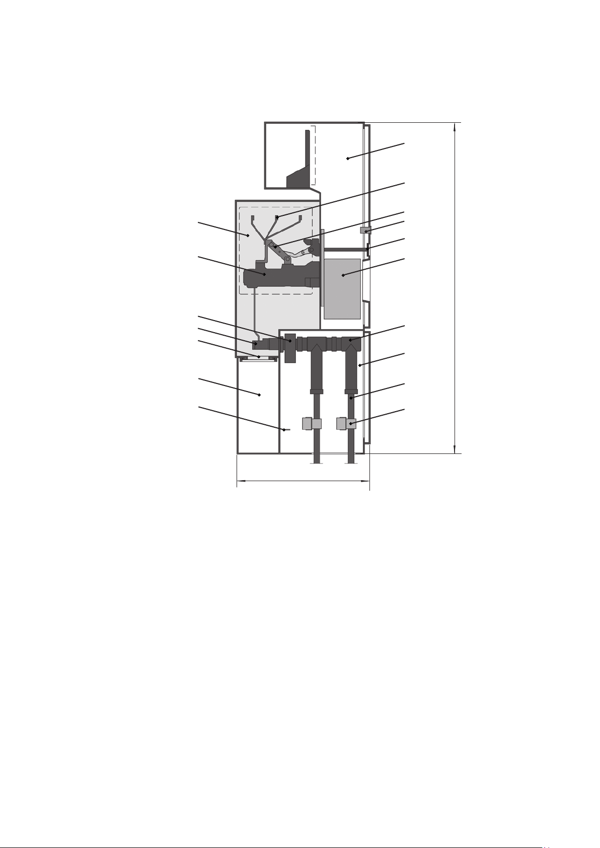
Fig. 1: Circuit-breaker panel, 800 A, panel width 400 mm, example configuration
1.0
6.0
2.1
2.3
1.5
2.4
1.1
1.9
1.3
1.13
4.0
3.5
1.2
2100 mm (2250 mm)
3.1
3.0
3.2
3.3
850 mm
1.0 Panel module
1.1 Circuit-breaker pole
1.2 Circuit-breaker operating
mechanism
1.3 Outer cone
1.5 Sockets for capacitive voltage
indicator system
1.9 Current transformer
1.13 Pressure relief disk
2.1 Busbar
2.3 Three position disconnector
2.4 Operating mechanism for three
position disconnector
3.0 Cable termination compartment
3.1 Cable connector
3.2 High voltage cable
3.3 Cable clamp
3.5 Main earthing bar
4.0 Pressure relief compartment
6.0 Low voltage compartment
Manual ZX0 HB 600 en - Revision 05 | 9

1. Despatch and storage
The possible packaging methods are as follows:
− No packaging
1.1 Condition on delivery
− The panels have been assembled into system blocks ready
for operation.
− The panel blocks have been routine tested to IEC 62271-
200.
− The busbar sockets are sealed with plastic film to protect
them during transport.
The busbar sockets are not shockproof in this
transport condition. Do not operate the switchgear
with sealed busbar sockets (e.g. on extendable end
panels). Close off unused busbar sockets with shockproof
blanking plugs (see section 2.3.3).
− In normal cases, the gas compartments have been filled
with sulphur hexafluoride (SF6) insulating gas to the rated
filling pressure. When airfreighted, however, the panel
blocks are delivered with reduced pressure.
− If delivered by airfreight, increase the pressure to the
rated filling pressure before installing the panels (see
instruction manual HB 605 E for the procedure to be
adopted).
− Packaged in plastic sheeting
− Packaged in plastic sheeting and surrounded by protective
cardboard
− Heat sealed in plastic sheeting with drying agent enclosed
− Packaged in aluminium foil in transport crate with drying
agent enclosed
1.4 Handling
− The transport units are the panel blocks.
− Always handle the panel blocks in the upright position.
− Take account of the weight of the transport units when
selecting the handling equipment.
Due to the high centre of gravity of the panel blocks,
there is a risk that the transport units may tip over! Take
all precautions to protect personnel and the materials
transported.
Only ever handle the panel blocks by
− The installation material and accessories and the documentation are packaged separately from the panel blocks.
1.2 Delivery
Check the consignment for completeness and freedom from damage. Document any transport damage found on the waybill and
inform us of it immediately. Take photographs of the damage.
1.3 Packaging
The panel blocks have been prepared for transport by the agreed
method and for the desired duration of any interim storage required. Details of the length of preservation and the storage location (indoors or outdoors) can be found in the order documents. If
the panel blocks are packaged, they are mounted on a pallet and
secured to prevent them from slipping.
− fork lift truck,
− trolley jack,
− crane, or
− hydraulic lift trolley.
1.4.1 Handling by fork lift truck
or trolley jack
The panel block must be standing on a pallet. The pallet
must rest fully on the forks of the truck or jack. The high
centre of gravity means there is a high risk of tipping.
Avoid jerky motions.
10 | Manual ZX0 HB 600 en - Revision 05

1.4.2 Handling by crane
− The methods of handling by crane differ, depending on
the width of the panel blocks. Up to a block width of 1 m,
there are lugs on the top of the panel modules for fastening
of the suspension ropes (figure 1.4.2.1), and from a width
of 1.2 m upwards there are transport crossbeams with lugs
for fastening of the suspension ropes located at the bottom
(figure 1.4.2.2).
− Attach suspension ropes of a sufficient load bearing capacity (see section 10, Technical data, for the panel weights) to
the lugs with shackles (figure 1.4.2.1). The ABB scope of
supply does not include suspension ropes and shackles.
Fig. 1.4.2.1: Crane handling of a block with width up to 1 m Fig. 1.4.2.2: Crane handling of a block with width of 1.2 m and more
Manual ZX0 HB 600 en - Revision 05 | 11

1.4.3 Handling by hydraulic lift trolley
− Attach one hydraulic lift trolley (figure 1.4.3.1) of suitable
load bearing capacity to each of the left and right sides
of the panel block in accordance with the manufacturer’s
instructions.
The high centre of gravity means there is a high risk
of tipping. Avoid jerky motions!
Fig. 1.4.3.1: Handling by hydraulic lift trolley
12 | Manual ZX0 HB 600 en - Revision 05

1.5 Intermediate storage
− Store the panel blocks in the upright position.
2. Installation of the
switchgear at site
− Do not stack the panel blocks.
− Protect the transport units from damage.
The conditions for optimum intermediate storage without
packaging or with basic packaging are as follows:
− The storeroom must comply with the normal operating
conditions for a switchgear installation (see IEC 62271-1).
− Cover the unpackaged panel blocks with protective sheeting, remembering to preserve sufficient air circulation.
− cccc
The conditions for optimum intermediate storage with
packaging and preservation are as follows:
− Check the packaging for damage.
− Store the transport units in a dry place protected from the
weather.
− Contact us if
2.1 Fundamental notes on
installation work
2.1.1 General site requirements
At the start of installation, the switchgear room at site must be
complete and fitted with lighting and power for the installation
work. It must also be lockable, dry, and with good ventilation facilities. All necessary provisions such as openings, ducts, etc. for
laying of the power cables must already be in place. Compliance
with the conditions for indoor switchgear to IEC 62271-1 must be
ensured.
2.1.2 Tightening torques
Use DIN screws of tensile class 8.8. Use the tightening torques
stated in table 2.1.2.1. The tightening torques apply to unlubricated screw connections.
− the storage life of the preservation is exceeded,
− the packaging with preservation is damaged.
Please consult the manufacturer’s installation instruc-
&
and surge arresters.
Table 2.1.2.1: Tightening torques
Nut on studbolt 12,5
Steel screw in pulling nut 18 - 24
Screw in inner cone socket 20
Other screws of tensile class 8.8 26 50
tions for the tightening torques of cable connectors
M 8 M 10
Manual ZX0 HB 600 en - Revision 05 | 13

2.1.3 General information
on treatment of plug in connectors with
silicone insulating parts
This section generally explains the procedure for treatment of sili-
cone insulating parts in the busbar sockets, blanking plugs for the
busbars, the silicone insulating parts on plug-in voltage transformers and blanking plugs for voltage transformer sockets. Only treat
the silicone parts immediately before use. Section 2.3 indicates
when the treated silicone parts are needed.
Please consult the documents from the cable connector manufacturer for details of the treatment procedure for silicone insulating
parts on the cable connectors.
− Remove surplus or dirty grease from the silicone part with
a soft, clean, non-fraying cloth.
− Clean the silicone insulating part when required with intensive cleaner M.X.T. 60 forte and a soft, non-fraying cloth.
Only use intensive cleaner M.X.T. 60 forte as the
?
− Only moisten the cloth slightly with intensive cleaner. Apply
only moderate pressure when cleaning the insulating parts
of busbar connections. Do not wipe from the black areas
towards the light insulating surfaces. By adopting this procedure you avoid transferring black, conductive material
onto the light, insulating area.
− After cleaning with intensive cleaner M.X.T. 60 forte, wipe
the silicone insulating part with a dry cloth.
cleaning agent.
− Perform the following work to prepare silicone insulating
parts for assembly:
− Inspect the silicone insulating parts
− Clean soiled silicone insulating parts
− Grease the insulating parts
− Clean the sockets, the contact tubes and the outer cone
Inspecting the silicone insulating parts
Only remove the relevant component from its protec-
?
?
?
with our service department.
tive packaging immediately before assembly.
Check the silicone insulating part for damage prior to
installation.
If you note any damage on the silicone insulating part,
only use the component after this has been agreed
As the cleaner causes the silicone to swell slightly, it
?
Greasing the insulating parts
Grease the components immediately before use as follows:
Use the quantities of assembly paste listed in table 2.1.3.1.
− Silicone insulating parts on the busbar connection:
Evenly grease the light, outer areas of the silicone part as
shown in figure 2.1.3.1.
− Blanking plugs for the busbar connection:
Evenly grease the light, outer areas of the silicone part as
shown in figure 2.1.3.2.
− Silicone insulating parts of plug-in voltage transformers or
test plugs:
Evenly grease the silicone part as shown in figure 2.1.3.3.
− Silicone insulating parts of the blanking plugs for voltage
transformers sockets:
Evenly grease the silicone part as shown in figure 2.1.3.4.
then has to dry for approx. 15 minutes in the air.
The silicone surface must be free of
− gas bubbles,
− scoring,
− damage,
− abrasions,
− foreign bodies.
Cleaning of soiled silicone insulating parts
− Perform cleaning work immediately before assembly of the
relevant component as follows:
14 | Manual ZX0 HB 600 en - Revision 05
Table 2.1.3.1: Quantities of assembly paste for silicone insulating parts
Component
Silicone insulating part on the
busbar connection, both
Blanking plugs for the busbar
bushing, silicone insulating parts
of voltage transformers or blanking
plugs for voltage transformer
sockets
Quantity of assembly paste to be
used
Approx. 20 g each
insulating part
Approx. 10 g
each part

Cleaning the sockets, the contact tubes and the outer
cone
− Degrease and clean the mating piece for the silicone
insulating part (the busbar socket or socket for the voltage
transformer) with intensive cleaner M.X.T. 60 forte.
− Clean the outer cone on the cable connector with intensive
cleaner M.X.T. 60 forte.
Assemble the components immediately to avoid
?
soiling.
Fig. 2.1.3.1: Greasing the light, outer areas of the silicone insulating part on
the busbar connection
Fig. 2.1.3.2: Greasing the light, outer area of the blanking plug for the busbar bushing in the area between the arrows
Fig. 2.1.3.3: Greasing the silicone insulating part of the voltage transformer
in the area between the arrows
Fig. 2.1.3.4: Greasing the silicone insulating part of the blanking plug for
voltage transformer sockets in the area between the arrows
Manual ZX0 HB 600 en - Revision 05 | 15

2.1.4 Handling sulphur hexafluoride
(SF6)
As a rule, no gas work is required during installation.
We recommend that gas work should only be performed by personnel trained in the handling of SF6.
Gas may only be extracted by certified personnel.
See manual HB 605 “Use of SF6 insulating gas” for details on
handling SF6.
2.2 Foundation bars
− When a raised false floor is used, load-bearing sections of
the floor frame serve as supports for the panel blocks. No
additional foundation frame is necessary.
The slabs of the raised false floor must be fas-
?
− If there is a concrete floor and the switchgear consists of
several panel blocks (with busbar connections), a foundation frame is required. Standard foundation frames supplied by ABB must be embedded in the floor topping.
?
raised false floor:
− Evenness tolerance: ± 1 mm / m
− Straightness tolerance: Max. 1 mm / m, but max. 2 mm for
the entire length
&
If no standard ABB foundation frames are used, observe the relevant construction and laying drawings for the special frames.
The standard foundation frames are shown in figure 2.2.1.
tened to the supporting frame.
Maintain the following evenness and straightness tolerances when installing the foundation frame or a
Consult the order documents for the position of the
foundation bars in the switchgear room.
Fig. 2.2.1: Foundation frames, top view
a)
(400 mm)
rear side
b)
(814 mm)
(814 mm)
(400 mm)
front side
a) For feeder panels, width 400 mm
b) For metering, sectionalizer and riser panels, width 400 mm
16 | Manual ZX0 HB 600 en - Revision 05

c)
rear side
d)
rear side
(965 mm)
(600 mm)
front side
c) For panels of 600 mm width
d) For air-insulated metering panels, width 1000 mm
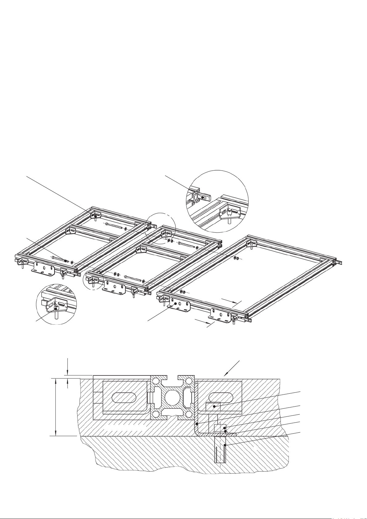
2.2.1 Installation of the standard
foundation frame
(890 mm)
(1000 mm)
front side
Standard foundation frames are delivered to site completely preassembled.
Installation principle:
The foundation frames are bolted together at the front and rear.
Vertical alignment is effected by jacking screws. Brackets are
used to fasten the frames to the floor. The foundation frames are
finally embedded in the floor topping to provide their load bearing
capacity.
Detailed description of installation
(Fig. 2.2.2.1)
- Position the foundation frame sections in the correct loca-
tions on the concrete floor.
- Align the foundation frame vertically with the four screws
(1), taking account of any deviation in floor level in the
direction of the foundation frames which are still to be laid.
- Fasten the brackets (2) of the foundation frame to the
floor, using one knock-in anchor (5) and one screw (3) with
dished washer (4) for each bracket.
- Slide a slot rod (6) into the front slot of the front section
and, if the rear sections of the two frames to be connected
are aligned (i.e. have the same depth) a slot rod into the
rear slot of the rear section. Tighten the grub screws in the
slot rods.
- Place the following foundation frame in the correct position
on the floor, allowing the inserted slot rods to slide into the
sections of the frame to be installed. Bolt the foundation
frames together with two M 8 x 100 cheese head screws
(7) and nuts and washers. Tighten the grub screws in the
slot rods.
- Align the foundation frame vertically as described above
and fasten it to the floor.
- Install the following foundation frames in the same way.
Manual ZX0 HB 600 en - Revision 05 | 17
- Earth the completely assembled frame. Further details on
this can be found in the order documents.
When applying the floor topping, carefully fill under
?
Fig. 2.2.1.1: Installation of the floor frame
the foundation frame with topping material.
1
7
1
1
A
A
2
Section A-A
Top of finished floor
< 3
55 ± 5
18 | Manual ZX0 HB 600 en - Revision 05
Floor topping
1
2
3
4
5

2.3 Assembly of the
switchgear
2.3.1 Preparatory work
− Remove the protective cap (2) from the filling connector (1)
by turning it counter-clockwise.
Do not press the valve pin (3) in, as otherwise gas will
?
− While pulling the locking ring (4) outwards, press the coupling of the pressure gauge (5) into the filling connector.
flow out of the valve.
2.3.1.1 Checking the SF6
pressure in the gas
compartments
Each panel block (= delivery unit) forms a gas compartment and is
fitted with one filling connector. The filling connectors are located
in the low voltage compartments and are accessible from the front
when the low voltage compartment door is open.
− Check the gas pressure in each gas compartment with
a temperature-compensated pressure gauge (see list of
tools) before aligning and connecting the panel blocks, as
follows:
Fig. 2.3.1.1.1: Filling connector (1) with protective cap (2) in the low voltage
compartment
1
− Check the reading on the scale of the pressure gauge.
The reading must be in the green area of the instru-
?
than 1000 m, please contact us.
− Remove the pressure gauge by pulling out the locking
ring on the filling connector.
− Screw the protective cap onto the filling connector.
Fig. 2.3.1.1.2: Filling connector (1) with valve pin (3)
ment’s scale. If it is not, or if the site altitude is greater
1
2
Fig. 2.3.1.1.3: Filling connector with pressure gauge (5) and locking ring (4)
4
5
3
Manual ZX0 HB 600 en - Revision 05 | 19

2.3.1.2 Greasing the foundation bars
For standard foundation frames supplied by ABB, remove the
protective film. Grease the top surfaces of the foundation frame or
raised false floor beams. This facilitates erection and alignment of
the panel blocks.
2.3.1.3 Preparing the panel blocks
− Remove the covers from the cable termination compartments on all panel blocks.
− Screw guide pins to the side of the panel block to be extended, using a threaded plate (see figure 2.3.1.3.1).
In the cases of sectionalizer, riser or metering panels, there is
a second fastening bracket below the busbar bushings. Fit the
guide pins to this fastening bracket using a threaded plate (figure
2.3.1.3.3).
Guide pins are only to be fitted to one of the panel
?
guide pins remain in the relevant position after erection of the
panel blocks and must not be removed.
− Lightly grease the guide pins for better sliding.
block at the joint between two panel blocks. The
Fig. 2.3.1.3.1: Fitting the guide pins using a threaded plate
Fig. 2.3.1.3.2: Fitted guide pins
Fig. 2.3.1.3.3: Position of the guide pins in sectionalizer, riser and metering
panels
20 | Manual ZX0 HB 600 en - Revision 05

2.3.2 Erection of the panel blocks
- Set up the furthest panel block precisely at the specified
position.
When the standard foundation frame is used:
- Insert M 8 T-nuts through the holes in the floor plates into
the slots in the foundation frame sections. Join the floor
plates using washers (1 x washer 8.5 x 30 x 3 and 1 x
dished washer 8) and M 8 x 16 cheese head screws to the
previously positioned T-nuts (Fig. 2.3.2.1and Fig. 2.3.2.2).
Fig. 2.3.2.1: View of the fastening points for the panels
400 mm
- Each panel is fastened to the foundation frame with four
screws (Fig. 2.3.2.1).
When a special foundation frame or raised false floor is used:
Fasten the panels in accordance with the instruction
&
documents supplied.
Section A-A
Panel floor
(simplified)
Coupler panel
Riser panel
Metering panel
T-nut M8
Feeder panel
400 mm
600 mm
Washer 8,5 x 30 x 3
Dished washer
Cheese head screw
M8 x 16
Floor frame
A
A
Manual ZX0 HB 600 en - Revision 05 | 21

Fig.. 2.3.2.1: Fastening the panel to the foundation frame
Slot in the foundation frame section
T-nut, M8
Fastening of the panel to the foundation frame
22 | Manual ZX0 HB 600 en - Revision 05

− Check the position of the panel block and align the panel
block to the precise dimensions if necessary.
− Tighten the fastening screws in the panel block.
Increased force is required to overcome the spring
?
before the contact tube can be pressed into the socket up to
the stop.
force of the spiral contact inside the busbar socket
− Remove the protective film from the busbar sockets on the
panel block which has been erected and the next panel
block to be erected (figure 2.3.2.2).
− Prepare the silicone insulating parts, contact tubes and
busbar sockets for the busbar connection between the two
panel blocks as described in section 2.1.3.
− Insert the contact tubes into the busbar sockets of the
panel which has been erected until they reach a tangible
stop (figure 2.3.2.3).
Fig. 2.3.2.2: Protective film for busbar sockets
− Carefully insert the silicone insulating parts into the busbar
sockets of the panel block which has already been erected.
(figure 2.3.2.4).
Align the contact tubes horizontally.
?
Fig. 2.3.2.4: Fitted contact tubes and silicone insulating parts
Fig. 2.3.2.3: Inserting a contact tube
Fig. 2.3.2.5: Positioning of the panel block to be erected
Manual ZX0 HB 600 en - Revision 05 | 23

− Slide the extension panel carefully against the existing system without tipping it, in such a way that the contact tubes
slide into the busbar sockets and the guide pins into the
corresponding bores in the fastening bracket.
Apply drawing or pressing tools to a large area on
?
instance by using a wooden beam between the tool and the
panel block) so as to avoid damage to the panel block.
− As soon as the distance between the two panel blocks is
small enough, insert two M10 x 40 cheese head screws
into the bores provided in the fastening bracket. Dismantling the lid in the rear wall of the low voltage compartment
the panel blocks directly above the floor (for
facilitates access to the front screw connection from inside
the low voltage compartment (figure 2.3.2.6).
− The rear screw connection is located behind the low voltage compartment. Turn both the screws into the pulling
nuts on the previously assembled threaded plate and
tighten the screws alternately (figure 2.3.2.7 ).
− Connect the low voltage compartments and cable termination compartments of the two panel blocks at the specified
locations (figure 2.3.2.8) with the aid of screws.
Fig. 2.3.2.6: Screw connections between the panel blocks: Accessibility of
the front screw connection from the inside of the low voltage compartment
Tool inside
the low voltage compartment
Fig. 2.3.2.7: Complete screw connections on the fastening brackets
Fig. 2.3.2.8: Further fastening points on the panel blocks
24 | Manual ZX0 HB 600 en - Revision 05
Fig. 2.3.2.9: Screwing the low voltage compartments together
 Loading...