

ABB ZS4-S-R1 Catalog Page
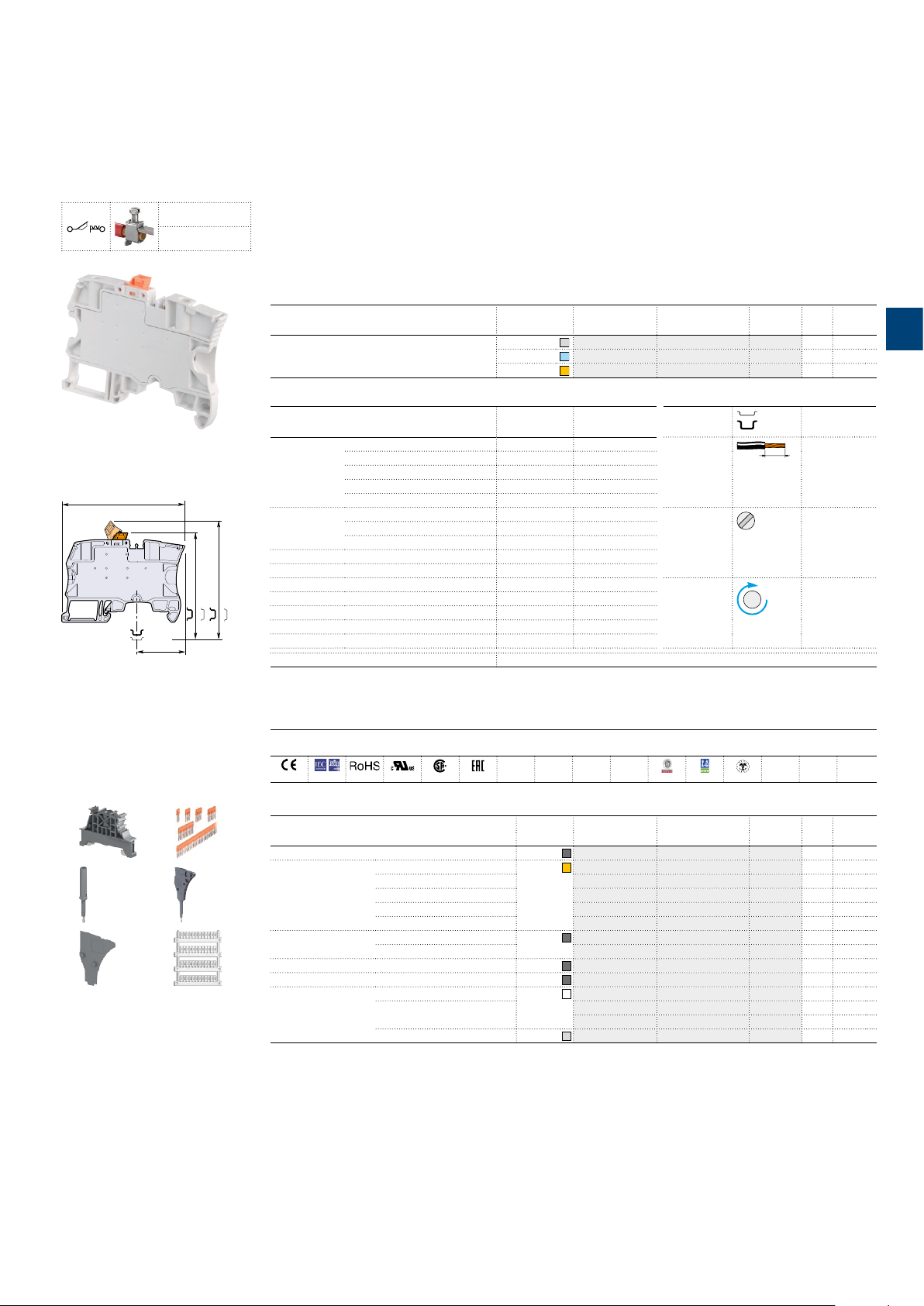
ZS4-S-R1 screw clamp terminal blocks
70.5 2.78"
CE
CB
RoHS
USR CNR
CSA
EAC
BV
DNV
Rina
Disconnect with blade -
4 mm²
10 AWG
ZS4-S-R1
Description
– Simplify the alternated distribution thanks to the two jumper channels aligned with ZS4 feed-through termi-
nal blocks,
– Ease your disconnect operations with the disconnect blade operated by hand or with a screwdriver.
Ordering details
Description Color Type Order code
Disconnect Profile aligned with ZS4-SF
1SNK161003F0014
Main technical data Mounting instructions
Connecting capacity IEC
1 conductor
per clamp
2 conductors
per clamp
Rated current / Rated cross section 26 A
Rigid - Solid / Stranded 0.2 ... 4 mm² 24 ... 10 AWG
Flexible 0.22 ... 4 mm² 0.412 in
with non insulated ferrule 0.22 ... 4 mm² 24 ... 12 AWG
with insulated ferrule 0.22 ... 4 mm² 24 ... 12 AWG
Gauge A3-B3
Rigid - Solid / Stranded 0.2 ... 1.5 mm² 24 ... 16 AWG
Flexible 0.2 ... 1.5 mm²
with twin ferrule 0.22 ... 1.5 mm² 24 ... 16 AWG
6 mm 0.236 in spacing
Grey
ZS4-S-R1 1SNK506310R0000 50 13.20
Blue
Orange
/ 4 mm² 26 A / 10 AWG
ZS4-S-R1-BL 1SNK506320R0000 50 13.20
ZS4-S-R1-OR 1SNK506330R0000 50 13.20
UL - CSA
Pkg
Weight
qty (1 pce)
Rail TH 35-7.5,
TH 35-15
Wire stripping
10.5 mm
length
Tool
Flat screwdriver
Ø
3.5 mm
Ø
0.138 in
g
3
26.7 1.05"
6 mm 0.236 in spacing
1 2
3
5
4
6
60.4 2.37"
52.9 2.08"
67.2 2.64"
Rated short-time withstand current
59.7 2.35"
(1s) 480 A
Torque
Rated voltage 400 V 150 V
Impulse withstand voltage 6000 V
Protection IP20 NEMA 1
Recommendation for best usage: in horizontal assemblies, disconnect terminal blocks should be mounted
with fixed foot on top (power side) so that the disconnect knife does not partially close through gravity.
Furthermore, as specified per IEC 60947-7-1, disconnect terminal blocks are intended to be used for temporary
disconnection at zero potential and at no load.
The connecting capacity data for one Rigid - Solid / Stranded - Flexible conductor (when applicable) is a mandatory information required by IEC, UL and CSA standards (Copper conductors).
All other data are provided as supplementary information only. For more details, please consult our CB, UL or CSA certificates and technical datasheet available on http://www.ABB.com
Accessories
Description Color Type Order code Pkg Weight
1 End stops 10 mm 0.394 in
2 Jumper bars 2 poles 41 A (IEC)
3 poles 41 A (IEC) JB6-3 1SNK906303R0000 50 2.10
4 poles 41 A (IEC) JB6-4 1SNK906304R0000 50 2.90
5 poles 41 A (IEC) JB6-5 1SNK906305R0000 50 3.60
10 poles 41 A (IEC) JB6-10 1SNK906310R0000 20 7.40
3 Test adapters For test plugs DIA 2 mm 0.079 in
For test plugs DIA 4 mm 0.157 in TP4 1SNK900205R0000 20 2.40
4 Test connectors End module, 5.2 mm 0.205 in
5 Spacers 0.8 mm 0.031 in
6 Terminal block
markers
Blank marker
Blank card MC612 1SNK150000R0000 22 10.00
Universal wire markers holder
Complete list of accessories is indicated in the terminal block datasheet including end stops.
Some accessories such as jumper bars may modify the terminal block's ratings: Complete information available in the accessories section of the catalog.
Dark grey
Orange
Dark grey
Dark grey
Dark grey
White
Grey
BAM4 1SNK900001R0000 50 14.00
JB6-2 1SNK906302R0000 50 1.30
TP2 1SNK900203R0000 20 1.70
TC5-R1 1SNK900201R0000 10 5.20
ES-TC6 1SNK900105R0000 10 0.80
MG-CPM 13 41791
1SNB041791R0612 1680 0.27
MC612PA 1SNK159999R0000 20 11.00
UMH 1SNK900611R0000 10 0.20
0.6 Nm ± 0.1
5.31 lb.in ± 0.885
qty (1 pce)
g
All the te chnic al data fo r UL/CSA st andard and dime nsion s in inch es are in i talic.
Technical data valid for copper conductors only.
1SNK161012S0201
ABB SNK series - Terminal blocks | 103
 Loading...