

Page 1
Technical Datasheet Catalogue Page
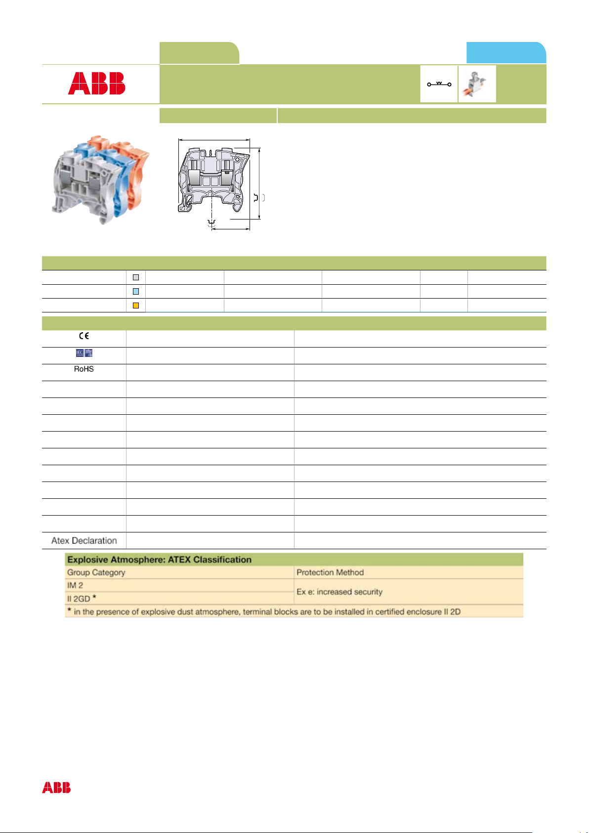
57.8 2.28"
56.1 2.21"
29.8 1.17"
50.3 1.98"
CE
CB
RoHS
1SNK 161 017 D0201 1SNK 161 017 S0201
ZS16 Screw Clamp Terminal Block
Feed-through
10 mm 0.394 in Spacing
3D CAD outline drawings available on "Control Product 3D" portal
Ordering Details Type Order Code EAN Code
Grey
Blue
Orange
ZS16 1SNK 510 010 R0000 3472595100101 25 20.20
ZS16-BL 1SNK 510 020 R0000 3472595100200 25 20.20
ZS16-OR 1SNK 510 030 R0000 3472595100309 25 20.20
Declarations and Certificates Document Part Number
UE Directive 1SND 225 081 C1006
Third Party Certificate 1SND 161 021 A0200
Features and Benefits
Save space by connecting conductors up to 16 mm² (CB certied) 4 AWG
in just 10 mm 0.394 in spacing.
Pack
(ing)
Weight g (1 pce)
16 mm²
4 AWG
RoHS 1SND 230 491 F0203
Atex Declaration 1SND 225 085 C1003
1
Page 2
General Information
2
The following information must be strictly adhered to in order to guarantee the terminal block electrical, mechanical and environmental performance.
Protection IP 20 NEMA 1
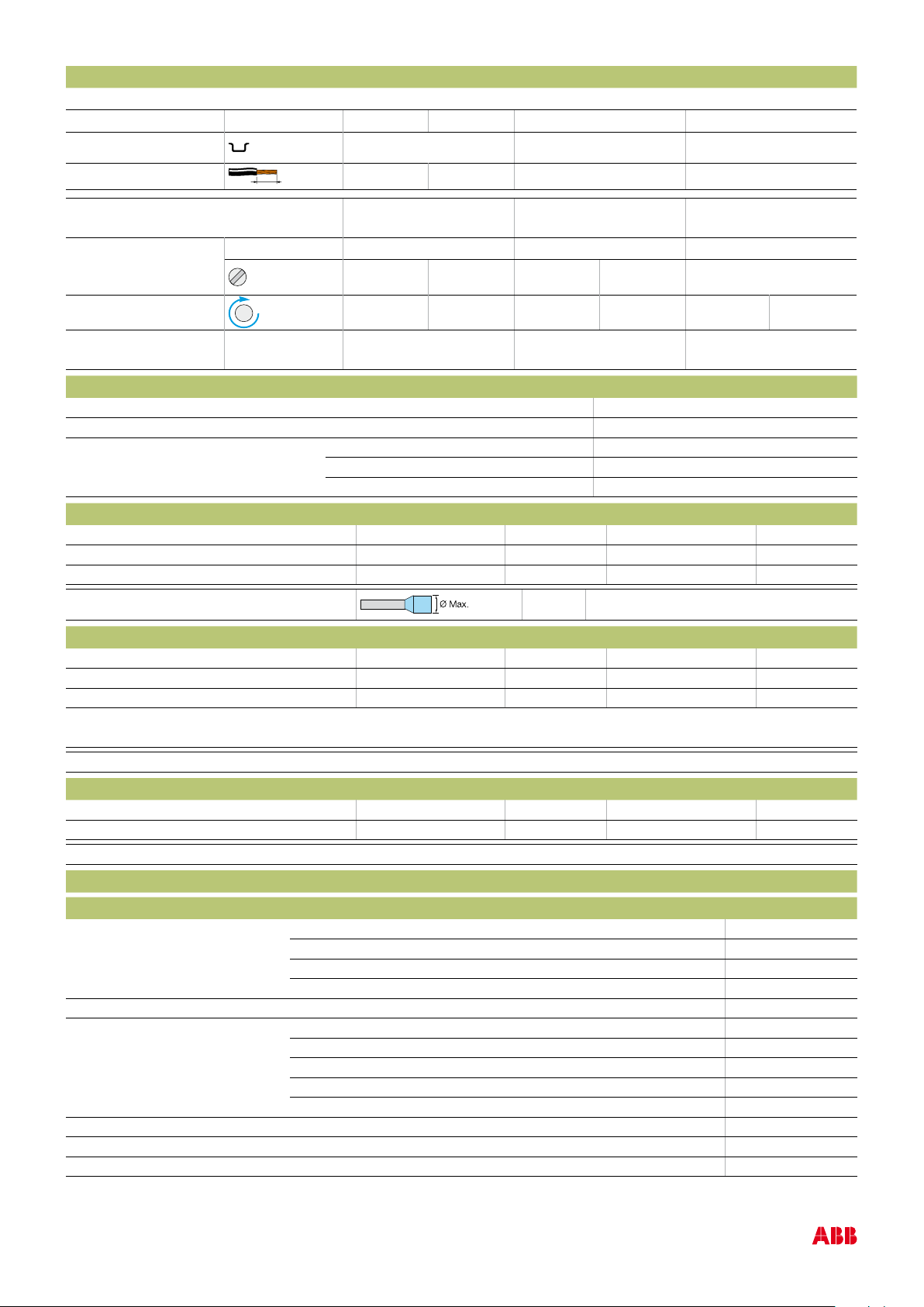
Rail
Wire stripping length
Operating tool
Torque
Mechanical endurance
of disconnect system
DIN3-TH35
13.5 mm 0.531 in
Screw clamp Screw rail contact
(Maximum value)
Flat screwdriver
5.5 mm 0.217 in
1.8 Nm 15.93 lb.in
± 0.2 Nm ± 1.77 lb.in ± 0.2 Nm ± 1.77 lb.in
Material Specifications
Insulating material Polyamide
IRC 600 V
Flammability UL94 V0
NF F 16 101 I2F2
Needle ame test IEC 60695-11-5 Compliant
Connecting capacity per clamp
1 Rigid conductor 0.5-16 mm² 20-4 AWG
1 Flexible conductor without ferrule 0.5-16 mm² 20-4 AWG
1 Flexible conductor with ferrule 0.5-10 mm² 20-8 AWG
Ferrule maximum outer diameter
8.2 mm 0.323 in
Multi Connecting capacity per clamp
2 Rigid conductors 0.5-4 mm² 20-12 AWG
2 Flexible conductors without ferrule 0.5-4 mm² 20-12 AWG
2 Flexible conductors with twin ferrule 0.5-4 mm² 20-12 AWG
Don't mix solid and flexible conductors in the same clamp
Don't mix solid or flexible conductors of different sizes in the same clamp
The "Connecting capacity with ferrule " data is guaranteed with ABB crimping tool PS-3
Cross section
Rated cross section 16 mm² 4 AWG
Maximum Cross section Manufacturer data 16 mm² Manufacturer data 4 AWG
Gauge A6-B6 / 6.4 mm / 0.252 in / IEC 60947-7-1
Electrical characteristics
Current
Rated current IEC 60947-7-1 76 A
Field and factory wiring Cat.2 UL 1059 67 A
Factory wiring Cat.1 UL 1059 67 A
CSA-C-22.2 n° 158 67 A
Rated short-time withstand current 1 s (Icw) 1920 A
Short-time withstand current 0.5 s Manufacturer data
5 s Manufacturer data
10 s Manufacturer data
30 s Manufacturer data
1 mn Manufacturer data
Rated short circuit withstand CSA-C-22.2 n° 158
Max. current (45° temperature increase) / Max. cross section (mm²) Manufacturer data 76 A 16 mm²
Maximum short circuit current (1s) Manufacturer data 1920 A
Page 3

Short Circuit Current Rating (SCCR) SA UL 1059 supplement
ZS16 Terminal block
76.0A
71.7A
67.0A
62.1A
56.6A
50.7A
43.9A
35.8A
25.3A
0.0A
0
10
20
30
40
50
60
70
80
55 65 75 85 95 105 115
AMBIANT TEMPERATURE (°C)
CURRENT (A)
3
SCCR UL 1059
With the following congurations:
Maximum voltage
Suitable conductor wire range
Fuse rating
Fuse designation
Fuse manufacturer name
Fuse type
Short circuit current
Voltage
Rated voltage IEC 60947-1 1000 V
Rated voltage UL 1059 600 V
Use Group UL 1059 C
Rated voltage CSA-C-22.2 n° 158 600 V
Rated voltage Ex e IEC/EN 60079-11 630 V
Rated impulse withstand voltage 8000 V
Dielectric test voltage 2200 V
Pollution degree IEC 60947-1 3
Overvoltage category IEC 60947-1 III
Dissipated power
Maximum dissipated power at rated current
IEC 2.4 W
Rated power dissipation at an ambient temperature of 23 °C - IEC 60947-7-3
Overload and short-circuit protection
Separate arrangement
Exclusive short-circuit protection
Separate arrangement
1 fuse and 4 feed-through blocks
Overload and short-circuit protection
Compound arrangement
Exclusive short-circuit protection
Compound arrangement
5 fuse blocks
Temperature range
Ambient temperature min/max Storage -55 +110 °C -67 +230 F
Installing -5 +40 °C -23 +104 F
Service IEC 60068-2-1 -55 +110 °C -67 +230 F
EN 60079-7 -55 +85 °C
Current Derating curve for continuous service temperature
Page 4

Environmental Characteristics
4
Additional climatic tests
Dry heat IEC 60068-2-2 Compliant
Conditions Temperature +100 °C
Duration of test 96 h
Cyclic damp heat IEC 60068-2-30 Compliant
Conditions Temperature +55 °C
Number of cycles 2
Cold IEC 60068-2-1 Compliant
Conditions Temperature -40 °C
Duration of test 96 h
Z/ABDM climatic sequence IEC 60068-2-61 Compliant
Conditions Dry heat Duration of test / Temperature 16 h +85 °C
Cyclic damp heat Number of cycles / Temperature 1 +55 °C
Cold Duration of test / Temperature 2 h -25 °C
Corrosion
Salt mist IEC 60068-2-11 Compliant
Conditions Duration of test 96 h
Concentration 5 %
SO2 ISO 6988 Compliant
Conditions Duration of test 48 h
Concentration 0.2 dm³
Sulfur dioxide IEC 60068-2-42
Conditions Duration of test
Hydrogen sulfur IEC 60068-2-43
Conditions Duration of test
Flowing mixed gas corrosion test IEC 60068-2-60
Conditions Number of the test method
Duration of test
Vibrations
Vibrations IEC 60068-2-6 Compliant
Conditions Frequency range 10-55 Hz
Number of cycles 10
Amplitude
Acceleration 10 m/s²
Ramdom vibrations and climatic sequence IEC 60068-2-64
Conditions Duration of test
Frequency range
Acceleration
Climatic cycles
Step 1 -> Temperature / Duration of test
Step 2 -> Temperature / Duration of test
Temperature variation per minute
Page 5

ZS16 Terminal Block Accessories Compatibility
5
Description Type Order Code
1
End Stops
End Sections
2
Jumper Bars
3
Circuit Separators
4
Test Adapters
5
Test Connectors
6
Protecting Covers
7
Protecting Cover Kits
8
Tools
9
Terminal Block Markers
10
BAM3 1SNK 900 001 R0000 50 13.80 1SNK 160 026 D0201
ES4 1SNK 505 910 R0000 20 2.18 1SNK 160 022 D0201
JB10-2 1SNK 910 302 R0000 50 4.60 1SNK 160 031 D0201
JB10-3 1SNK 910 303 R0000 50 7.10 1SNK 160 031 D0201
JB10-4 1SNK 910 304 R0000 40 9.40 1SNK 160 031 D0201
JB10-5 1SNK 910 305 R0000 30 12.00 1SNK 160 031 D0201
JB10-10 1SNK 910 310 R0000 20 24.00 1SNK 160 031 D0201
CS 1SNK 900 101 R0000 20 0.20 1SNK 160 018 D0201
CS-R1 1SNK 900 103 R0000 20 5.20 1SNK 160 018 D0201
TP2 1SNK 900 203 R0000 20 1.73 1SNK 160 036 D0201
TP4 1SNK 900 205 R0000 20 2.42 1SNK 160 036 D0201
TC5-R1 1SNK 900 201 R0000 10 5.23 1SNK 160 042 D0201
CO 1SNK 900 604 R0000 1 300.00 1SNK 160 020 D0201
PL10 1SNK 900 621 R0000 10 3.13 1SNK 160 021 D0201
KCO 1SNK 900 624 R0000 1 47,8 1SNK 160 028 D0201
PS-3 1SNK 900 650 R0000 1 380.00 1SNK 160 024 D0201
MC812 1SNK 160 000 R0000 22 0.09 1SNK 160 009 D0201
UMH 1SNK 900 611 R0000 10 0.20 1SNK 160 001 D0201
PROCAP8 1SNK 900 613 R0000 20 1.00 1SNK 160 013 D0201
SAT8 1SNK 900 616 R0000 5 6.00 1SNK 160 013 D0201
(ing)
Pack
Weight Technical Datasheet
pieces g (1 pce) PDF
 Loading...