

Page 1

Instructions Manual PQFA
Power Quality Filter
ABB Jumet
Page 2

PQFA Instructions Manual
__________________________________________________________________________
Asea Brown Boveri Jumet S.A.
2
Table of contents
1. SAFETY INSTRUCTIONS ...................................................................................................................5
2. UPON RECEPTION ............................................................................................................................ 6
2.1. DELIVERY INSPECTION........................................................................................................................ 6
2.2. IDENTIFICATION TAG...........................................................................................................................6
2.3. STORAGE.......................................................................................................................................... 6
2.4. LONG STORAGE PERIOD AND REFORMING .............................................................................................6
3. PQFA PRINCIPLE AND CHARACTERISTICS....................................................................................7
3.1. REASONS FOR LIMITING HARMONICS .................................................................................................... 7
3.2. GENERAL PRINCIPLE OF ACTIVE FILTERING............................................................................................ 8
3.3. THE ABB ACTIVE FILTER: THE PQFA. .................................................................................................9
3.4. THE PQFA: PERFORMANCES ............................................................................................................ 11
3.4.1. Filtering................................................................................................................................. 11
3.4.2. Reactive power...................................................................................................................... 12
3.4.3. EMC......................................................................................................................................12
4. COMPONENTS DESCRIPTION AND IDENTIFICATION...................................................................13
4.1. COMPONENTS DESCRIPTION .............................................................................................................13
4.1.1. PQF current generator...........................................................................................................13
4.1.2. The control............................................................................................................................ 14
4.2. COMPONENTS IDENTIFICATION .......................................................................................................... 15
5. MECHANICAL INSTALLATION........................................................................................................26
6. ELECTRICAL INSTALLATION .........................................................................................................29
6.1. OVERVOLTAGE ................................................................................................................................ 29
6.2. POWER CABLES AND EXTERNAL PROTECTION......................................................................................29
6.3. CURRENT TRANSFORMERS/CONTROL CABLES SELECTION.....................................................................32
6.4. CURRENT TRANSFORMERS INSTALLATION...........................................................................................34
6.4.1. CT’s connection to the PQFA.................................................................................................34
6.4.2. CT’s connection topology: cases............................................................................................36
6.4.2.1. Case 1: Global compensation – one feeding transformer........................................................................36
6.4.2.2. Case 2: Individual compensation – one feeding transformer...................................................................37
6.4.2.3. Case 3: global compensation – transformer busbar not accessible........................................................38
6.4.2.4. Case 4: two independent feeding transformers........................................................................................40
6.4.2.5. Case 5: back up generator.........................................................................................................................42
6.5. PRECAUTIONS WITH CAPACITORS ...................................................................................................... 43
7. CUBICLES INTERCONNECTIONS................................................................................................... 44
7.1. INTRODUCTION ................................................................................................................................ 44
7.2. MECHANICAL INSTALLATION .............................................................................................................. 44
7.3. ELECTRICAL CONNECTIONS...............................................................................................................45
7.3.1. Connections between cubicles...............................................................................................45
7.3.1.1. Power connection........................................................................................................................................45
7.3.1.2. Control connection......................................................................................................................................46
7.3.1.3. Domino boards connection.........................................................................................................................47
7.3.1.4. Earth connection.........................................................................................................................................48
7.3.2. Connections to the supply......................................................................................................48
7.3.2.1. Power connection........................................................................................................................................48
7.3.2.2. Protective earth...........................................................................................................................................48
8. PQF-PROG INSTALLATION AND PC CONNECTION ......................................................................50
8.1. SYSTEM REQUIREMENTS................................................................................................................... 50
8.2. INSTALLING PQF-PROG ON YOUR PC ................................................................................................50
Page 3

PQFA Instructions Manual
__________________________________________________________________________
Asea Brown Boveri Jumet S.A.
3
HARDWARE CONNECTION..............................................................................................................................50
9. COMMISSIONING.............................................................................................................................51
9.1. STEP 1........................................................................................................................................... 51
9.2. STEP 2........................................................................................................................................... 51
9.3. STEP 3........................................................................................................................................... 52
9.3.1. PQF connection diagram....................................................................................................... 52
9.3.2. Material needed & hypotheses for correct measurements......................................................53
9.3.3. Checking the correct connection of the CTs with a two channel scopemeter...........................53
9.3.3.1. Measurement of CT in phase L1................................................................................................................53
9.3.3.2. Measurement of CT in phase L2 and L3...................................................................................................55
9.3.4. Checking the correct connection of the CTs with two current probes......................................56
9.3.5. Checking the correct connection of the CTs with a Fluke 41B.................................................56
9.4. STEP 4........................................................................................................................................... 57
9.4.1. With PQF-Prog......................................................................................................................57
9.4.2. With the PQF-Manager..........................................................................................................58
9.5. STEP 5........................................................................................................................................... 59
9.6. STEP 6........................................................................................................................................... 59
9.7. STEP 7........................................................................................................................................... 59
9.8. STEP 8........................................................................................................................................... 59
10. OPERATION..................................................................................................................................... 61
10.1. NORMAL WORKING SEQUENCE ..........................................................................................................61
10.2. OPERATION WITH CAPACITORS .......................................................................................................... 66
10.3. BEHAVIOR IN CASE OF POWER OUTAGE ..............................................................................................66
10.4. BUTTONS, LIGHTS AND LED’S SIGNIFICATION......................................................................................67
10.4.1. Master cubicle....................................................................................................................... 67
10.4.2. Slave cubicle.........................................................................................................................67
10.4.3. PQF-Manager........................................................................................................................68
10.4.4. Control rack...........................................................................................................................69
10.5. PROGRAMMING WITH PQF-PROG......................................................................................................70
10.5.1. Filter operation principle.........................................................................................................70
10.5.2. Starting.................................................................................................................................. 71
10.5.3. Programming the filter............................................................................................................73
10.6. PROGRAMMING WITH PQF-MANAGER................................................................................................75
10.6.1. Filter operation principle.........................................................................................................75
Keys identification..............................................................................................................................76
10.6.3. Programming the filter............................................................................................................77
10.7. PQFA AND NETWORK MONITORING WITH THE PQF-MANAGER..............................................................81
10.7.1. Filter status............................................................................................................................ 81
10.7.2. Network status....................................................................................................................... 82
10.7.3. Waveform.............................................................................................................................. 83
10.7.4. Spectrum............................................................................................................................... 84
10.8. REMOTE CONTROL AND ALARM CONTACT............................................................................................85
10.8.1. Remote control......................................................................................................................85
10.8.2. Alarm contact.........................................................................................................................86
10.9. PROTECTIONS ................................................................................................................................. 86
11. FAULT HANDLING AND TROUBLESHOOTING .............................................................................. 88
11.1. FAULT HANDLING .............................................................................................................................88
11.1.1. Type of faults......................................................................................................................... 88
11.1.2. Fault handling and fault clearance procedure.........................................................................88
11.2. TROUBLESHOOTING ......................................................................................................................... 91
11.2.1. Frequent problems occurring at commissioning stage............................................................91
11.2.2. Error codes meaning..............................................................................................................91
11.2.3. Faults not related to error codes.............................................................................................95
11.2.4. Restarting the filter after fault correction................................................................................. 95
Page 4

PQFA Instructions Manual
__________________________________________________________________________
Asea Brown Boveri Jumet S.A.
4
12. MAINTENANCE................................................................................................................................ 96
12.1. MAINTENANCE FREQUENCY............................................................................................................... 96
12.2. MAINTENANCE PROCEDURE ..............................................................................................................96
12.3. FAN................................................................................................................................................ 97
12.4. CAPACITORS REFORMING .................................................................................................................97
Page 5
PQFA Instructions Manual
Asea Brown Boveri Jumet S.A.
5
1. Safety instructions
These safety instructions are intended for all work on the PQFA.
Neglecting these instructions can cause physical injury and death.
All electrical installation and maintenance work on the PQFA should be
carried out by qualified electricians.
Do not attempt to work on a powered PQFA.
After switching off the mains, always wait at least 5 minutes before
working on the unit in order to allow the discharge of DC capacitors
through the discharge resistors.
DC capacitors might be charged to more than 1000V.
Before manipulating current transformers, make sure that the secondary
is short-circuited. Never open the secondary of a loaded current
transformer.
You must always wear isolating gloves and eye-protection when
working on electrical installation. Also make sure that all local safety
regulations are fulfilled.
Page 6

PQFA Instructions Manual
Asea Brown Boveri Jumet S.A.
6
2. Upon reception
2.1. Delivery inspection
Each PQFA is delivered in a sealed package designed to protect adequately
the equipment during shipment.
Upon receipt of the equipment, make sure that the packing is in good
condition.
After removal of the packing, check visually the exterior and interior of your
filter. Any loss or damage should be notified immediately.
Care should be taken to ensure that correct handling facilities are used.
2.2. Identification tag
Each PQFA is fitted with a nameplate for identification purposes. The
nameplate includes the type of filter, nominal frequency, voltage and current
as well as a serial number and an ABB internal article code.
This information should always remain readable to ensure proper identification
during the whole life of the filter.
2.3. Storage
PQFA packing is made for a storage period of maximum six months (transport
time included from delivery date EXW ABB Jumet factory). Packing for longer
storage period can be done on request.
If your PQFA is not installed once unpacked, it should be stored in a clean
indoor, dry, dust free and non-corrosive environment. The storage
temperature must be between –15°C and 70°C with a maximum relative
humidity of 95%, non-condensing.
Before installing and operating your PQFA, you should read very carefully this
instructions manual and you should make sure that the information given on
the nameplate corresponds to your network.
2.4. Long storage period and reforming
If your PQFA is non-operational or stored for more than one year, the DC
capacitors need to be reformed (re-aged). Without reforming, capacitors may
be damaged when the filter starts to operate.
The reforming methods are described in chapter 12 (maintenance).
Page 7
PQFA Instructions Manual
Asea Brown Boveri Jumet S.A.
7
3. PQFA principle and characteristics
3.1. Reasons for limiting harmonics
Power electronics based equipment is the main source of the harmonic
pollution in electric networks. Examples of such equipment include drives (AC
or DC), UPS’s, welders, PCs, printers etc.
In general, the semiconductor switches in this equipment conduct only during
a fraction of the fundamental period. This is how such equipment can obtain
their main properties regarding energy saving, dynamic performance and
flexibility of control. However, as a result a discontinuous current containing a
considerable amount of distortion is drawn from the supply.
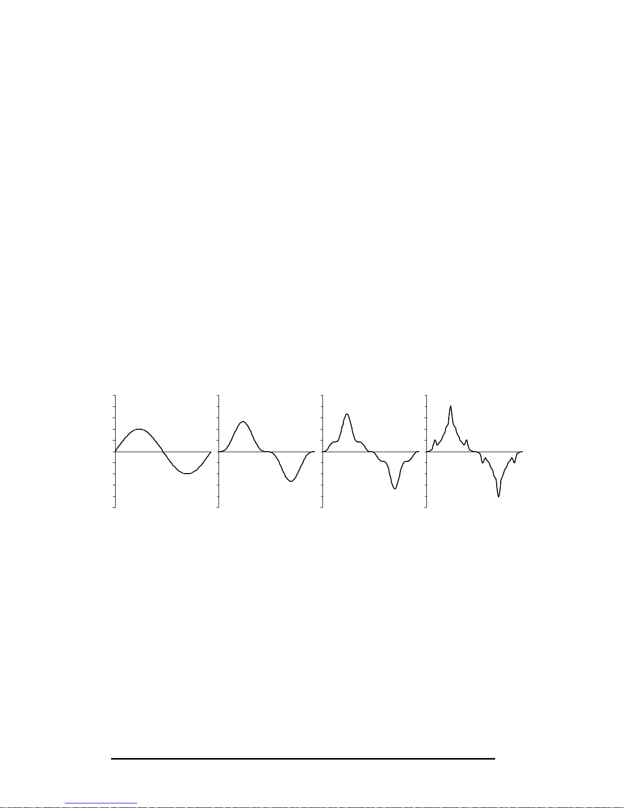
Harmonic pollution causes a number of problems. A first effect is the increase
of the RMS-value and the peak-value of the distorted waveform. This is
illustrated in figure 3.1. that shows the increase of these values as more
harmonic components are added to an initially undistorted waveform. The
RMS-value and the peak-value of the undistorted waveform are defined as
100 %. The peaks of the fundamental component and the distortion
components are assumed to be aligned. It may be seen that the distorted
waveform, which contains harmonics up to the 25th harmonic, has a peak
value that is twice the value of the undistorted waveform and a RMS-value
that is 10 % higher.
Peak: 100 % 133 % 168 % 204 %
RMS: 100 % 105 % 108 % 110 %
Figure 3.1. Evolution of the increase in peak-value and the RMS-value of
a waveform as more harmonic components are added
The increase in RMS-value leads to increased heating of the electrical
equipment. Furthermore, circuit breakers may trip due to higher thermal or
instantaneous levels. Also, fuses may blow and capacitors may be damaged.
kWh meters may give faulty readings. The winding and iron losses of motors
increase and they may experience perturbing torques on the shaft. Sensitive
electronic equipment may be damaged. Equipment, which uses the supply
voltage as a reference may not be able to synchronise properly and either
applies wrong firing, pulses to switching elements or switch off. Interference
with electronic communications equipment may occur.
100 % H1
+ 33 % H3
+ 20 % H5
… + 4 %
H25
Page 8
PQFA Instructions Manual
Asea Brown Boveri Jumet S.A.
8
Distorted networks may also cause generators malfunctions.
Overall it may be concluded that an excessive amount of harmonics leads to a
premature ageing of the electrical installation. This is an important motivation
for taking action against harmonics.
3.2. General principle of active filtering
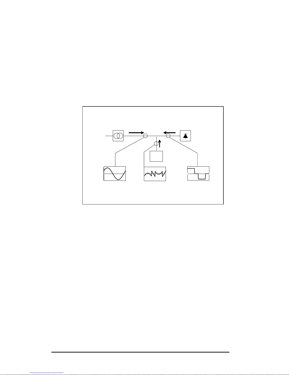
The active filter measures the harmonic currents and generates actively a
harmonic current spectrum in opposite phase to the measured distorting
harmonic current. The original harmonics are thereby cancelled. The principle
is shown in figure 3.2.
Figure 3.2. Principle of active filtering
The control of the active filter in combination with the active generation of the
compensating current allows for a concept that may not be overloaded.
Harmonic currents exceeding the capacity of the active filter will remain on the
network, but the filter will operate and eliminate all harmonic currents up to its
capacity.
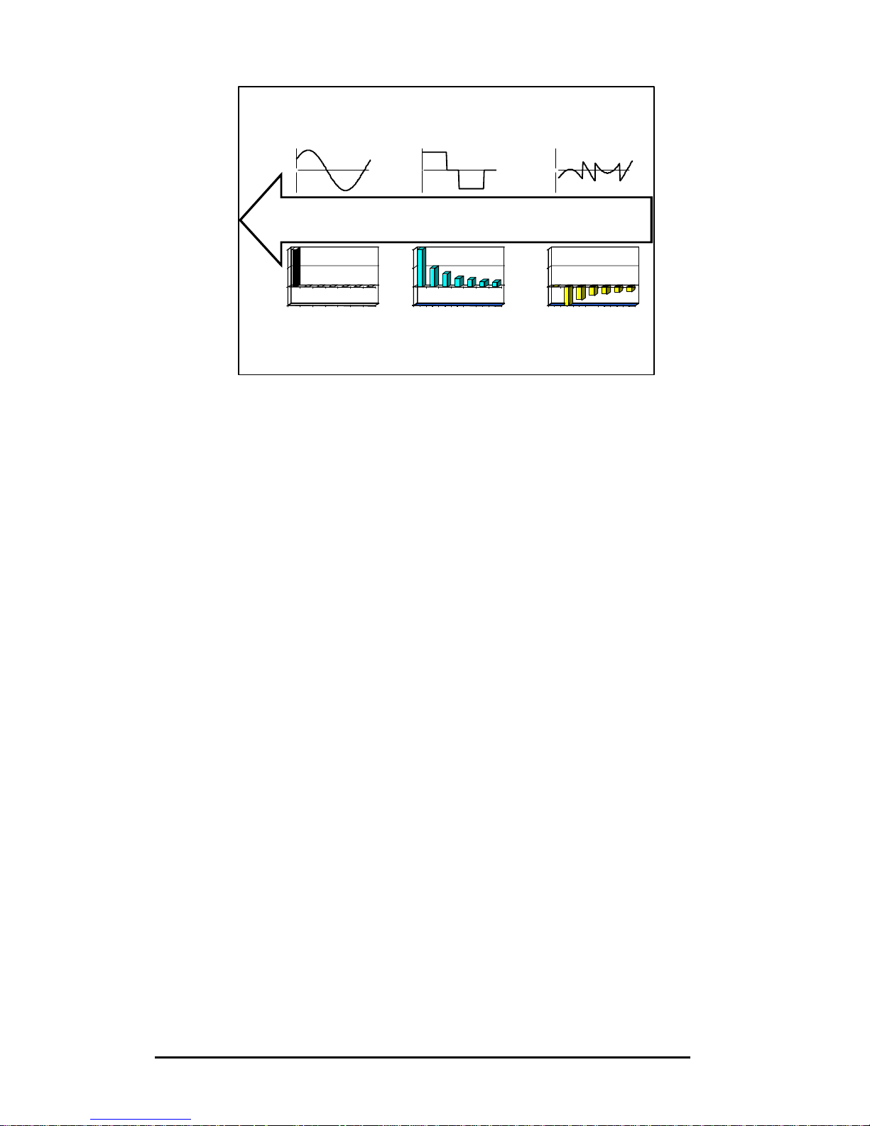
The principle of active filter showing currents and spectra is clarified in Figure
3.3.
PQFA
Supply
Load
Fundamental only
-1.3
1.3
0 360
-1.3
1.3
0 360
-1.3
1.3
0 360
i
distortion
i
compensation
Page 9
PQFA Instructions Manual
Asea Brown Boveri Jumet S.A.
9
Figure 3.3. Active filter principle illustrated in time and frequency
domains
3.3. The ABB Active filter: the PQFA.
As we have just seen, the active filter is basically a compensating current
generator. The most important parts are then the current generator and the
control system.
The compensating current is in a first step created by a three-phase Insulated
Gate Bipolar Transistors (IGBT) inverter bridge that is able to generate any
given voltage waveform with PWM (Pulse Width Modulation) technology. The
IGBT bridge uses a DC voltage source realised in the form of a DC capacitor.
The inverter bridge is in fact the same technology than in AC drives.
The generated voltage is coupled to the network via reactors and a small filter
circuit. The desired current generator is thereby achieved.
The DC capacitors are loaded actively through the inverter bridge and there is
no need of external power source. Obviously, the DC voltage level must
always be higher than the peak value of the network voltage in order to be
able to inject currents to the network.
To control the active filter the choice stands between open loop and closed
loop current control. Under open loop current control, the harmonics currents
are measured on the load side of the active filter that computes the required
compensating current and injects it into the network.
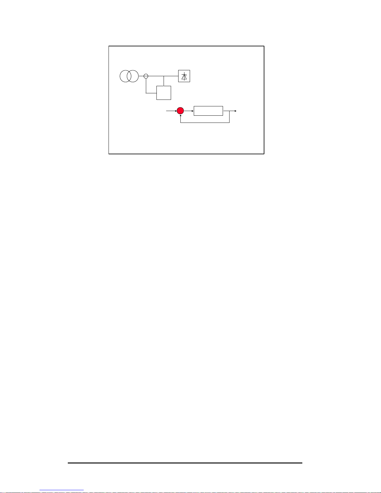
Closed loop current control as performed by the PQFA is shown in Figure 3.4.
In this topology the resulting current to the network is measured and the
active filter operates by injecting a compensating current minimising this
resulting current. In this configuration, the filter directly controls its effect on
the filtration.
+=
Load
current
1 5 7 11 13 17 19
-20
0
20
40
1 5 7 11 13 17 19
Active Filter
current
1 5 7 11 13 17 19
-20
0
20
40
1 5 7 11 13 17 19
Clean
feeder
current
1 5 7 11 13 17 19
-20
0
20
40
1 5 7 11 13 17 19
WaveformsHarmonics
-1.3
1.3
0 360
-1.3
1.3
0 360
-1.3
1.3
0 360
Page 10
PQFA Instructions Manual
Asea Brown Boveri Jumet S.A.
10
Figure 3.4. Closed loop control
In addition to being more precise, the closed loop control system also allows
for a direct control of the degree of filtering. Furthermore, the closed loop
control system ensures that measurement errors do not result in a higher
distortion.
To fully exploit the potential of an active filter we need a digital measurement
and control system that is fast enough to operate in true real time. We need to
be able to track the individual harmonics and control the compensating
current according to the requirements of the plant and this with full control at
every instant in time. To achieve this, we need advanced Digital Signal
Processors, DSP’s.
Among the physical signals needed by the PQFA, the three line currents have
obviously to be measured. Standard CTs with 5A secondary are usually
sufficient. Those analogue signals must first be acquired, levelled and
antialias-filtered before digitalisation. Fast and high precision analogue-todigital converters are used to create a digital representation of the analogue
signals. The digitised signals are then sent to the powerful DSP that controls
all measurements and calculations in real time, and builds the PWM
references for the inverter. It is another processor, a microcontroller, which
handles all digital input/output (including the command of the PWM inverter).
More dedicated to control than to calculations, this microcontroller ensures for
instance the closing of the relays and contactors.
One control is needed per PQFA system and can handle more than one
power module simultaneously.
Control
AF
Target
Measurement Feedback
Output
Page 11
PQFA Instructions Manual
Asea Brown Boveri Jumet S.A.
11
3.4. The PQFA: performances
3.4.1. Filtering
The main requirement for an active filter installed in an industrial installation is
to attenuate the harmonics produced by the non-linear loads of the
installation.
The ideal active filter should allow the user to choose freely which harmonic
components to filter and should offer an adjustable degree of filtering.
It is also worth noting that the total harmonic voltage distortion at the point of
common coupling (PCC) is often calculated up to the 40th [1] or the 50th [2]
harmonic. Furthermore, the total number of harmonics that can be filtered
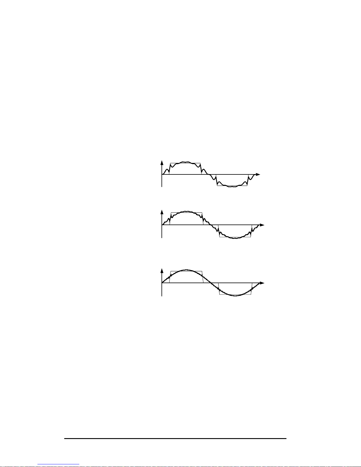
determines directly the quality of the resulting current. This is illustrated in
figure 3.5., which shows the filtered waveforms obtained by filtering up to
different harmonic levels.
(a) Filtering up to the 13th harmonic.
(b) Filtering up to the 25th harmonic.
(c) Filtering up to the 50th harmonic.
Figure 3.5. Waveforms obtained by eliminating the harmonic
components of a rectangular periodic signal up to the (a) 13th harmonic,
(b) the 25th harmonic and (c) the 50th harmonic
This figure highlights the need for an active filter that can operate up to
sufficiently high harmonic frequencies.
The PQFA can filter simultaneously 20 (15) independent harmonics up to the
50th for 50Hz (60Hz) based networks. The number of harmonics to be filtered
as well as their frequencies is completely programmable by the user.
Page 12

PQFA Instructions Manual
Asea Brown Boveri Jumet S.A.
12
Besides the harmonic selection functionality, the user has also the possibility
to specify a filtration level for each selected harmonic. The PQFA will filter the
selected harmonics until
by the user and may be different for each selected harmonic. This
functionality is especially useful when the objective is to fulfil the requirements
of a standard and results in a better use of the available compensation power.
It also allows the installation of active filters on networks already fitted with a
fixed passive filter.
We can see that we are very close to the ideal filter: the choice of which
harmonic components to filter is free and the degree of filtering is adjustable
according to the wishes of the user.
Moreover, all typical harmonics generated by three-phase non-linear loads
may be filtered simultaneously.
3.4.2. Reactive power
Besides the filtering functionality, reactive power compensation is also
possible with the active filter. Compared to traditional capacitor banks, the
reactive compensation of the PQFA is continuous (‘stepless’), fast and
smooth (no transients at switching). The compensation can be either
capacitive or inductive.
Two types of compensation are available: automatic compensation where a
target power factor has to be set, and fixed compensation based on a
predefined amount of kvar.
3.4.3. EMC
The PQFA has been verified for compliance with EU (European Union)
directives for EMC (electromagnetic compatibility) for operation at 50 Hz and
bears the CE-mark to this effect.
When an apparatus is used in a system, EU directives may require that the
system is verified for EMC compliance.
Page 13
PQFA Instructions Manual
Asea Brown Boveri Jumet S.A.
13
4. Components description and identification
4.1. Components description
As already explained, the active filter is basically composed of two parts: the
current generator and the control system.
4.1.1. PQF current generator.
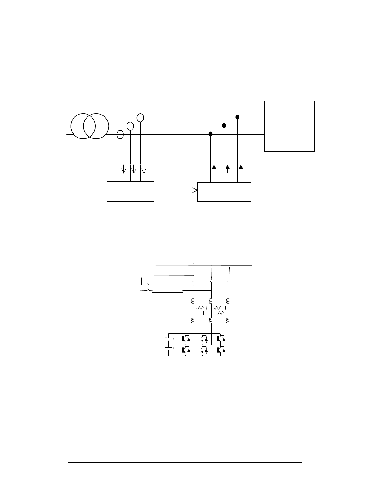
The power circuit of the ABB active filter PQF is represented hereafter.
Output
Filter
PWM inverter
Main Breaker
Power
Lines
+
-
PWM Reactors
Preload
The main components are:
- PWM inverter
- PWM reactors
- Output filer
- Preloading circuit
The current generator is physically organised in power modules, each
including a PWM inverter, three PWM reactors and the output filter.
Each PQFA cubicle may contain one or two power modules. There is one
breaker and one preloading circuit per cubicle.
Non-linear load(s)
(three-
phase or
single-phase)
PQF Digital
Control
Compensation
current
Current
measurement
PQF current
generator
Page 14
PQFA Instructions Manual
Asea Brown Boveri Jumet S.A.
14
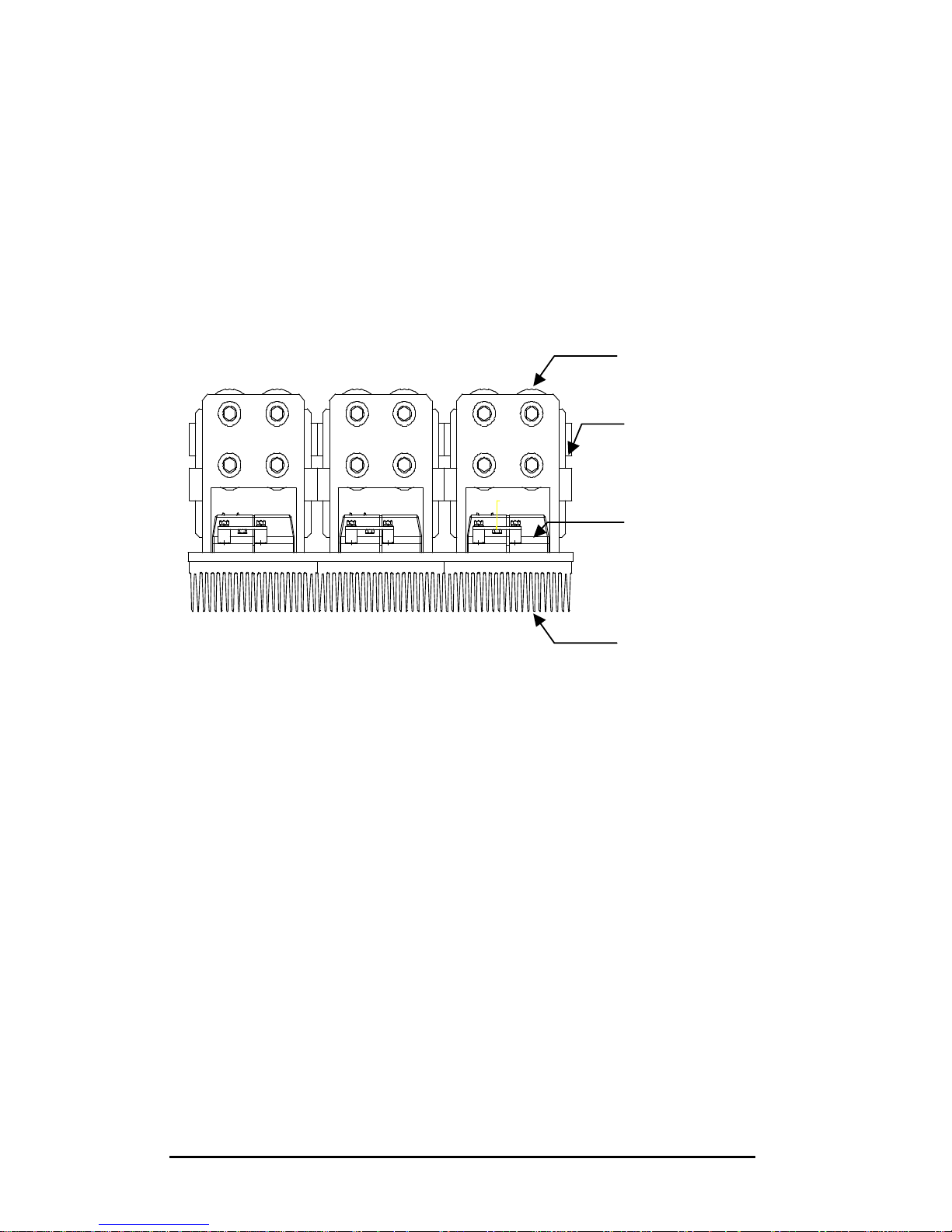
The PWM inverter is composed of DC capacitors and an IGBT inverter bridge.
This system is able to generate any voltage waveform with PWM technology.
The physical layout of a PWM inverter module is shown hereafter. Each PWM
inverter is fitted with a local electronic control called the domino board. The
domino board is controlled by the central DSP. The domino board is fitted with
jumpers noted JP100, JP101, JP102, JP103, JP104, JP105, JP106, JP109
and JP110 (JP107 and JP108 are off). In case of several power modules, only
the domino board of the last slave is fitted with jumpers.
The PWM reactors convert the voltage created by the PWM inverter into
currents that will be injected in the network.
The output filter consists in line reactors and an RC shunt circuit.
The function of the preloading circuit is to avoid at start-up high inrush
currents that could damage the power electronics or create transients in the
network.
4.1.2. The control
For best performances, the control of the PQFA is Digital Signal Processor
(DSP) based.
The three lines currents are measured by external CT. Those analogue
signals must first be acquired, levelled and antialias-filtered before
digitalisation. Fast and high precision anlogue-to-digital converters are used to
create a digital representation of the analogue signals. The digitised signals
are then sent to the powerful DSP that controls all measurements and
DC capacitors
Low inductance
DC bus bar
Inverter
Heatsink
Page 15
PQFA Instructions Manual
Asea Brown Boveri Jumet S.A.
15
calculation in real time, and builds the PWM references for the inverter. It is
another processor, a microcontroller, which handles all digital input/output
(including the command of the PWM inverter). More dedicated to control than
to calculations, this microcontroller ensures for instance the closing of relays
and contactors.
One control unit may command up to 8 power modules.
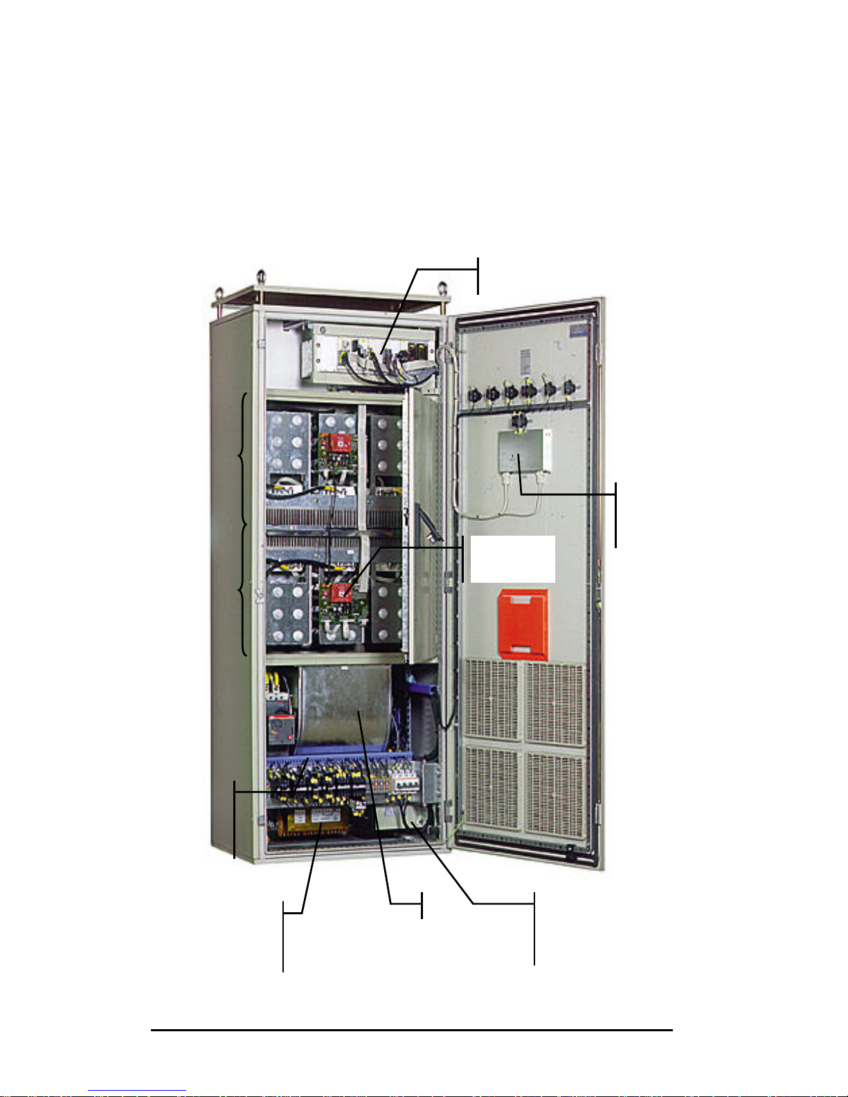
4.2. Components identification
Control
PWM
inverter
module 2
PWM
inverter
module 1
Domino
board
Circuit
breaker
Fan
Output
filter
capacitor
Auxiliary
voltage
transformer
PQF
Manager
Page 16

PQFA Instructions Manual
Asea Brown Boveri Jumet S.A.
16
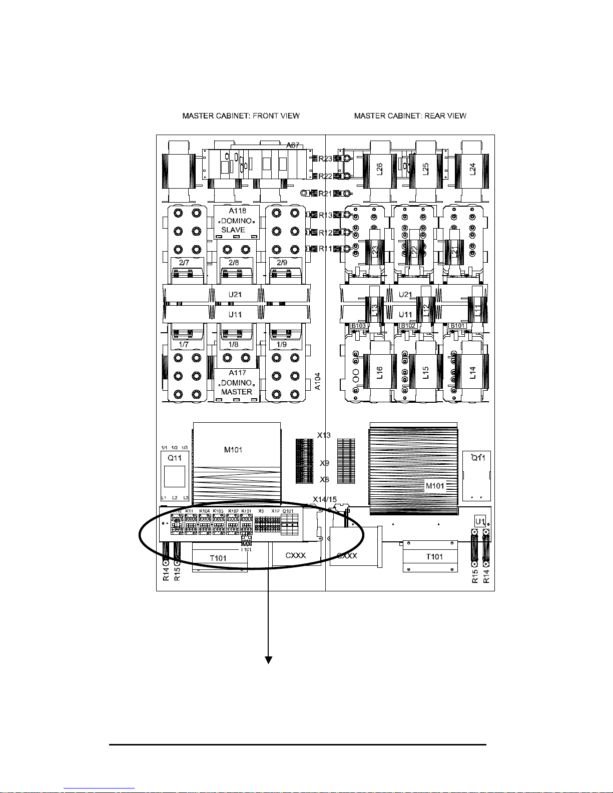
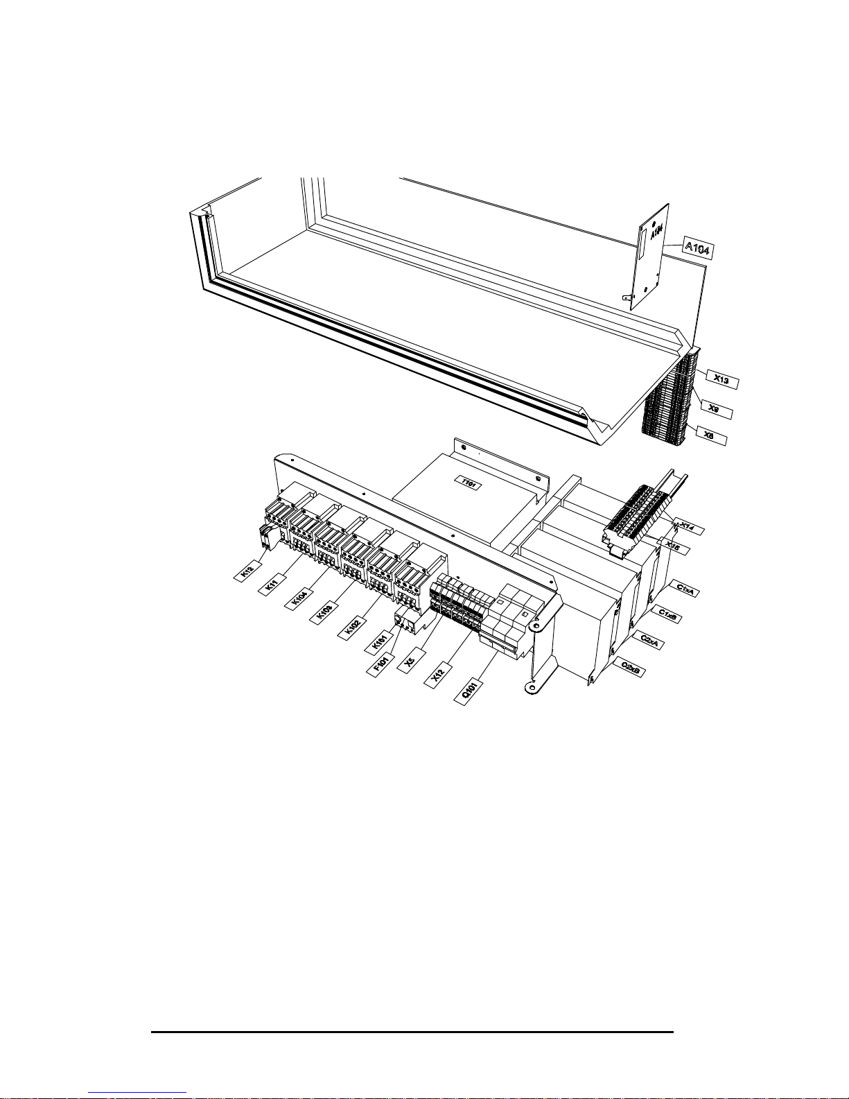
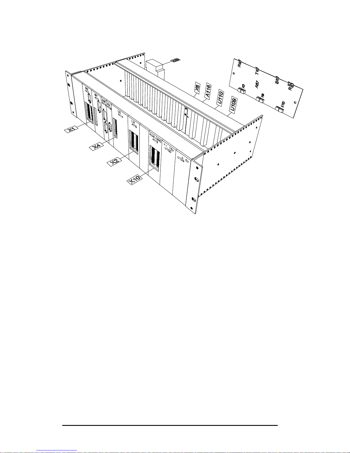
A more detailed identification is given in the following pages.
The identification hereafter is related to the drawings of the following pages.
Internal views indicate the position of identified components but fixation
details are not included. Although visible on the drawings, some components
may actually be hidden in the real structure.
Mains power breaker
Q11: power breaker
L1, L2, L3: power cables connection
K102: contactor closing MCB
K103: contactor opening MCB
X8: terminal Sace wiring
Fan
M101: fan motor
K101: fan contactor
X9: terminal block motor connection wiring
F101: motor overload protection
Auxiliaries
Q101: breaker for auxiliaries
T101: auxiliary voltage transformer
PWM inverter
U11: module 1
U21: module 2
A117: module 1 domino board
A118: module 2 domino board
Output filter
C11_12_13A/B Module 1 output filter capacitor
C21_22_23A/B Module 2 output filter capacitor
X14 Terminal block capacitors module 1 wiring
X15 Terminal block capacitors module 2 wiring
R11/12/13 Module 1 output filter resistor
R21/22/23 Module 2 output filter resistor
L11/12/13 Module 1 line reactors
L21/22/23 Module 2 line reactors
PWM reactors
L14/15/16 Module 1 PWM reactors
L24/25/26 Module 2 PWM reactors
Page 17

PQFA Instructions Manual
Asea Brown Boveri Jumet S.A.
17
Preloading circuit
K11 Preload contactor
R14/15 Preload resistor
U1 Preload bridge
Control rack
A111 Digital I/O board
A112 Interface board – IGBT’s and DSP
A113 Digital Signal Processor
A119 Interface PQF Manager board
A114 Current input board
A115 Analog input board
A116 +24V power supply board
U100 Power supply ? 15V
U109 Power supply + 5V
X1 Terminal block digital I/O wiring
X4 Terminal block current input wiring
X2 Terminal block analog input wiring
X10 Terminal power supply wiring
X6 Terminal current input wiring
A67 AC voltage board
Door components
S102 RESET push button
S101 RUN push button
S104 Remote local switch
H101 White lamp: controller connected to supply (auxiliary
breaker closed)
H102 Red lamp: MCB closed
H103 Green lamp: MCB open
A120 PQF-Manager
Other components
B101/102/103 Internal current sensors
K104 Alarm contactor
K12 Remote contactor
X5 Terminal block backplane wiring (external CT connection)
Page 18

PQFA Instructions Manual
Asea Brown Boveri Jumet S.A.
18
X10 Terminal power supply wiring
X11 Terminal DC bus wiring
X12 Terminal signaling wiring
X13 Terminal inter cubicles wiring
A104 DC voltage convertor
Page 19
PQFA Instructions Manual
Asea Brown Boveri Jumet S.A.
19
Master cubicle view
Zoom on next page
Page 20
PQFA Instructions Manual
Asea Brown Boveri Jumet S.A.
20
Page 21
PQFA Instructions Manual
Asea Brown Boveri Jumet S.A.
21
Control rack details
Page 22
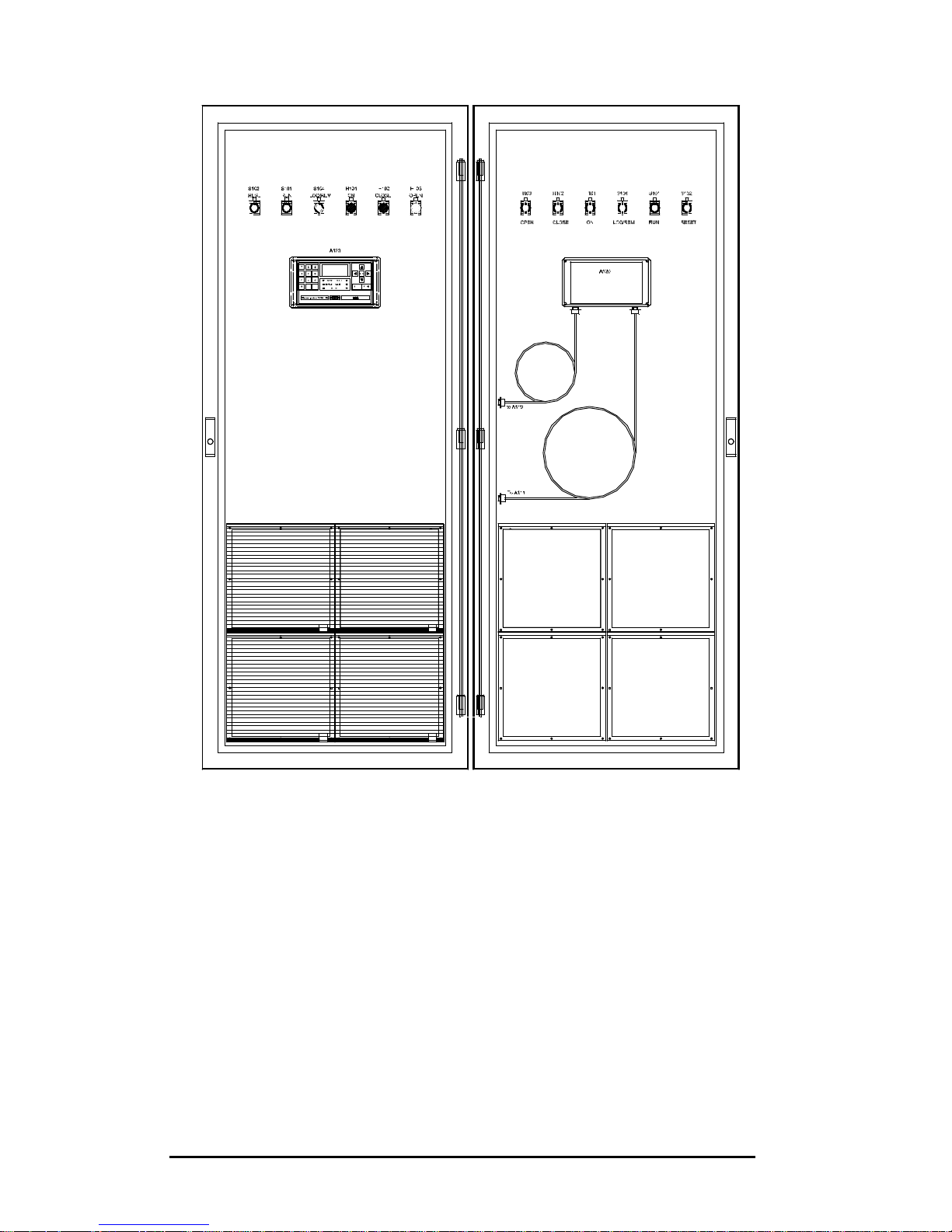
PQFA Instructions Manual
Asea Brown Boveri Jumet S.A.
22
Master cubicle door view
Page 23
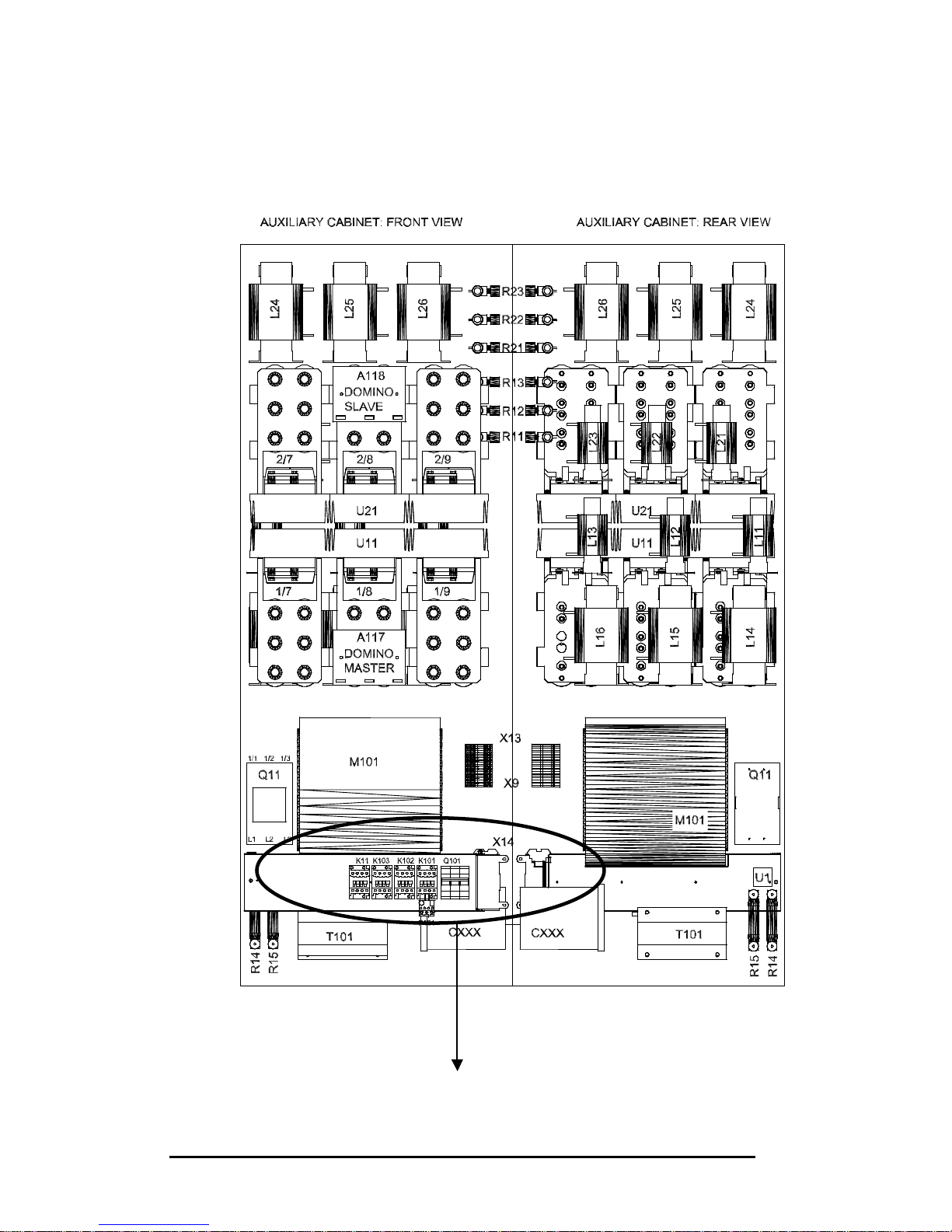
PQFA Instructions Manual
Asea Brown Boveri Jumet S.A.
23
Auxiliary cubicle view
Zoom on next page
Page 24
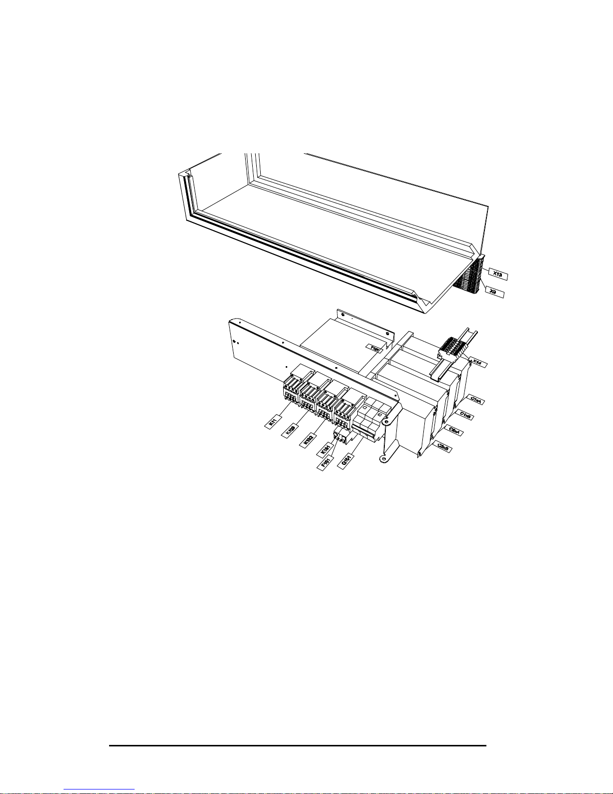
PQFA Instructions Manual
Asea Brown Boveri Jumet S.A.
24
Page 25
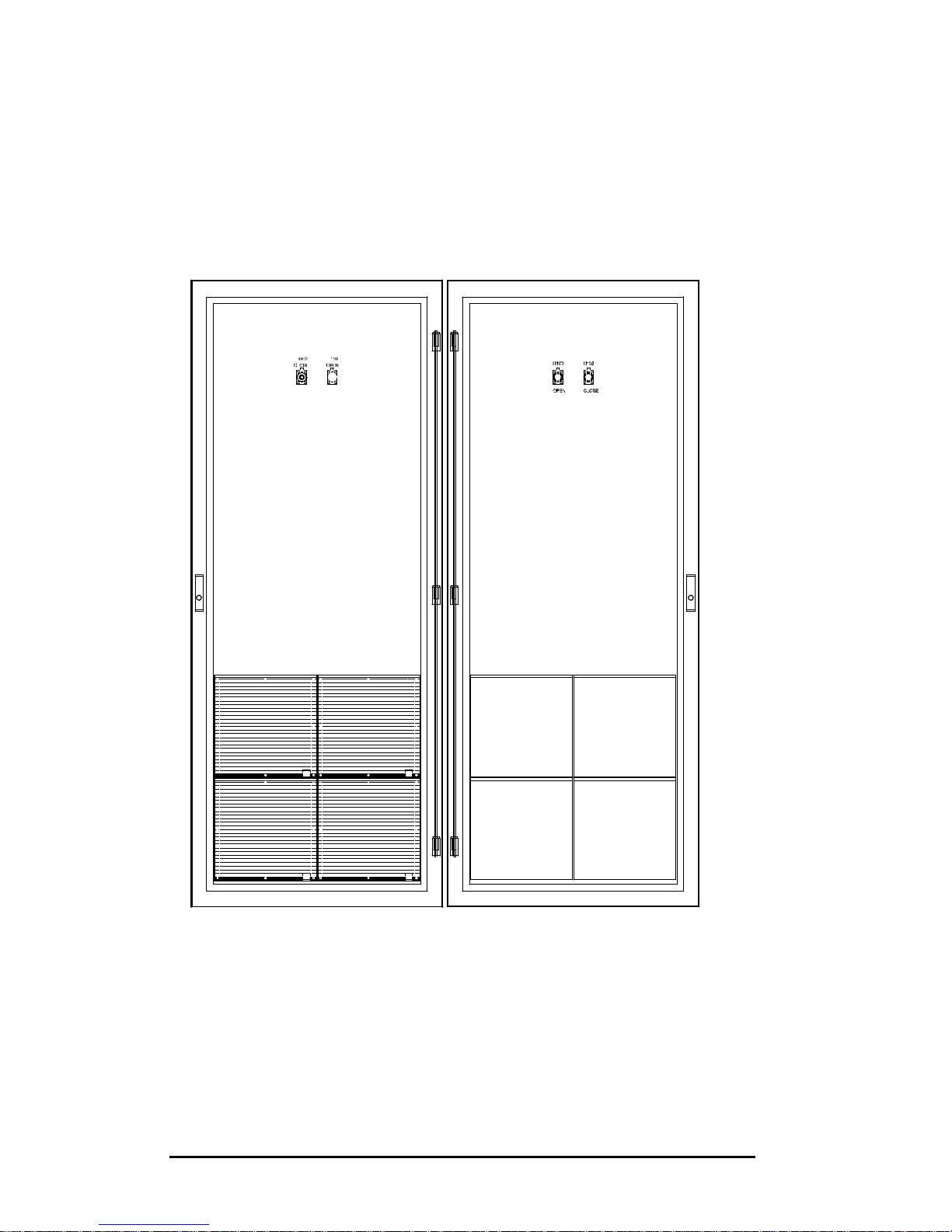
PQFA Instructions Manual
Asea Brown Boveri Jumet S.A.
25
Slave cubicle door view
Page 26
PQFA Instructions Manual
Asea Brown Boveri Jumet S.A.
26
5. Mechanical installation
The PQFA is suitable for indoor installation, on firm foundations, in a wellventilated area without dust and excessive aggressive gases where the
ambient parameters do not exceed the following values:
40°C max;
30°C (average temperature) over 24 hours;
Minimum temperature: +5 °c
Humidity less than 95% RH non-condensing
Altitude: max. 1000m without derating.
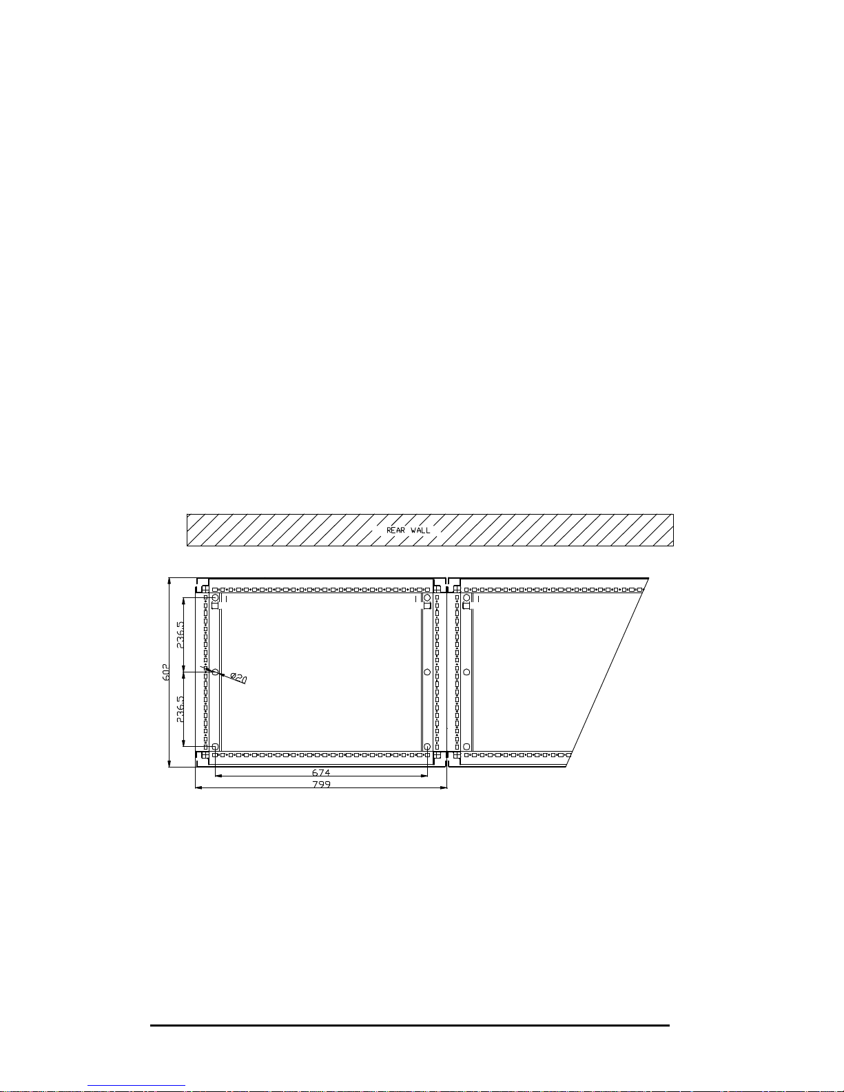
For units with nominal voltage above 415V, the rear side of the cubicles must
be located at least at 100mm from the wall as represented in the sketch
hereunder.
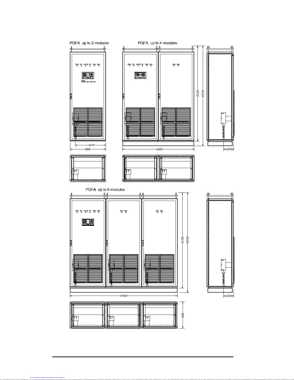
PQFA cubicles have standard dimensions of 800 x 600 x 2150 mm (width x
depth x height).
Each cubicle may contain one or two power modules and is fitted with its own
bottom cable entry and breaker.
For systems with more than 2 power modules, cubicles are installed on a
common base of 100-mm height. Standard dimensions for PQFA with up to 6
power modules are shown on page 26.
PQFA#1 PQFA#2
PQFA#1 PQFA#2
At least 100mm spacing must be provided between PQFA rear side and wall
Page 27
PQFA Instructions Manual
Asea Brown Boveri Jumet S.A.
27
For PQFA with top cable entry, an additional cubicle for cable connection is
added.
CAUTION
The PQFA dissipates significant amounts of heat that have to be evacuated
out of the room where the filter is located. Otherwise, you may experience
excessive temperature rise.
For proper cooling of the PQFA, a minimum airflow of 6000 m3/h of cooling air
has to be supplied to the each fan of the unit. Please ensure the air used for
cooling is regularly renewed and does not contain conductive particles,
significant amounts of dust, or corrosive or otherwise harmful gases.
The cooling air intake temperature cannot exceed 40°C under any operating
condition.
The hot exhaust air has also to be properly ducted away.
Page 28
PQFA Instructions Manual
Asea Brown Boveri Jumet S.A.
28
Page 29

PQFA Instructions Manual
Asea Brown Boveri Jumet S.A.
29
6. Electrical installation
Your PQFA is a parallel active filter: it is installed in parallel with the load(s).
Connection implies:
?? 3 power cables
?? 3 CT (one per phase)
?? 6 control wires for the CT
?? Ground/PE
6.1. Overvoltage
The PQFA is able to withstand continuously an overvoltage (inclusive of
harmonics but not transients) of up to 110 % of the rated voltage. Higher
voltages than the rated one would imply an operation at limited power of the
filter. Since operation at the upper limits of voltage and temperature may
reduce its life expectancy, the PQFA should not be connected to systems for
which it is known that the overvoltage will be sustained indefinitely.
6.2. Power cables and external protection
Each cubicle is fitted with its own circuit breaker (bottom cable entry) and
needs to be individually connected to the supply.
The power cable size should be rated on the basis of X times the nominal
current of the corresponding cubicle (one or two power modules) where X is a
multiplication factor which allows to take into account the skin effect.
This multiplication factor is the result of an iterative calculation and can be
determined by means of the following process:
Important remark: please note that the following process is made to take into
account the skin effect only. Other deratings due to local standards and/or
installation conditions (as e.g. cables proximity, number of cables connected
in parallel,…) have to be taken into account by the company responsible for
the PQF cable connection.
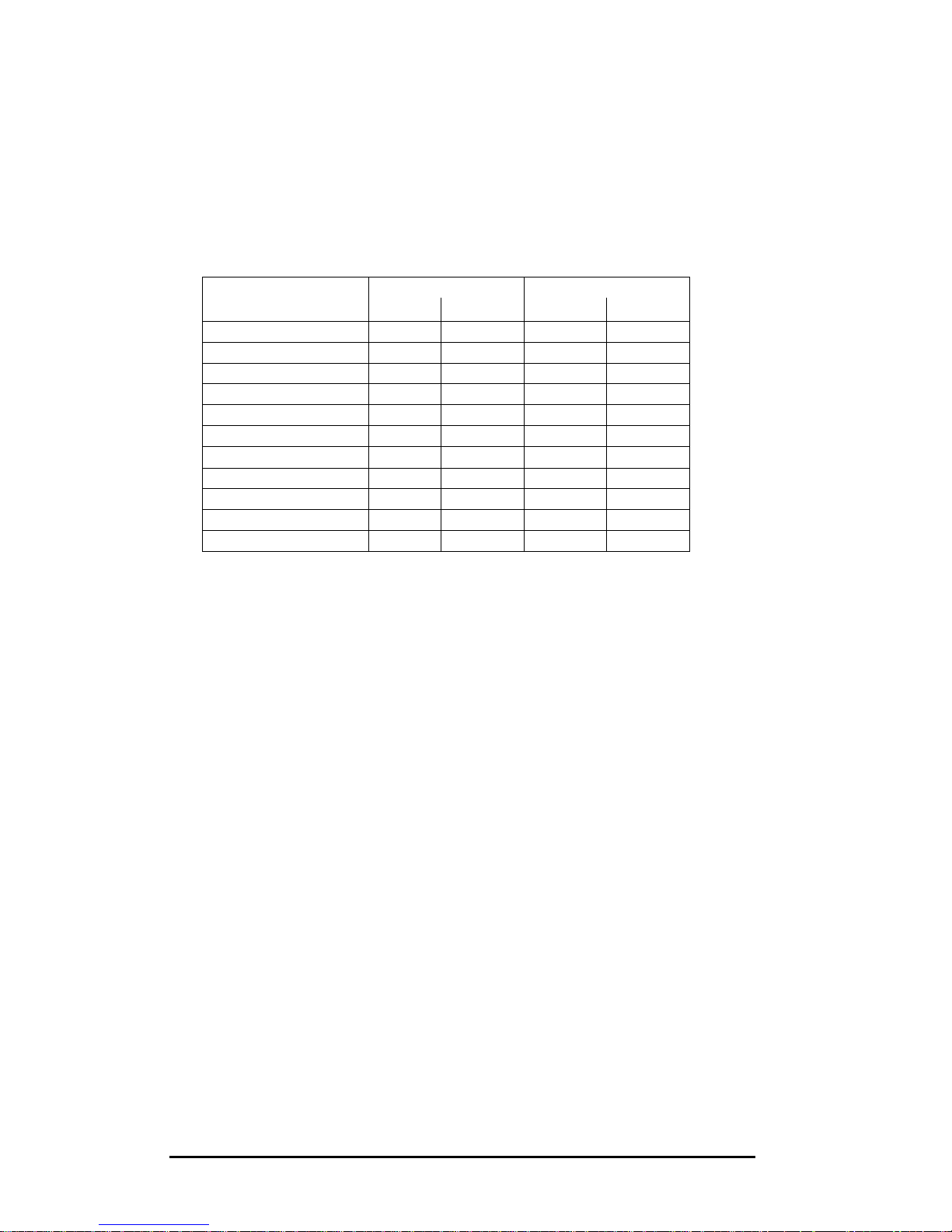
Step 1: as initial value of this iterative process, determine the preliminary
cable section on the basis of the nominal current.
Step 2: based on the previously determined cable section, find in the table
here below the multiplication factor that must be applied.
Step 3: determine the cable section on the basis of the value of the
multiplication factor times the nominal current.
- if the cable section found is equal to the previously found cable section,
the process can be stopped.
The cable section is then determined taking into account the skin effect.
(see examples below)
Page 30
PQFA Instructions Manual
Asea Brown Boveri Jumet S.A.
30
- If the cable section found is bigger than the previously found value, step 2
and 3 have to be repeated until the cable sections are equal (see example
below).
Remark: during this process, it can be found that more than one cable per
phase is needed. The process has then to be applied on each cable as shown
in the example n°3 below.
SSeeccttiioonn
50Hz 60Hz
[mm2]
Al Cu Al Cu
16 1.01 1.01 1.01 1.01
25 1.01 1.02 1.01 1.03
35 1.02 1.03 1.02 1.04
50 1.03 1.06 1.04 1.08
70 1.05 1.1 1.06 1.13
95 1.08 1.16 1.10 1.21
120 1.11 1.30 1.15 1.30
150 1.16 1.30 1.21 1.39
185 1.22 1.41 1.28 1.50
240 1.31 1.55 1.40 1.66
300 1.41 1.70 1.52 1.84
Table: Multiplication factors for different cable types
Examples:
Please note that the following examples are given for information only
(see important remark above).
Example n°1:
PQF-L 80A 480V 60hz
Step 1: IN = 80A ? cable section (*) = 25 [mm2]
Step 2: multiplication factor for a 25 [mm2] copper cable at 60hz = 1.03
Step 3: I = IN x 1.03 = 80A x 1.03 = 83 A
Step 4: I = 83A ? cable section (*) : 25 [mm2]
This section is equal to the section found in the previous step.
Result : one copper cable of 25 [mm2] per phase
Page 31

PQFA Instructions Manual
Asea Brown Boveri Jumet S.A.
31
Example n°2:
PQFA-A 155A 480V 60hz
Step 1: IN = 155A ? cable section (*) = 70 [mm2]
Step 2: multiplication factor for a 70 [mm2] copper cable at 60hz = 1.13
Step 3: I = IN x 1.13 = 155A x 1.13 = 175 A
Step 4: I = 175A ? cable section (*) : 95 [mm2]
Step 5: multiplication factor for a 95 [mm2] copper cable at 60hz = 1.21
Step 6: I = IN x 1.21 = 155A x 1.13 = 187,5 A
Step 7: I = 187,5A ? cable section (*) : 95 [mm2]
This section is equal to the section found in the previous step.
Result : one copper cable of 95 [mm2] per phase
Example n°3:
PQFA-B 427A 400V 50hz
Step 1: IN = 427A ? cable section (*) = 300 [mm2]
Step 2: multiplication factor for a 300 [mm2] copper cable at 50hz = 1.70
Step 3: I = IN x 1.70 = 427 A x 1.70 = 726 A
Step 4: I = 726A ? cable section (*) : 2 x 185 [mm2]
Step 5: multiplication factor for a 185 [mm2] copper cable at 50hz = 1.41
Step 6:
I = IN x 1.41 = 427A x 1.41 = 602 A ? which means 301 A per cable
Step 7: I= 301 A ? cable section (*) : 185 [mm2]
This section is equal to the section found in the previous step.
Result : two copper cable of 185 [mm2] per phase
(*) given for information only.
Page 32
PQFA Instructions Manual
Asea Brown Boveri Jumet S.A.
32
If single core cables are used an alloy gland plate is recommended.
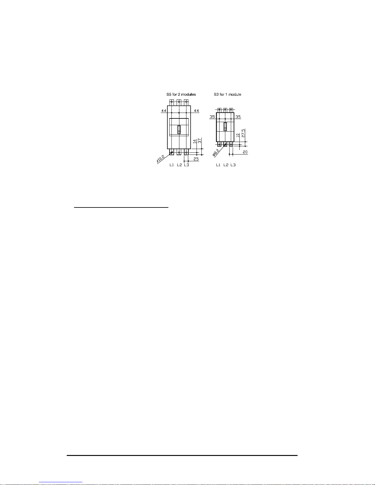
Cable terminals dimensions are shown hereafter.
6.3. Current transformers/control cables selection
Three CT’s are needed since the PQFA monitors the three phases of the
network.
The proper operation of the PQFA does not require any special CT’s. The
requirements are minimum:
?? 5A of secondary
?? 15 VA minimum for up to 30 meters of 2.5 mm² cable
?? Class 1 accuracy or better
?? Ratio limit above maximum line current
In case the CT’s are shared with other loads, the VA burden shall be adapted
and the connection of the different loads (including the PQFA) must be in
series.
Twin 2.5 mm² control cable is the most suitable for this application.
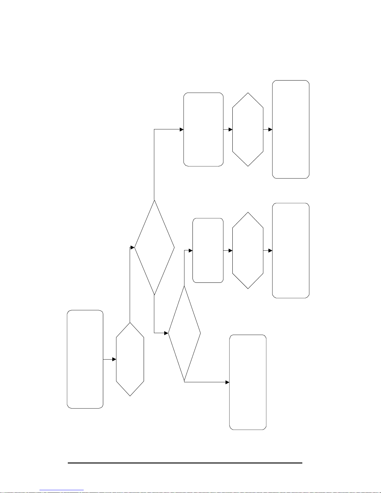
In order to determine the suitable CT’s for your application, please refer to the
following chart.
Note for top cable entry PQFA
: if you filter is fitted with an additional cubicle
for top cable entry, you only need one s
et of 3 power cables to be connected
to the busbar installed in the connection cubicle. Those cables shall be sized
as described at the beginning of this paragraph.
Page 33
PQFA Instructions Manual
Asea Brown Boveri Jumet S.A.
33
Maximum rms current of the
downstream loads (including starting
current of DC drives):
X1 = ….. Arms
Multiply X1 by
1.6:
X2 = …. Arms
CT cables > 30 meters ?
Select 3 identical CT’s such that:
- rating at primary ? X2
- rating at secondary: 5A
- Burden ? 15 VA
- Class 1 accuracy or better
NO
Section of CT cables:
2.5 mm²? (recommended)
Determine the length of
CT cables (meters)
L = … m
X3 = (L x 0.007 x 25) + 10
X3 = … VA
Select 3 identical CT’s such that:
- rating at primary ? X2
- rating at secondary: 5A
- Burden ? X3 VA
- Class 1 accuracy or better
Determine the length (m) and
resistance (? /m)of
CT cables (meters)
L = … m
R = … ? /m
X4 = (L x R x 25) + 10
X4 = … VA
Select 3 identical CT’s such that:
- rating at primary ? X2
- rating at secondary: 5A
- Burden ? X4 VA
- Class 1 accuracy or better
NOYES
YES
Page 34
PQFA Instructions Manual
Asea Brown Boveri Jumet S.A.
34
6.4. Current transformers installation
Special care has to be taken for the connection and location of the CT’s: it is
the most current source of problems occurring at commissioning stage.
WARNING: when connecting the CT’s to the PQFA, the secondaries of
the CT’s have to be short-circuited.
First of all, the CT’s have to be positioned for closed loop control: they have to
monitor the resulting current after filtering.
The CT’s must also be positioned in the correct direction around the power
cable: the K (or P1) side should be in the direction of the supply and the L (or
P2) side should be in the direction of the load.
6.4.1. CT’s connection to the PQFA
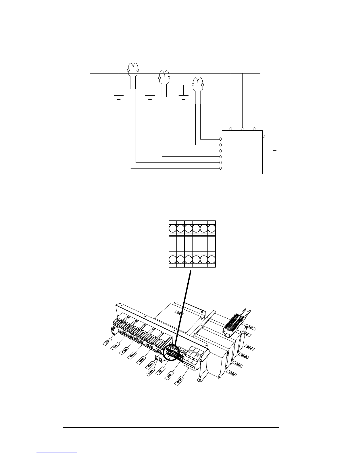
The connections between the CT’s and the filter must satisfy the following
scheme:
?? The k terminal of line 1 CT is connected to terminal X5-1 of the filter
?? The l terminal of line 1 CT is connected to terminal X5-2 of the filter
?? The k terminal of line 2 CT is connected to terminal X5-3 of the filter
?? The l terminal of line 2 CT is connected to terminal X5-4 of the filter
?? The k terminal of line 3 CT is connected to terminal X5-5 of the filter
?? The l terminal of line 3 CT is connected to terminal X5-6 of the filter
Page 35
PQFA Instructions Manual
Asea Brown Boveri Jumet S.A.
35
L1
L2
L3
Load sideSupply side
K L
k l
K L
k l
K L
k l
PQF
X5.2
X5.3
X5.4
X5.5
X5.6
X5.1
L1 L2 L3
X5
Page 36
PQFA Instructions Manual
Asea Brown Boveri Jumet S.A.
36
6.4.2. CT’s connection topology: cases
The location of the CT’s is critical to ensure the proper operation of the active
filter. The CT’s are the “eyes” of the filter and it will react in accordance with
the information supplied by them.
The location of the CT’s must always be in closed loop configuration. This
means that the CT’s must see the load current and the filter current.
In some cases, summation CT’s might be needed to fulfil the closed loop
requirement.
Typical circuit topologies and adequate CT’s location are described hereafter
in the following order:
Case 1: Global compensation – one feeding transformer.
Case 2: Individual compensation – one feeding transformer.
Case 3: Global compensation – transformer busbar not accessible.
Case 4: Two independent feeding transformers.
Case 5: Back up generator.
Please bear in mind that the active filter always needs 3 CT’s: one per phase.
66..44..22..11.. CCaassee 11:: GGlloobbaall ccoommppeennssaattiioonn –– oonnee ffeeeeddiinngg ttrraannssffoorrmmeerr
This is the most frequent configuration: one transformer feeds several nonlinear loads. The active filter is installed in central position and filters the
combined harmonic currents.
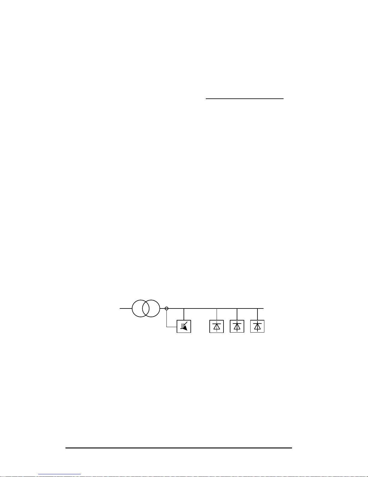
This configuration and the proper location of the CT’s is represented
hereafter.
Figure 6.1. Global compensation – one feeding transformer.
PQF
LOAD LOAD LOAD
Page 37
PQFA Instructions Manual
Asea Brown Boveri Jumet S.A.
37
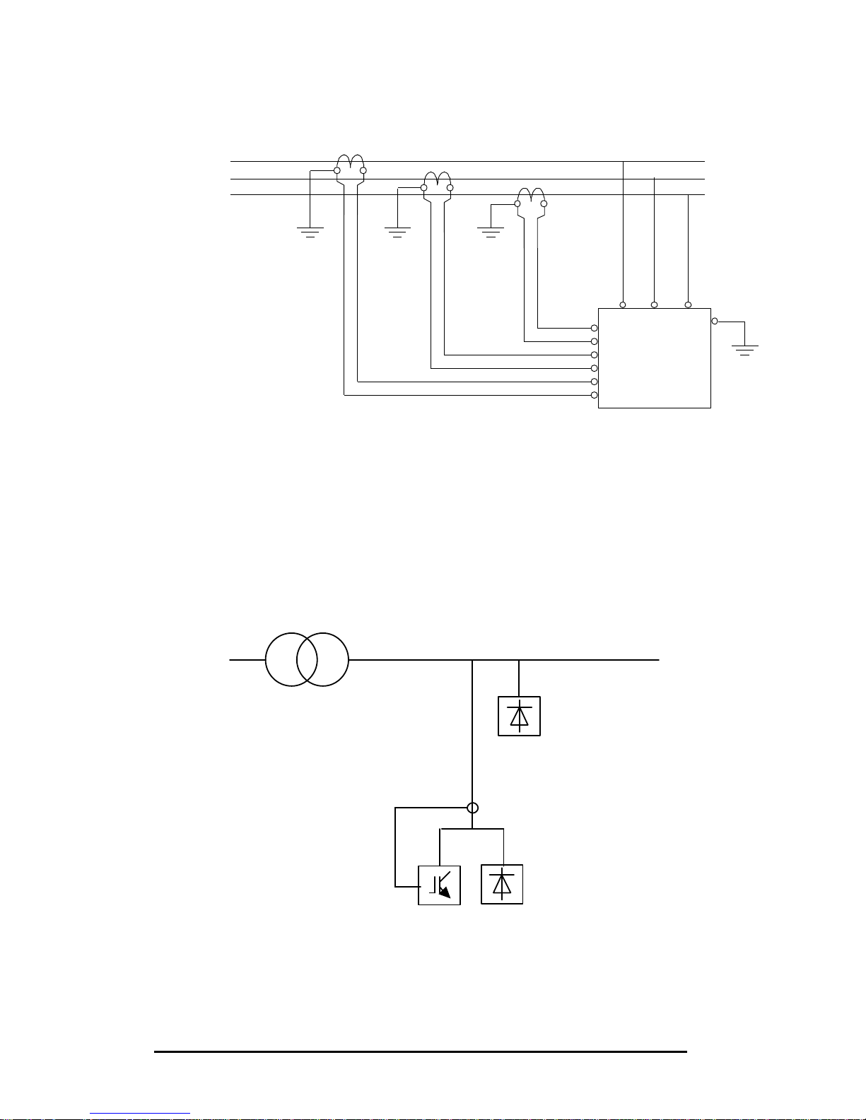
The connection of the CT’s to the active filter must be as represented herafter:
L1
L2
L3
Load sideSupply side
K L
k l
K L
k l
K L
k l
PQF
X5.2
X5.3
X5.4
X5.5
X5.6
X5.1
L1 L2 L3
Figure 6.2. CT’s connection to the active filter.
66..44..22..22.. CCaassee 22:: IInnddiivviidduuaall ccoommppeennssaattiioonn –– oonnee ffeeeeddiinngg ttrraannssffoorrmmeerr
Instead of installing one active filter in central position, it also possible to
connect the active filter and its CT’s so that it compensates one particular load
only.
In the example hereafter, the active filter PQF is connected to compensate
Load 1 only. It does not see load 2.
Figure 6.3. Individual compensation – one feeding transformer
The connection of the 3 CT’s to the active filter is described in 6.4.1.
LOAD 2
LOAD 1
PQF
K = P1, L = P2, k = S1, l = S2
Page 38
PQFA Instructions Manual
Asea Brown Boveri Jumet S.A.
38
66..44..22..33.. CCaassee 33:: gglloobbaall ccoommppeennssaattiioonn –– ttrraannssffoorrmmeerr bbuussbbaarr nnoott aacccceessssiibbllee..
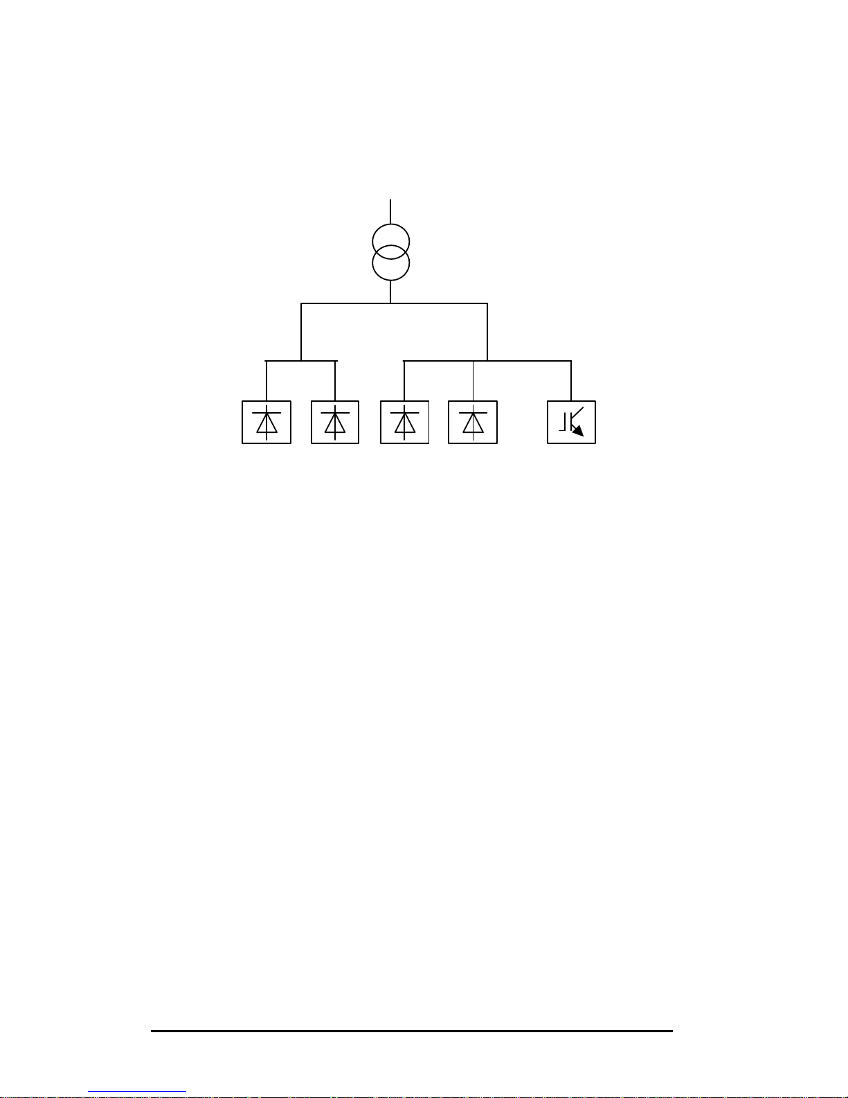
The active filter is required to filter the loads of side A and side B but the
transformer busbar not being accessible, the CT’s cannot be installed in
central position.
Figure 6.4. Transformer busbar with no access: single-line diagram
For this configuration, three CT’s (one per phase) have to be installed on side
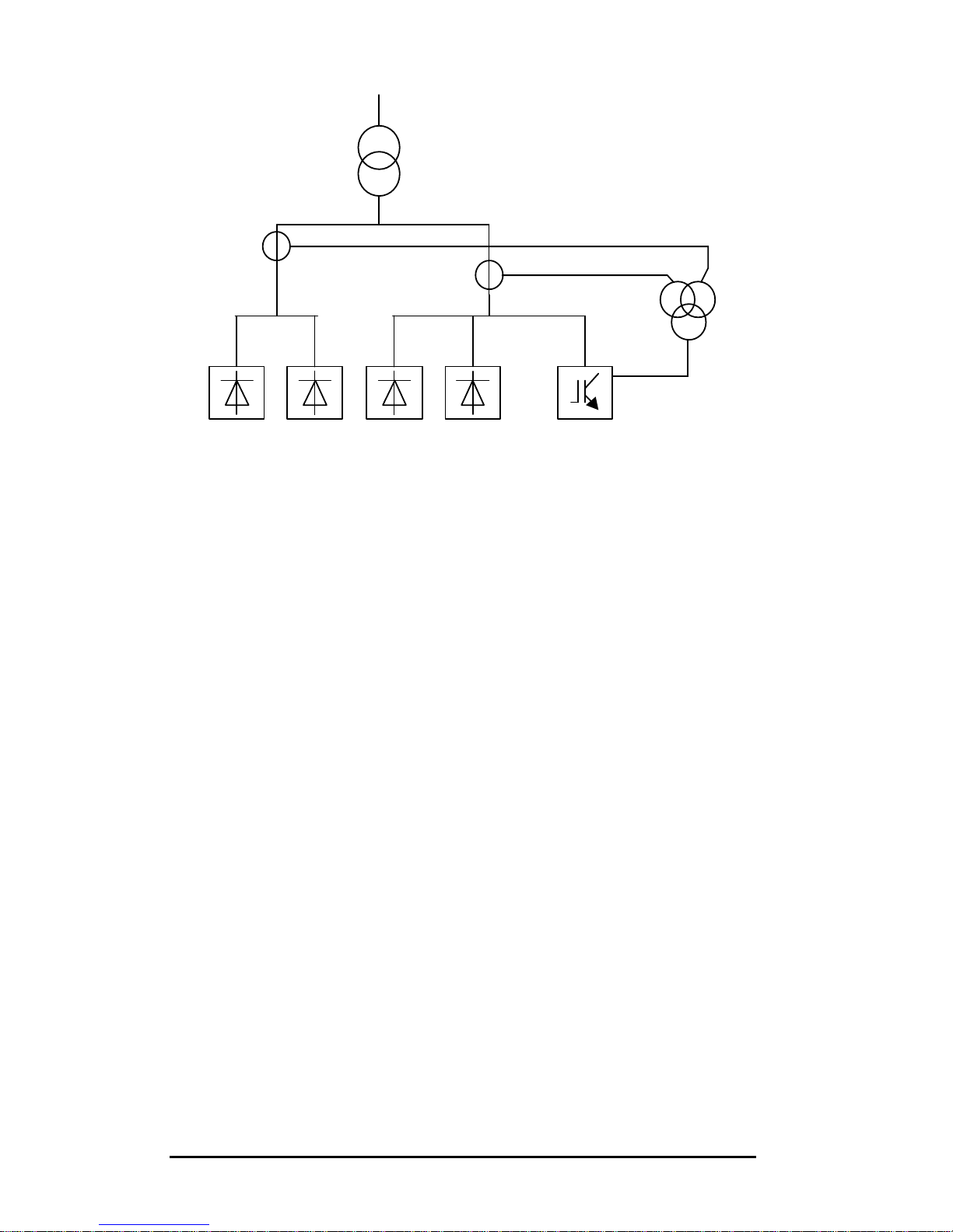
A et on side B (in total, 6 CT’s). Those CT’s will then feed 3 summation CT’s
(one per phase) that are connected to the active filter. This CT topology is
represented in figure 6.5.
LOADS
(Side A)
LOADS
(Side B)
PQF
Page 39
PQFA Instructions Manual
Asea Brown Boveri Jumet S.A.
39
Figure 6.5. Transformer busbar with no access: CT connection (to be
done for each phase)
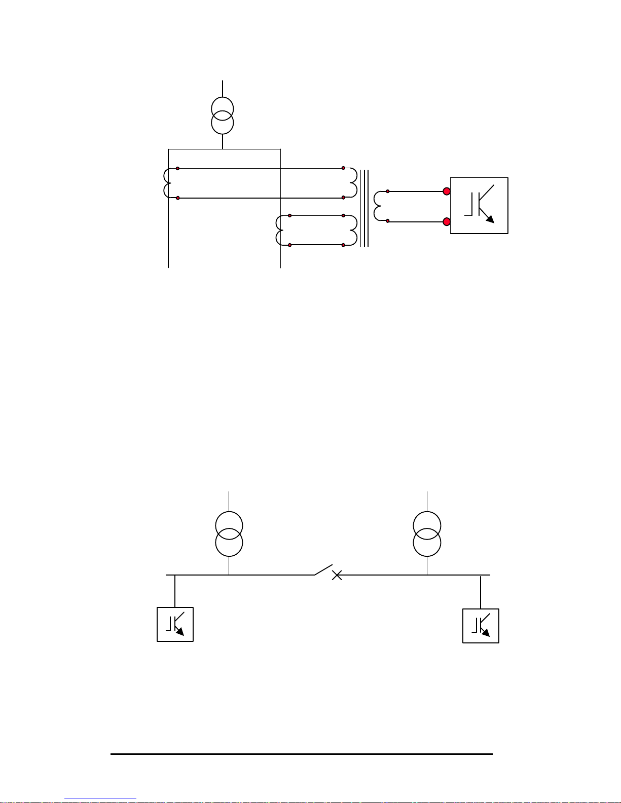
The CT’s installed in each phase of side A et B (CT1 and CT2) must be
identical (X / 5) and feed a summation CT whose secondary is 5A (5+5/5A).
The summation CT is then connected to the active filter in accordance with
chapter 6.4.1.
A total of 3 summation CT’s (one per phase) must be used. The CT ratio to be
programmed in the filter is: 2X / 5.
The CT – summator – PQF connection is represented here below. This has
to be done for each phase.
LOADS
(Side A)
LOADS
(Side B)
PQF
Su
mmation CT
(one per phase)
Primary 1: 5 A
Primary 2: 5A
Secondary: 5A
CT 1 (one per
phase)
Primary: X
Secondary: 5A
CT 2 (one per
phase)
Primary: X
Secondary: 5A
Page 40
PQFA Instructions Manual
Asea Brown Boveri Jumet S.A.
40
Figure 6.6. Connection between CT1, CT2 , the summation CT and PQF
for one phase.
66..44..22..44.. CCaassee 44:: ttwwoo iinnddeeppeennddeenntt ffeeeeddiinngg ttrraannssffoorrmmeerrss..
Two independent transformers (the tie is normally open) feeds two different
set of loads. One active filter is fitted on each LV busbar.
This system may however also work in degraded mode: the tie is closed and
only one transformer feeds the whole LV system.
By connecting the CT’s as described hereafter, it is still possible to filter
properly the harmonics and to correct the power factor.
Figure 6.7. Two independent transformers: single-line diagram
PQF
PQF
T1 T2
S1, k
S2, l S1, k
S2, l
P1 P2 P1 P2
S1
S2
k
l
PQF
Side A
Side B
P1, K
P2, L
P1, K
P2, L
Page 41
PQFA Instructions Manual
Asea Brown Boveri Jumet S.A.
41
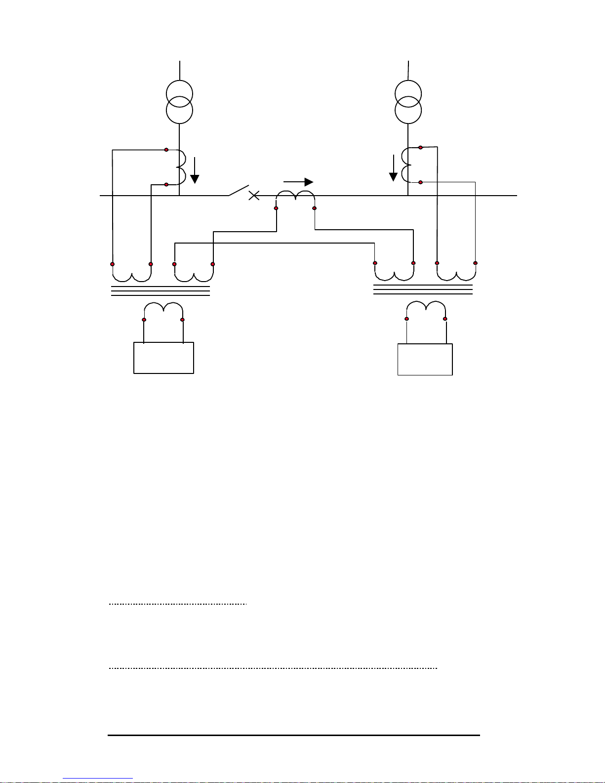
Figure 6.8. Two independent transformers: CT connection for one
phase.
For each phase, 3 CT’s must be installed: - one to measure I1
- one to measure I2
- one to measure I0.
Those CT’s must be identical: X/5 A.
CT I1 and CT I0 feed a summation CT which is connected to PQF1.
CT I2 and CT I0 feed a summation CT which is connected to PQF2.
Those summation CT’s must be 5+5 / 5 A.
Condition 1: the tie is open.
PQF1 sees I1 and PQF2 sees I2 (I0 = 0). The two transformers work
independently and the total current to be compensated is I1 + I2.
Condition 2: the tie is closed but both transformers feed the loads.
In this configuration, PQF1 sees (I1-I0) and PQF2 sees (I2+I0). The total
current seen by the two filters is I1 + I2.
S1, k
S2, l
P1
P2 P1
P2
S1 S2
S1, k
S2, l
S1
k
S2
l
P1 P2
P1
P2
S1
S2
I1 I2
I0
I’1-I’0
PQF 1
I’2+I’0
PQF 2
k l k l
T1 T2
P2, L
P1, K P1, K
P2, L
P1
K
P2
L
Page 42
PQFA Instructions Manual
Asea Brown Boveri Jumet S.A.
42
Condition 3: the tie is closed but only one transformer feeds the loads
(degraded mode).
If only T1 feeds the loads with the tie closed, PQF1 sees (I1-I0) and PQF2
sees I0 (I2 is zero). If only T2 feeds the load, I1 will be zero.
The above described connection must be done for each phase. The CT ratio
to be programmed in the filter is: 2X/5.
66..44..22..55.. CCaassee 55:: bbaacckk uupp ggeenneerraattoorr
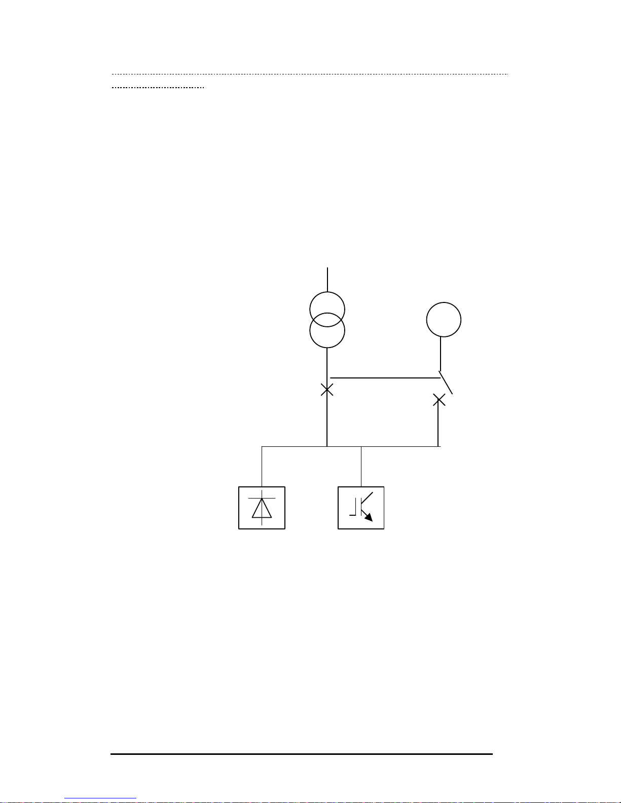
Many installations are fitted with back up generators to ensure the proper
operation of the installation in case of mains power outage.
A typical configuration is given here below.
Figure 6.9. Back-up generator: typical single-line diagram
The CT connection must be such that the active filter works whatever the type
of supply: generators or transformer-MV network.
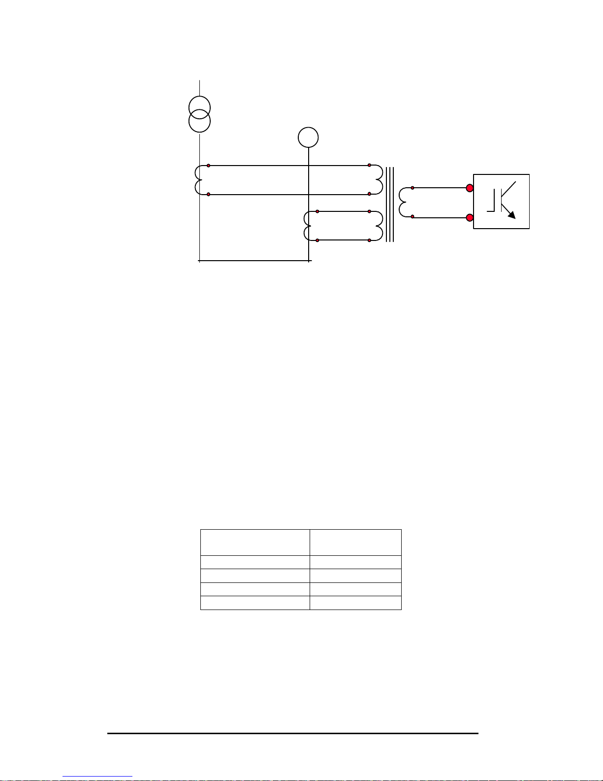
For each phase, one CT is installed in the transformer feeding and one in the
generator. Those two CT’s must be identical (X / 5 A) and are connected to a
summation CT rated 5+5 / 5 A.
The CT ratio to be programmed in the filter is: 2X/5.
G
LOAD
PQF
Page 43
PQFA Instructions Manual
Asea Brown Boveri Jumet S.A.
43
Figure 6.10. Back-up generator: CT connection (for one phase)
6.5. Precautions with capacitors
In the presence of power capacitors (LV or MV), harmonics below the
resonance frequency of the capacitor bank should not be handled by the filter
to avoid any risk of resonance. Those harmonics have to be deselected (see
chapter 10 on programming the filter).
Networks where the PQFA is installed have large harmonic content and it is
highly recommended that capacitor banks be fitted with detuning reactors.
The harmonics below the tuning frequency of the bank have also to be
deselected.
The following table indicates the harmonics to be deselected for main types of
detuned banks.
Detuned bank type Harmonics to
be deselected
5.67% 2, 3, 4.
6% 2, 3, 4.
7% 2, 3.
14% 2.
For other types of detuned bank or in the case of plain capacitors, please
contact your ABB Service provider to evaluate the resonance frequency and
the harmonics to be deselected.
S1, k
S2, l
S1, k
S2, l
P1
P2 P1 P2
S2
k
L
PQF
G
P1, K
P2, L
P1, K
P2, L
Page 44
PQFA Instructions Manual
Asea Brown Boveri Jumet S.A.
44
7. Cubicles interconnections
7.1. Introduction
This section explains how to connect PQF cubicles (Master-Slave or SlaveSlave) when they do not come connected from the factory or case or on-site
extension.
The section starts with mechanical installation.
Electrical connections are then described: interconnections between cubicles
and with the supply
All cables needed to make the connections are supplied with the units.
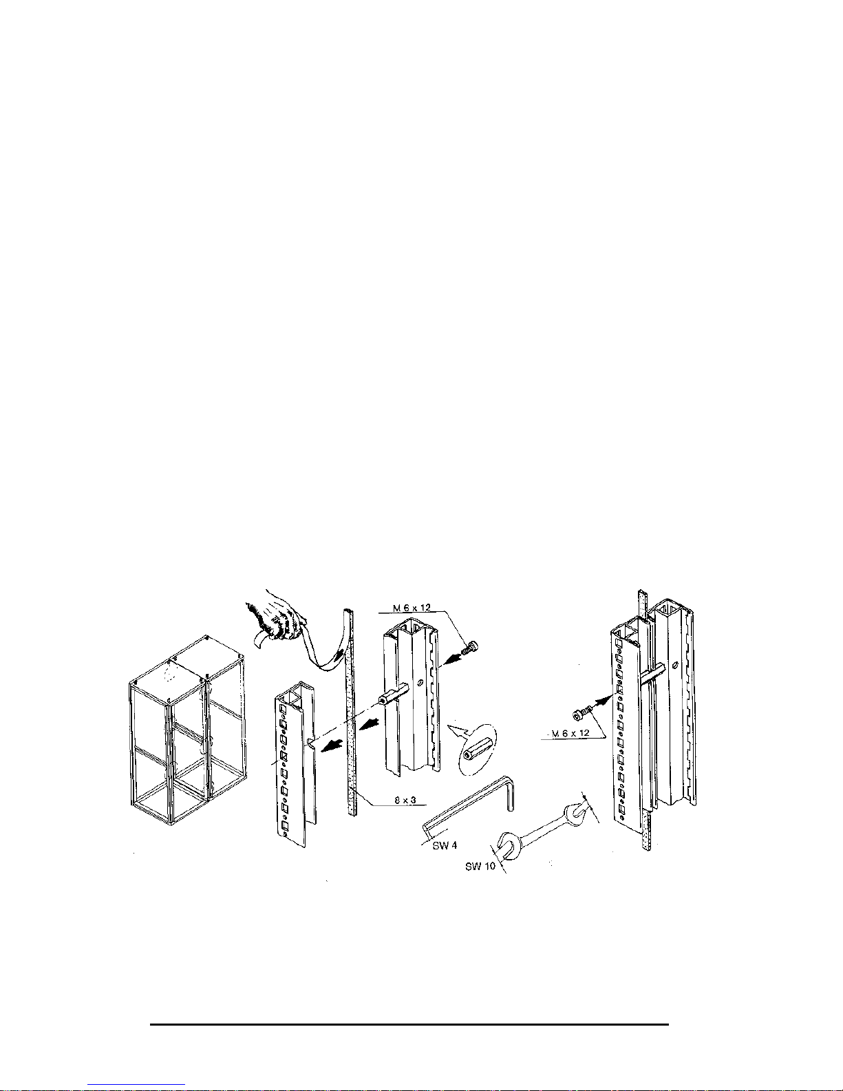
7.2. Mechanical installation
The side panels of the cubicles to be interconnected have first to be removed
(except the outside one of the Master and last Slave cubicles).
The provided divider panel seal has to be fixed on the interior frame between
cubicles.
Cubicles are then interconnected at 6 fixation points as indicated in Figure
3.1.
The baying kit is provided with the cubicles (not the tools).
Figure 7.1. Mechanical installation
Page 45
PQFA Instructions Manual
Asea Brown Boveri Jumet S.A.
45
7.3. Electrical connections
7.3.1. Connections between cubicles
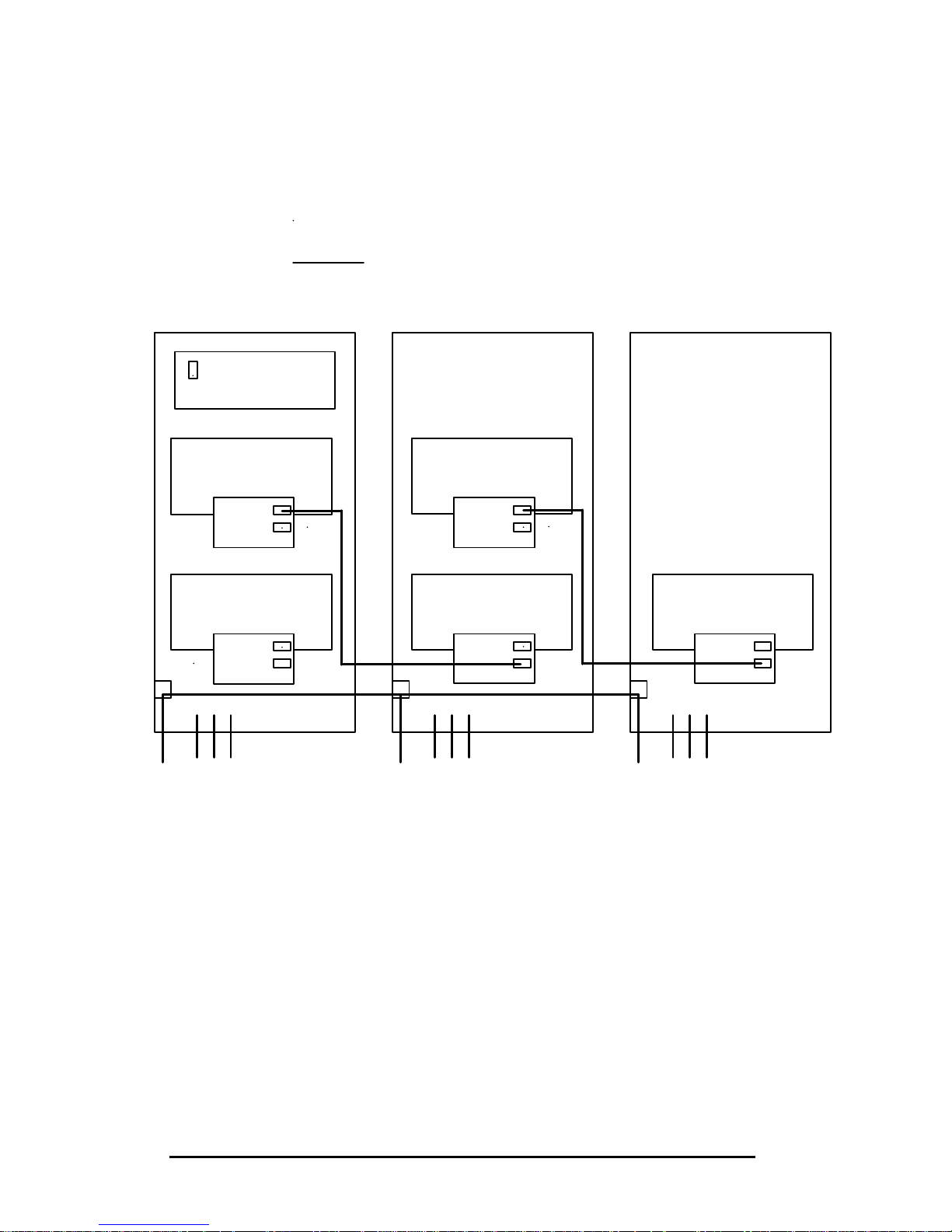
77..33..11..11.. PPoowweerr ccoonnnneeccttiioonn
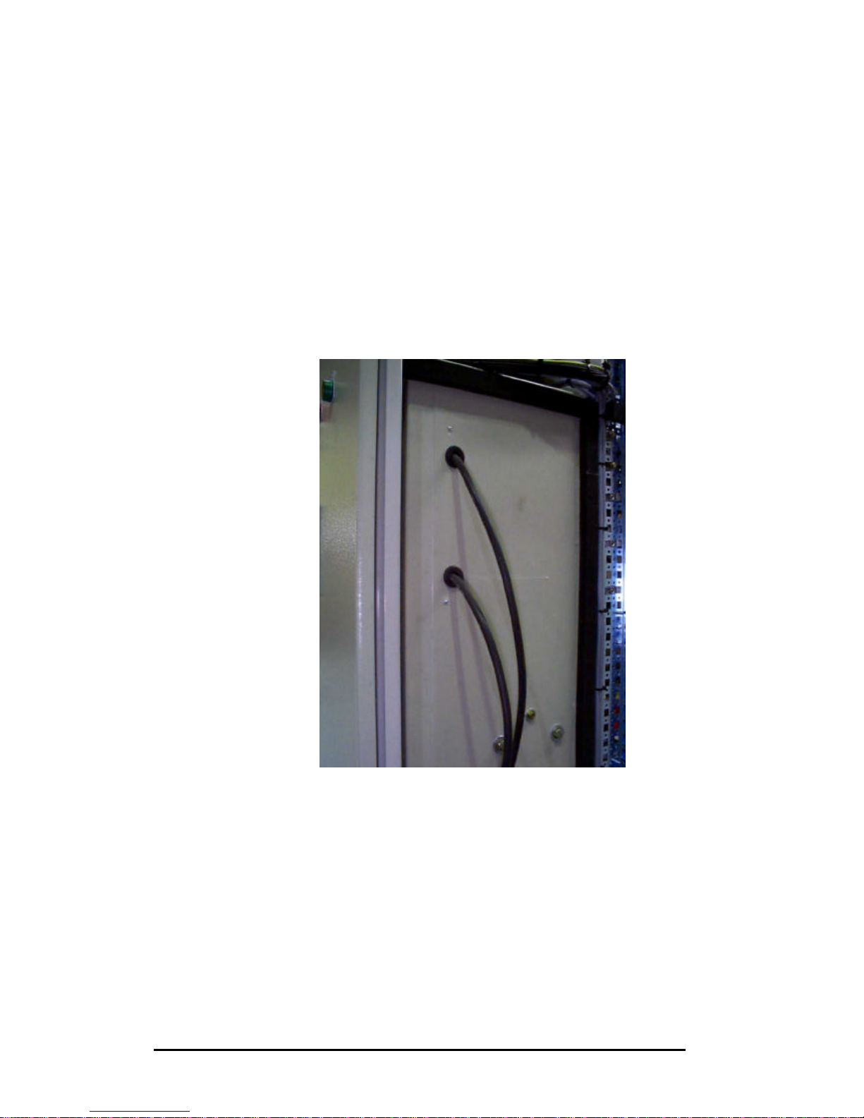
The DC bus of the master and slave cubicles must be connected.
Each slave cubicle comes from the factory with two cables connected on the +
and - poles of the DC bus.
Those cables must be entered in the power modules case of the next cubicle
through the corresponding holes as represented on Picture 7.1.
Picture 7.1. DC bus interconnection
The cables are then fixed to the terminals of the DC bus of the next cubicle.
Page 46
PQFA Instructions Manual
Asea Brown Boveri Jumet S.A.
46
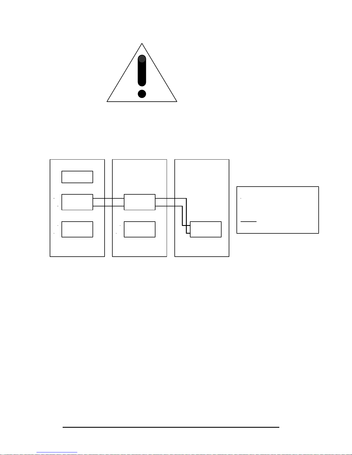
Start the DC buses interconnection with the last slave and proceed similarly
with each cubicle until reaching the Master.
An example of DC bus interconnection is given below (PQFA-B+D+C) in
Figure 7.2.
Figure 7.2. DC bus interconnection
77..33..11..22.. CCoonnttrrooll ccoonnnneeccttiioonn
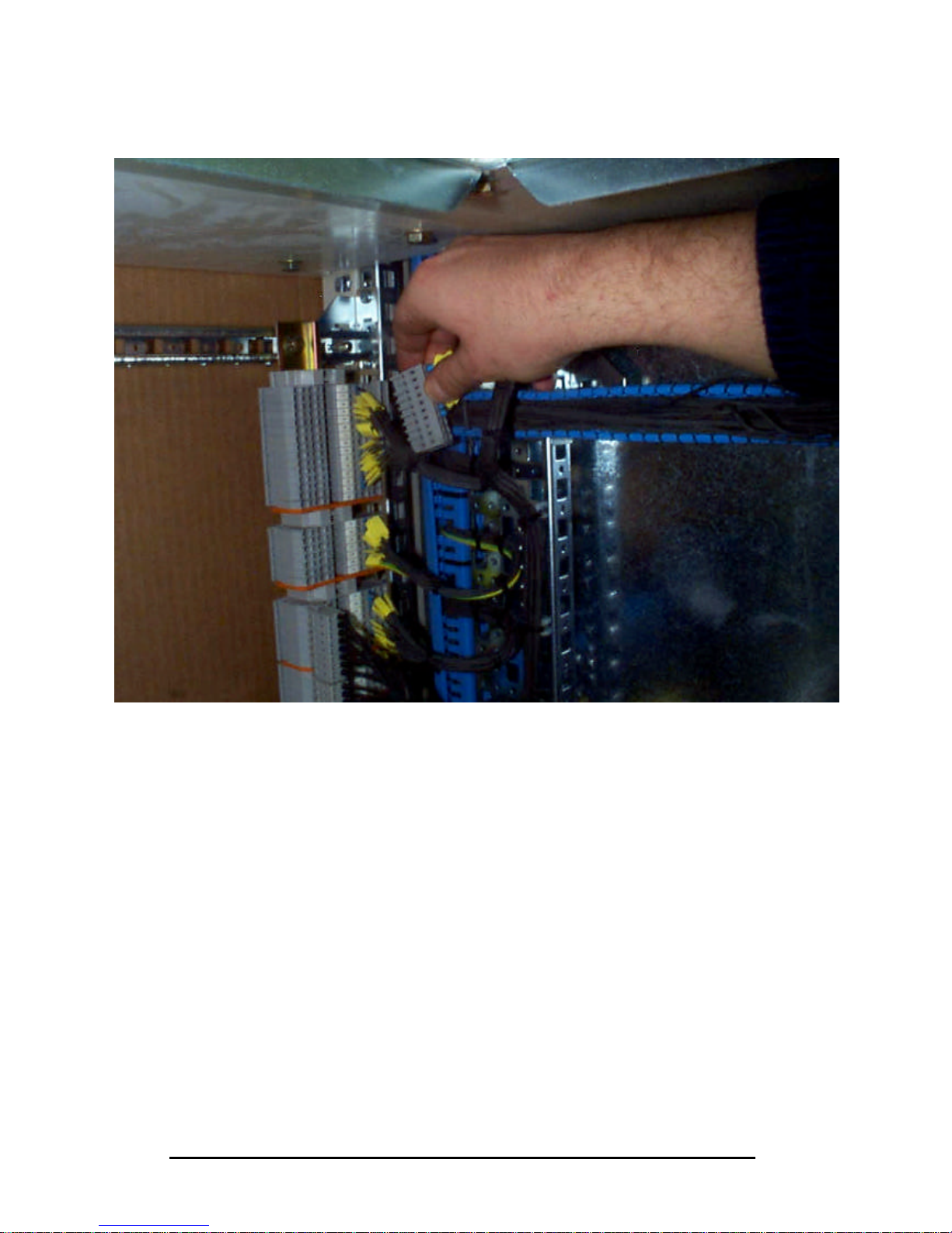
Each slave cubicle comes from the factory with a bunch of 7 cables
connected to terminal X13.
Those cables fed a common Wago connector that has to be connected to
terminal X13 of the next cubicle, starting connection with the bunch of the last
slave (Picture 7.2)
Be very careful about the polarity
when connecting the DC bus.
Module 2
Module 1
Module 4
Module 3 Module 5
Control
+
-
+
-
+
-
-
+
+
+
+
-
Internal
External
connection to
Page 47
PQFA Instructions Manual
Asea Brown Boveri Jumet S.A.
47
Picture 7.2. Control connection
Make sure that the plug-in pattern of the connector and plug is respected. The
correspondence between X13 terminals will then be fulfilled as indicated on
the electrical wiring diagram.
The last cubicle of the chain must contain a bridge between X13.1 and X13.2.
77..33..11..33.. DDoommiinnoo bbooaarrddss ccoonnnneeccttiioonn
The inter-domino boards connection is achieved with flat cables.
Each slave cubicle is fitted with a loose flat cable. The other end of this flat
cable has to be connected to the first plug of domino board A118 of the next
cubicle, starting at the last slave.
Make sure that the plug-in pattern of the connector and plug is respected.
Page 48

PQFA Instructions Manual
Asea Brown Boveri Jumet S.A.
48
The last domino of the chain must be fitted with termination jumpers on
positions JP100, JP101, JP102, JP103, JP104, JP105, JP106, JP109 and
JP110 (JP107 and JP108 are off).
An example of domino boards interconnection is given in Figure 7.3 (PQFAB+D+C).
77..33..11..44.. EEaarrtthh ccoonnnneeccttiioonn
The earth cable of each slave cubicle has to be connected to the earth
connection point of the master cubicle. Make sure that the cables run along
the floor, not over components.
7.3.2. Connections to the supply
77..33..22..11.. PPoowweerr ccoonnnneeccttiioonn
Three power cables (L1, L2, L3) have to be connected to each circuit breaker
(one in each cubicle).
Make sure that L1, L2 and L3 in each cubicle are connected to the same
phases.
77..33..22..22.. PPrrootteeccttiivvee eeaarrtthh
The protective earth point of each cubicle has to be connected to earth.
The connections to the supply are represented in Figure 7.3.
Page 49
PQFA Instructions Manual
Asea Brown Boveri Jumet S.A.
49
Figure 7.3. Flat cables connection and connections to power supply
Control
Module 2
Domino
Module 1
Domino
Module 5
Domino
Module 3
Domino
Module 4
Domino
L1 L2 L3
PE
L1 L2 L3 L1 L2 L3
PE
PE
Internal connection
External connection to perform
Page 50
PQFA Instructions Manual
Asea Brown Boveri Jumet S.A.
50
8. PQF-Prog installation and PC connection
The PQF-Prog, included in the standard PQFA package, allows for the
complete programming of the filter. It consists of two Micro Floppy Disks
delivered with the filter.
8.1. System requirements
Windows NT 4.0 Service Pack 3 minimum.
At least one free COM:port (RS232 - DB 9).
One standard RS232 cable (male-female non twisted)
8.2. Installing PQF-Prog on your PC
1. Insert disk 1 of PQF-Prog in drive A
2. In the Start Menu, choose Run
3. In the Command Line box enter
a:\setup
4. Follow the instructions in the dialog boxes to:
?? Specify the drive and directory (c:\ Program Files \ Pqf is the
default)
?? Complete the installation
8.3. Hardware connection
A111 A112 A113 A119 A114 A115 A116 U100 U109
DIG
INT
DSP GUI LIC
LVI
ALIM/GND
±15V +5V
YELLOW LED
GREEN LED
RED LED
1 2
3
21
3
21 21 21 1
21 1 2
3 4 3
RS232
-
port
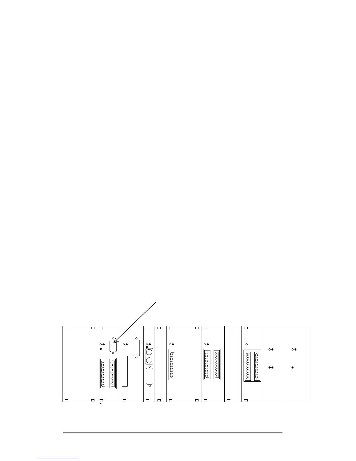
If your filter is equipped with the PQF
-
Manager
, you just have to plug the DB
9 connection in the RS232 port situated at the front of the PQF-Manager.
If your filter is not equipped with the PQF-Manager
, you have to plug the
connection in t
he RS232 port located on the control rack (A111: digital I/O
board) as shown here after.
Page 51
PQFA Instructions Manual
Asea Brown Boveri Jumet S.A.
51
9. Commissioning
The commissioning of your PQFA should be conducted in strict accordance
with the following procedure.
Warning: Before applying the commissioning procedure, make sure that
you become familiar with programming instructions (see chapter 10,
programming with PQF-Prog and PQF-Manager).
Pay particular attention to the presence of capacitors on the network.
The commissioning procedure consists in 8 steps that should be followed very
carefully.
Step 1 Installation check
Step 2 Voltage phase rotation
Step 3 Current transformer check
Step 4 System set-up
Step 5 Before starting the filter
Step 6 Start the filter
Step 7 Stop the filter
Step 8 Start filtering
9.1. Step 1
Step 1: Visual and installation check
Check first that mechanical and electrical installations fulfil requirements
described in chapter 4 and 5 of the present manual.
Check also visually the conditions of the filter and the tightness of
connections. In particular, verify that all connections on the control rack,
domino board and IGBT are properly plugged in.
9.2. Step 2
Step 2: Voltage phase rotation
Voltage phase rotation must be clockwise (L1 -> L2 -> L3 -> L1). Wrong
phase rotation may damage the filter.
Page 52
PQFA Instructions Manual
Asea Brown Boveri Jumet S.A.
52
9.3. Step 3
Step 3: Current transformer check
Improper CT connection is the most frequent cause of problems during
commissioning.
The following procedure will allow you to check the CT connection.
Warning: The secondary circuit of a loaded CT must never be opened
otherwise extremely high voltages may appear which can
lead to physical danger or destruction of the CT itself.
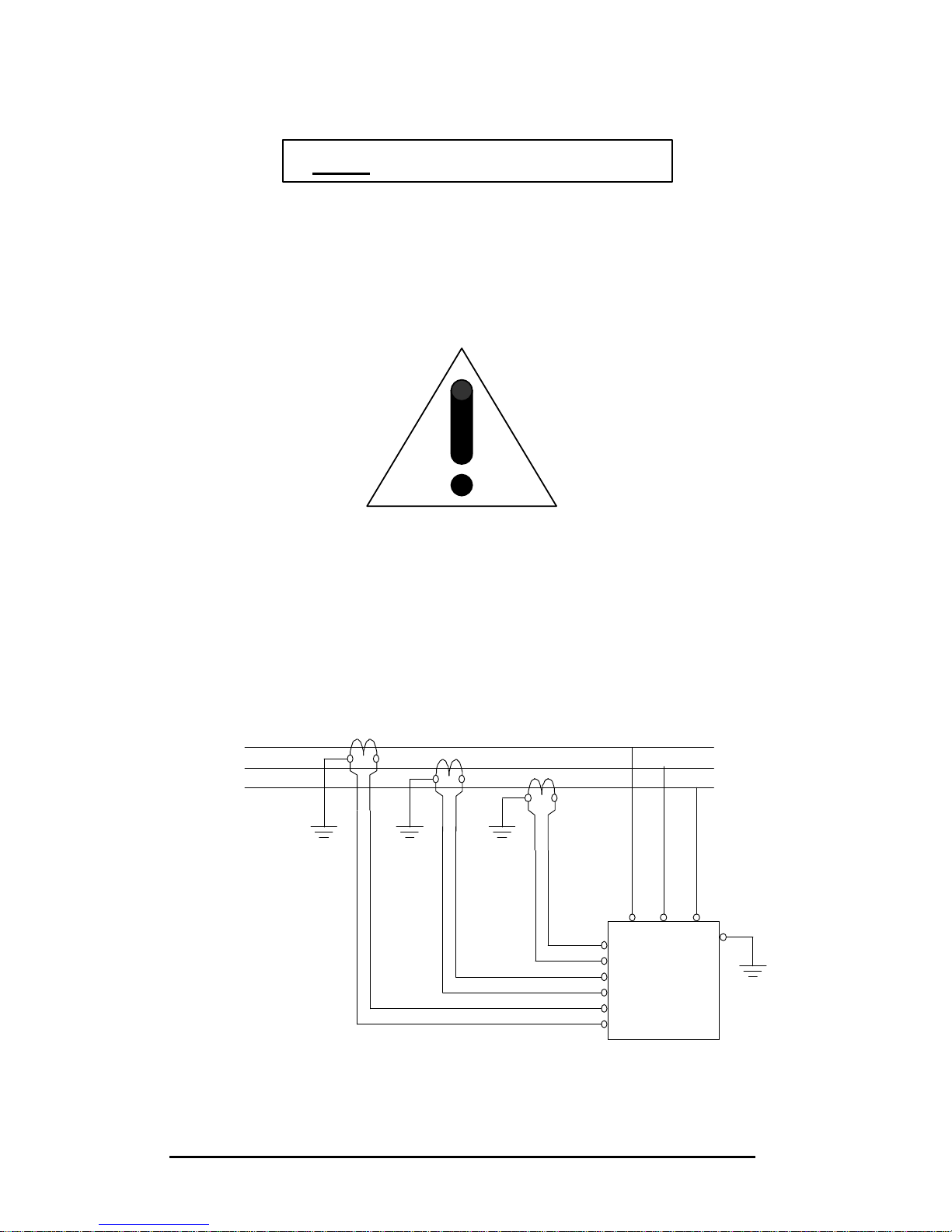
9.3.1. PQF connection diagram
Figure 9.1. shows the normal connection of the PQF. It must be noted that:
?? L1, L2 and L3 rotation must be clockwise,
?? The CTs must be on the supply (line) side of the PQF,
?? One secondary terminal of the CT must be earthed.
L1
L2
L3
Load sideSupply side
K L
k l
K L
k l
K L
k l
PQF
X5.2
X5.3
X5.4
X5.5
X5.6
X5.1
L1 L2 L3
Figure 9.1. PQF connection
Page 53
PQFA Instructions Manual
Asea Brown Boveri Jumet S.A.
53
It is also seen that terminal X5.1 and X5.2 are related to the CT located in
phase L1, terminal X5.3 and X5.4 are related to the CT located in phase L2
and terminal X5.5 and X5.6 are related to the CT located in phase L3.
9.3.2. Material needed & hypotheses for correct measurements
A two channel scopemeter with one voltage input and one current input is
needed. Adequate sensors are also needed. A power analyser like the Fluke
41B can also be used.
Some minor knowledge of the load is also required. For instance, the method
explained below is based on the fact that the load is inductive and not
regenerative (i.e. the load current lags by less than 90° the phase voltage). If
a capacitor bank is present, it is better to disconnect it before making
measurements in order to ensure an inductive behaviour of the load. It is also
assumed that the load is approximately balanced.
9.3.3. Checking the correct connection of the CTs with a two channel
scopemeter.
The first channel of the scopemeter must be connected to the phase voltage
referenced to the neutral or to the ground if the neutral is not accessible.
The second channel must measure the associated current flowing from the
network to the load as seen by the CT input of the PQF.
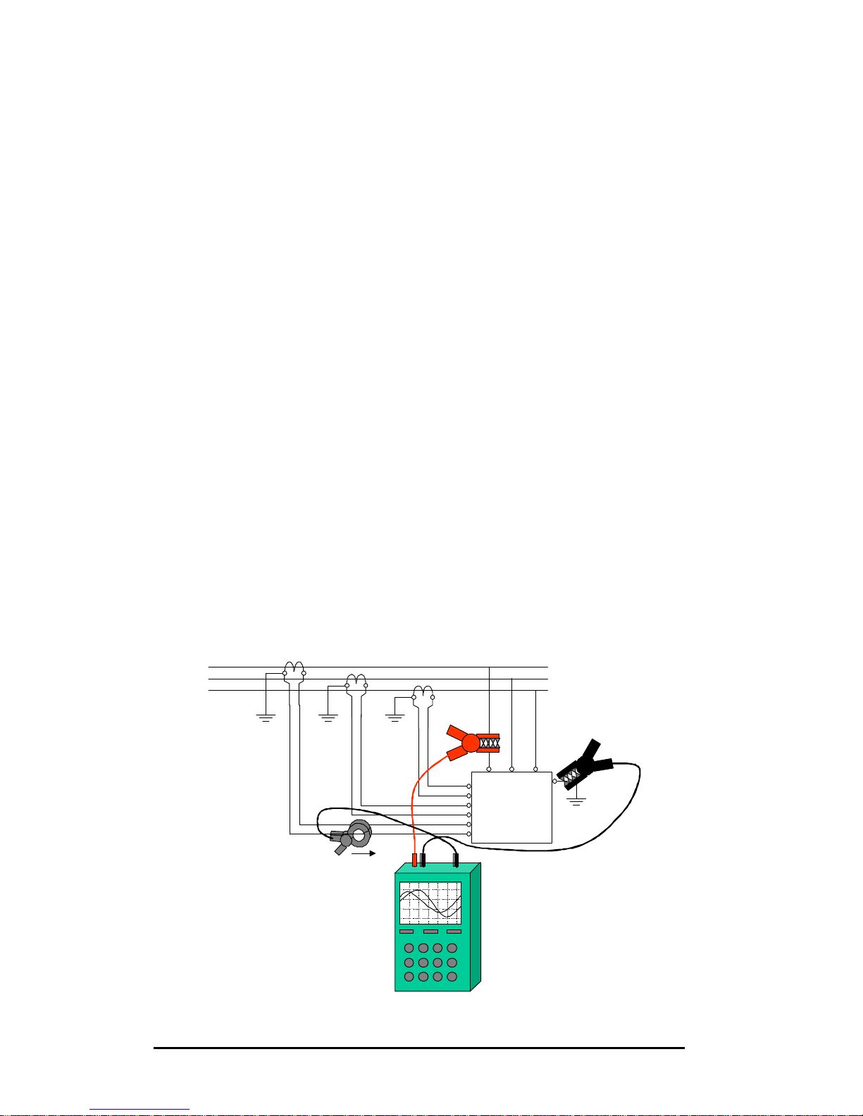
99..33..33..11.. MMeeaassuurreemmeenntt ooff CCTT iinn pphhaassee LL11
For the voltage measurement (channel 1), the positive (red) clamp must be
connected to the phase L1 and the negative clamp (black) must be connected
to the neutral (ground).
For the current measurement (channel 2), the clamp should be inserted into
the wire connected on terminal X5.1 and the arrow indicating positive direction
of the current should point towards the PQF. Do not forget to remove the short
on the CT secondary before making the measurement.
L1
L2
L3
Load sideSupply side
K L
k l
K L
k l
K L
k l
PQF
X5.2
X5.3
X5.4
X5.5
X5.6
X5.1
L1 L2 L3
Positive direction
Ch1 Ch2
Figure 9.2. Connection of the scopemeter for checking CT in phase L1.
Page 54
PQFA Instructions Manual
Asea Brown Boveri Jumet S.A.
54
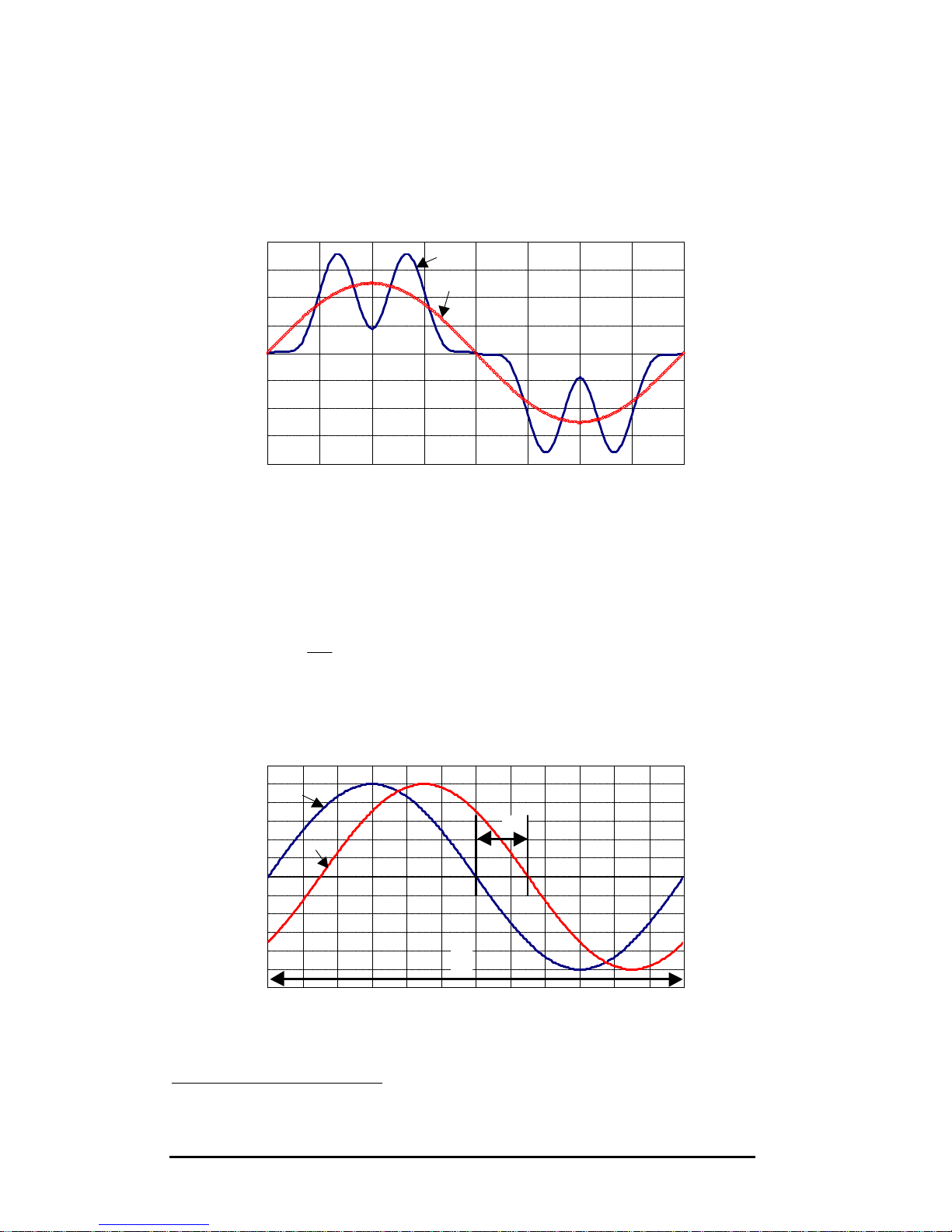
On the scopemeter screen, two waveforms should appear. The voltage
waveform should be approximately a sine wave1 and the current waveform
would normally be a well distorted wave because of harmonic distortion.
Usually, it is quite easy to extrapolate the fundamental component as it is the
most important one (Figure 9.3).
I
I1
Figure 9.3. Extrapolation of fundmental component from a distorted
waveform.
From the fundamental component of both signals, the phase shift must then
be evaluated (Figure 9.4). The time ?T between zero crossing of the rising
(falling) edge of both traces must be measured and converted to a phase shift
? by the following formula:
?
?
? 360*
1
T
T
?
where T1 is the fundamental period duration.
For an inductive and non regenerative load, the current signal should lag the
voltage by a phase shift lower than 90°.
?T
T
1
U
I1
Figure 9.4. Phase shift evaluation between two waveforms.
1
If the earthing of the system is bad, the phase to ground voltage may appear like a very distorted waveform. In this
case, it is better to measure the phase to phase voltage (move the black clamp to the phase L2) and substract 30° on
the measured phase shift.
Page 55
PQFA Instructions Manual
Asea Brown Boveri Jumet S.A.
55
99..33..33..22.. MMeeaassuurreemmeenntt ooff CCTT iinn pphhaassee LL22 aanndd LL33
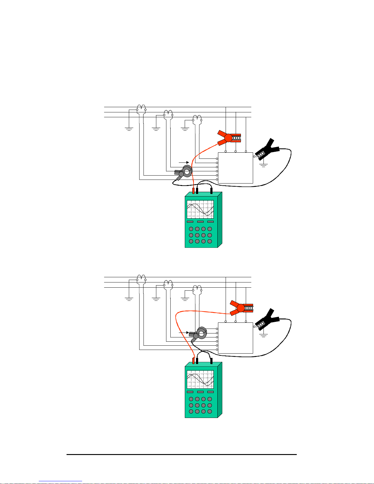
The same operations as those described in the previous paragraph must be
repeated with the phase L2 (Figure 9.5) and phase L3 (Figure 9.6).
For a balanced load (which is usually the case in most of the three phase
systems), the phase shift should be approximately the same for all the three
phases.
L1
L2
L3
Load sideSupply side
K L
k l
K L
k l
K L
k l
PQF
X5.2
X5.3
X5.4
X5.5
X5.6
X5.1
L1 L2 L3
Positive direction
Ch1 Ch2
Figure 9.5. Connection of the scopemeter for checking CT in phase L2.
L1
L2
L3
Load sideSupply side
K L
k l
K L
k l
K L
k l
PQF
X5.2
X5.3
X5.4
X5.5
X5.6
X5.1
L1 L2 L3
Positive direction
Ch1 Ch2
Figure 9.6. Connection of the scopemeter for checking CT in phase L3.
Page 56
PQFA Instructions Manual
Asea Brown Boveri Jumet S.A.
56
9.3.4. Checking the correct connection of the CTs with two current probes.
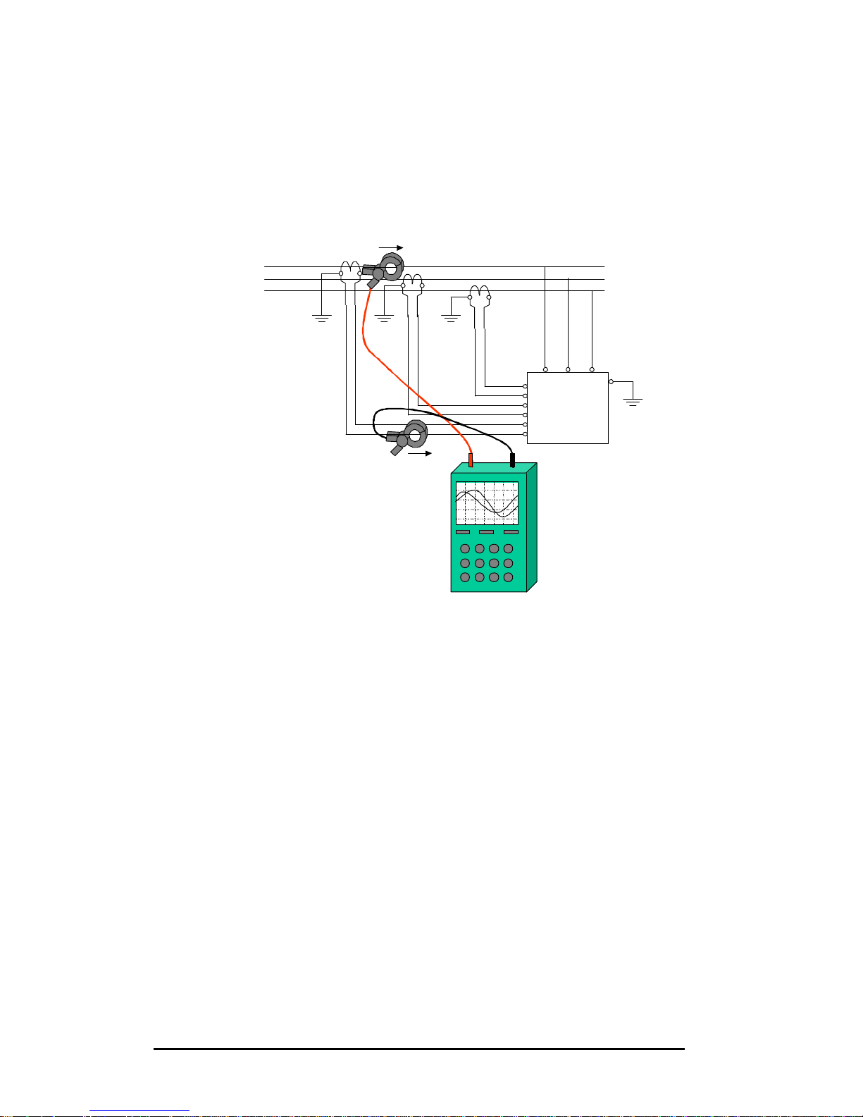
If the main bus bar is available and all security rules are taken, it is possible to
use the two channel scope meter in order to see if the current measured
through the CT is matching the real current in the bus. Connecting the current
probes as shown on Figure 9.7., the two traces must be in phase and of the
same shape (the magnitude could be different as the gain are different) if the
wiring is correct.
L1
L2
L3
Load sideSupply side
K L
k l
K L
k l
K L
k l
PQF
X5.2
X5.3
X5.4
X5.5
X5.6
X5.1
L1 L2 L3
Ch1 Ch2
Positive direction
Positive direction
Figure 9.7. Connection of the scopemeter for checking CT in phase L1
by comparing the currents.
This operation has to be repeated for the remaining two phases for a
complete check. The current probes have to be changed accordingly.
9.3.5. Checking the correct connection of the CTs with a Fluke 41B.
The Fluke 41B is a power analyser that allows measurements of one voltage
and one current wave. Unfortunately, the device does not allow simultaneous
display of both waveforms on the screen. But it is possible to synchronise the
triggering on either the voltage or on the current. All phaseshift measurements
are then referenced to the chosen origin. To read directly the phaseshift
between the fundamental components, just select the spectrum window of the
signal which is not chosen as the origin.
The instrument must be configured in single phase measurements.
The probes must be connected as shown on Figure 9.2, Figure 9.5 and Figure
9.6.
Page 57
PQFA Instructions Manual
Asea Brown Boveri Jumet S.A.
57
9.4. Step 4
Step 4: System set-up
9.4.1. With PQF-Prog
Once the PQF-Prog software has been successfully installed and your PC is
properly connected (see chapter 8), select Programs in the Start menu and
click on PQF. If you did not install PQF-Prog in the Program Files directory,
create a shortcut to PQF_Prog.exe.
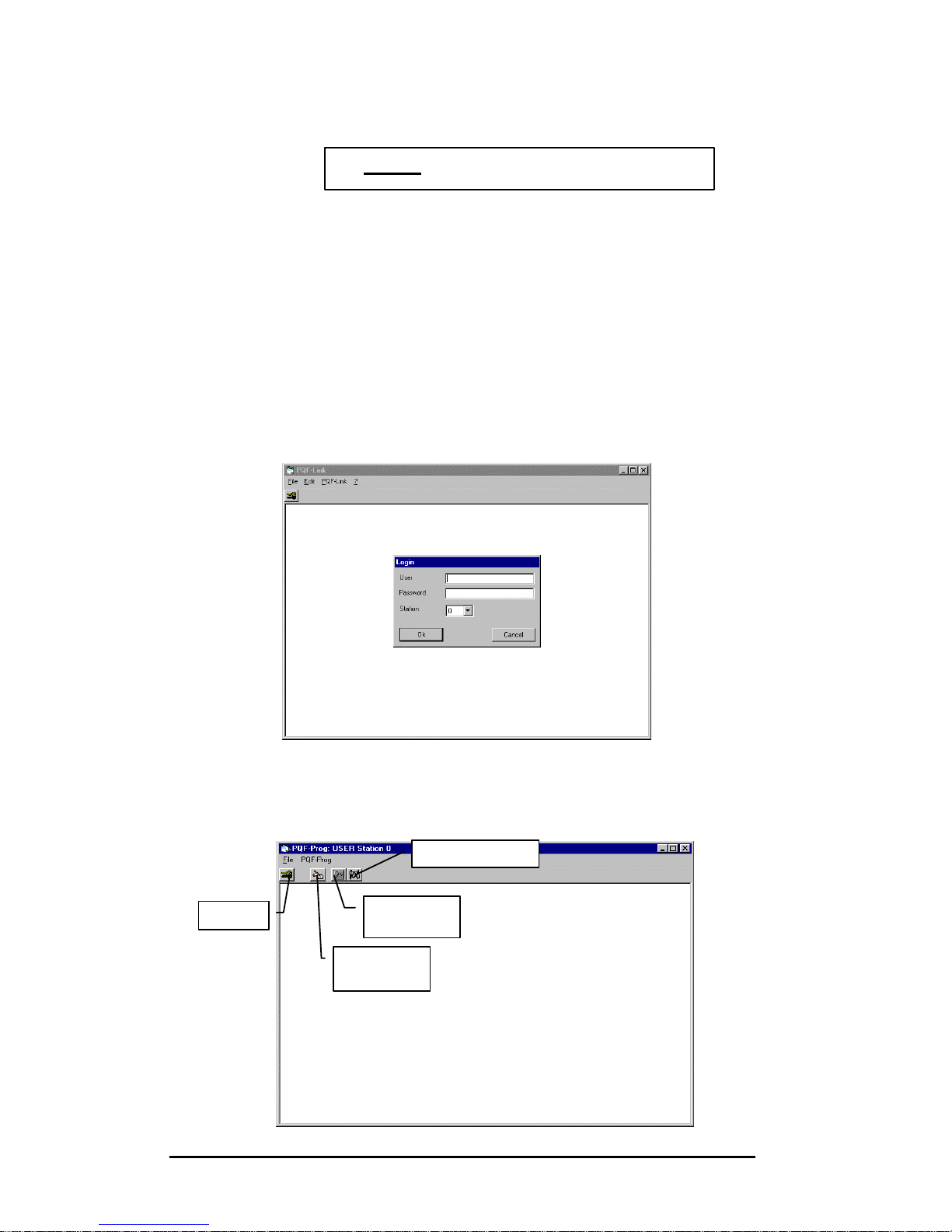
After launching PQF-Prog, a text box indicating that Station 0 has been found
will appear. Click ‘Done’. You then enter the PQF-Prog main Window.
In the Login box, type the User name and the password. Station must be “0”.
If you use the appropriate User name and password, four icons appear on the
toolbar: Login, Filter Operation, Hardware set-up and Configuration.
Login
Filter
Operation
Hardware
set-up
Co
nfiguration
Page 58

PQFA Instructions Manual
Asea Brown Boveri Jumet S.A.
58
If a wrong or no login is entered, you will only have access to the Login, Filter
Operation and Configuration icons.
Click on the Hardware set-up icon.
In the hardware set-up window, you will have to specify:
?? The network frequency
?? The grid nominal voltage
?? The number of modules
?? The three lines CT ratio
Click on ‘apply’ to validate.
9.4.2. With the PQF-Manager
The 3 levels of the PQF-Manager are accessible from the window “Main
menu”.
To enter the “Main menu” window, press MENU.
Level 1 is for consulting, level 2 for filter programming and level 3 for
commissioning.
Select level 3 by pressing once the ? key.
Then press OK and enter the appropriate password for level 3.
The LED ‘SET’ will switch on.
In the hardware set-up window, you will have to specify:
?? The network frequency
?? The grid nominal voltage
?? The number of modules
?? The three lines CT ratio
MAIN MENU
Level 1
Level 2
? Level 3?
Page 59
PQFA Instructions Manual
Asea Brown Boveri Jumet S.A.
59
9.5. Step 5
Step 5: Before switching the filter on
Before switching the filter ON, you have to ensure that all harmonics and
reactive power compensation have been deselected. This can be done from
the ‘Filter Operation’ menu of the PQF-Prog or level 2 of the PQF-Manager.
Please refer to the detailed programming instructions of chapter 10.
9.6. Step 6
Step 6: Starting the filter
With all harmonics and reactive power compensation deselected, you can
start the filter by pushing the RUN button of the master cubicle.
The main breaker should close within 30 seconds. One second after closing,
the IGBT will start and the filter will work under no load condition.
9.7. Step 7
Step 7: Stop the filter
Once the filter is connected to the network, stop it by pushing on the RESET
button.
9.8. Step 8
Step 8: Start filtering
Once you have checked that the filter can connect to the network, you may
start filtering and reactive power compensation.
After programming the filter according to the procedure of chapter 10, you can
switch the filter on by pushing the RUN button.
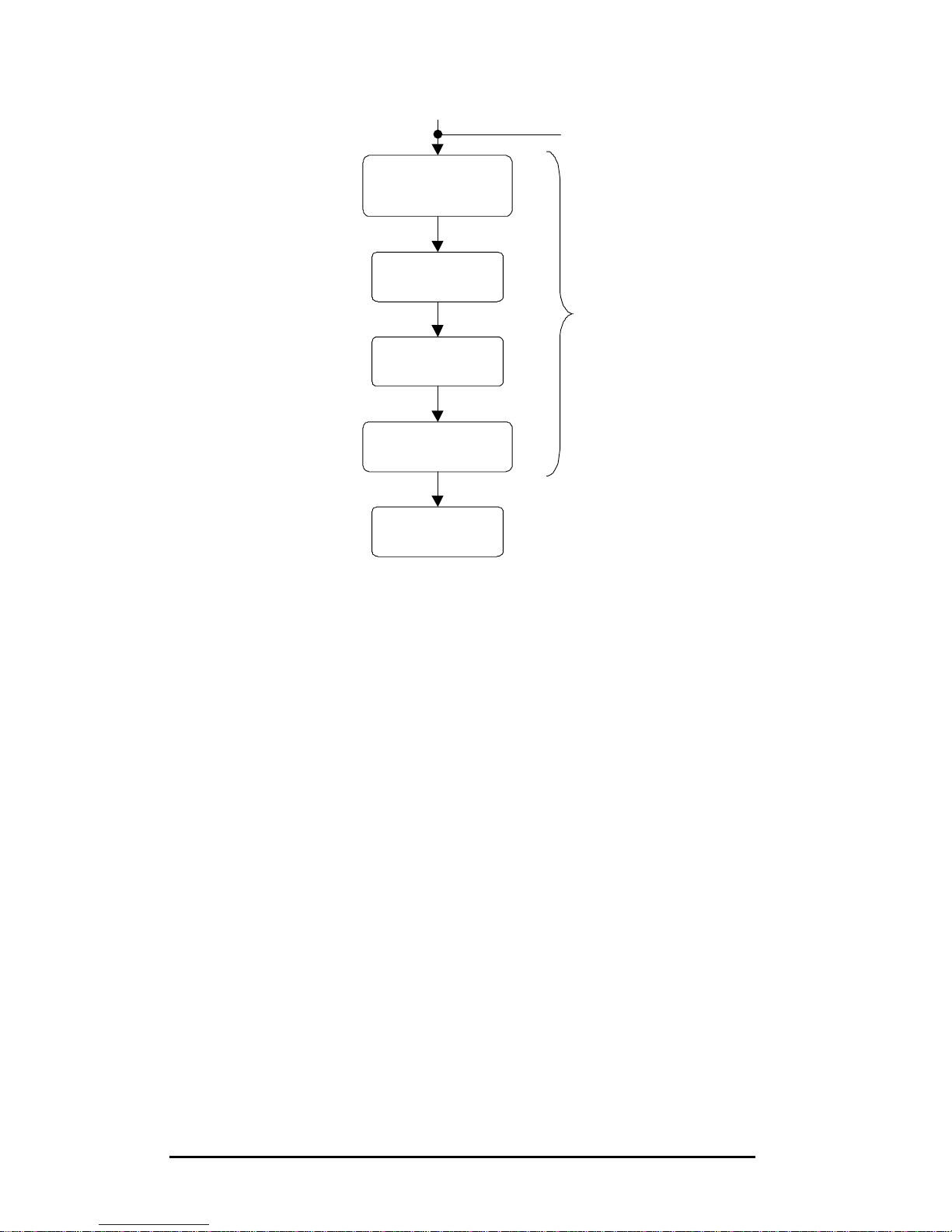
A start-up sequence will then be conducted.
As represented on Figure 9.8, this sequence includes a network
characterisation during which the filter may generated ‘musical’ sounds.
Page 60
PQFA Instructions Manual
Asea Brown Boveri Jumet S.A.
60
Figure 9.8. Start-up sequence
Start fan &
preload
DC bus
Operation as
programmed
Close MC
Start IGBT
Network
characterisation
Push RUN button
Start-up sequence
Page 61
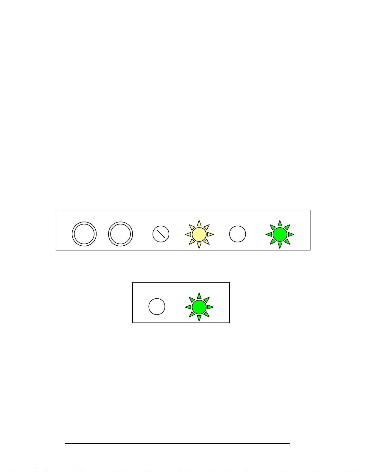
PQFA Instructions Manual
Asea Brown Boveri Jumet S.A.
61
10. Operation
10.1. Normal working sequence
After successful commissioning (refer to chapter 9), the procedure to operate
the active filter is:
1. From the OFF position (auxiliary and main breaker open, no light on),
switch on the auxiliary breaker.
If your PQFA system has more than two modules, the auxiliary breaker of
slave cubicles should be switched on before the one of the master cubicle.
2. After 20 seconds, the system will reset.
3. The auxiliaries are then on but the main circuit breaker is still open.
The white light (ON) and the green one (OPEN) of the master cubicle are on,
while the green light (OPEN) of the slave cubicles is on.
Master cubicle lights and buttons:
Slave cubicles lights:
If your PQFA is fitted with the PQF-Manager, the red LED ‘POWER’ is on.
CLOSE
OPEN
RESET
RUN LOC/REM
ON CLOSE
OPEN
Page 62
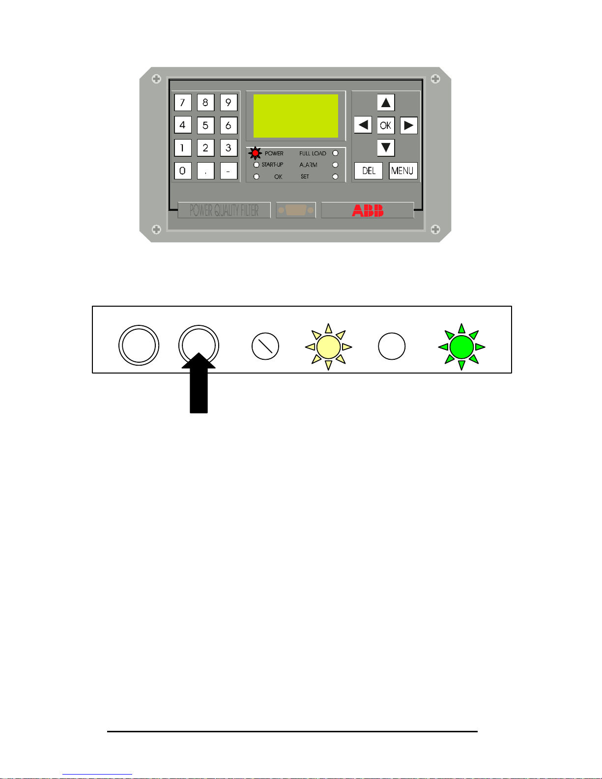
PQFA Instructions Manual
Asea Brown Boveri Jumet S.A.
62
4. Push the RUN button located on the master cubicle.
5. The filter then starts the start-up sequence:
- Start fan and preload DC bus
- Close main circuit breaker
- Start IGBT
- Network characterization
During the start-up sequence, the red LED ‘START-UP’ of the PQF-Manager
is on.
RESET
RUN LOC/REM
ON CLOSE
OPEN
Page 63
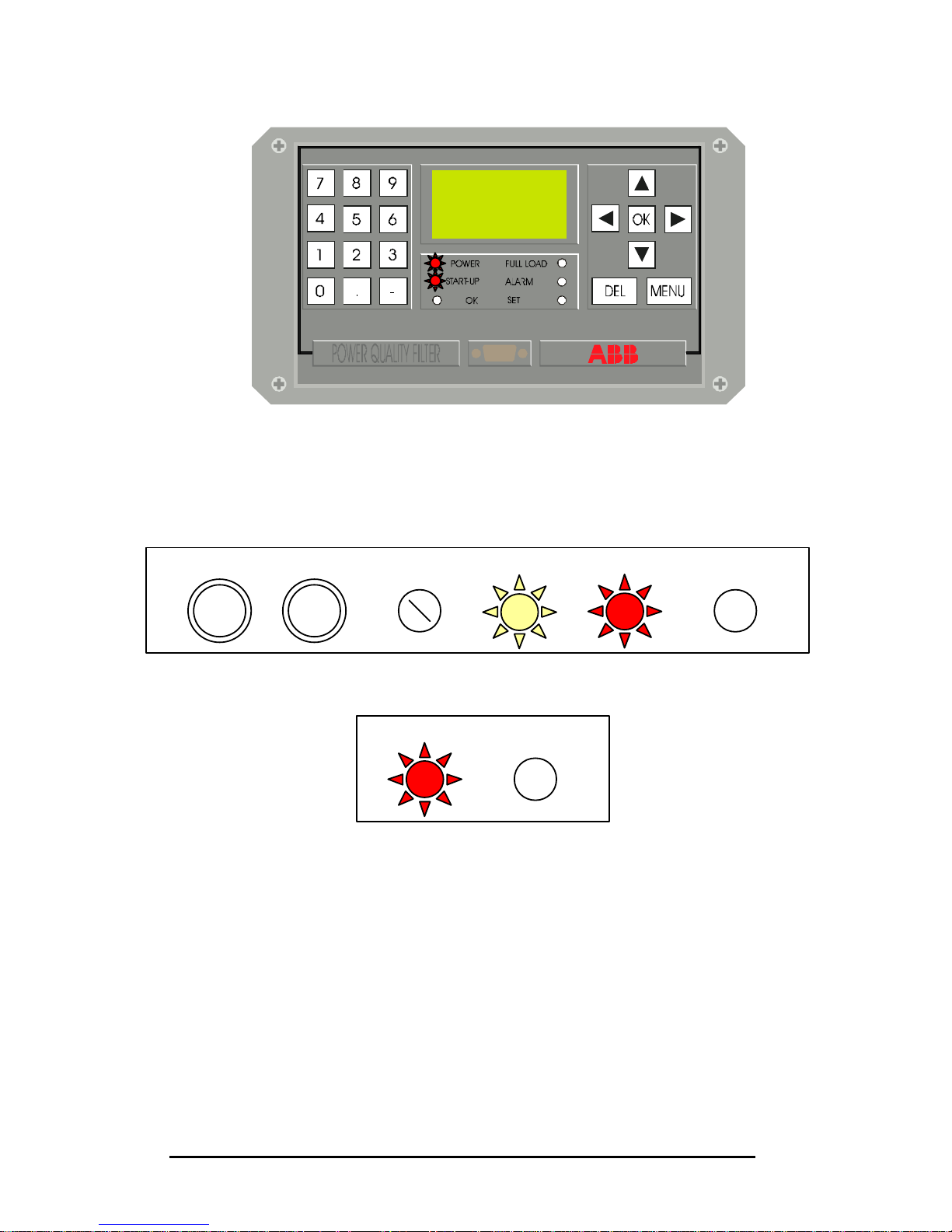
PQFA Instructions Manual
Asea Brown Boveri Jumet S.A.
63
Once the main circuit breaker is closed, the red light (CLOSED) of the master
and slave cubicles becomes on, while the green light (OPEN) switches off.
Master cubicle
Slave cubicles:
LED n°3 of board A111 on the control rack should be red: it indicates that the
PQF is properly synchronized to the network (see illustration next page).
6. After the start-up sequence, the PQFA operates as programmed. The red
LED ‘OK’ of the PQF-Manager should be on.
In the LED ‘FULL LOAD’ appears to be on, it only means that the filter cannot
achieved the programmed requirements. Refer to the chapter on
programming with the PQF-Manager for more information.
CLOSE
OPEN
RESET
RUN LOC/REM
ON CLOSE
OPEN
Page 64
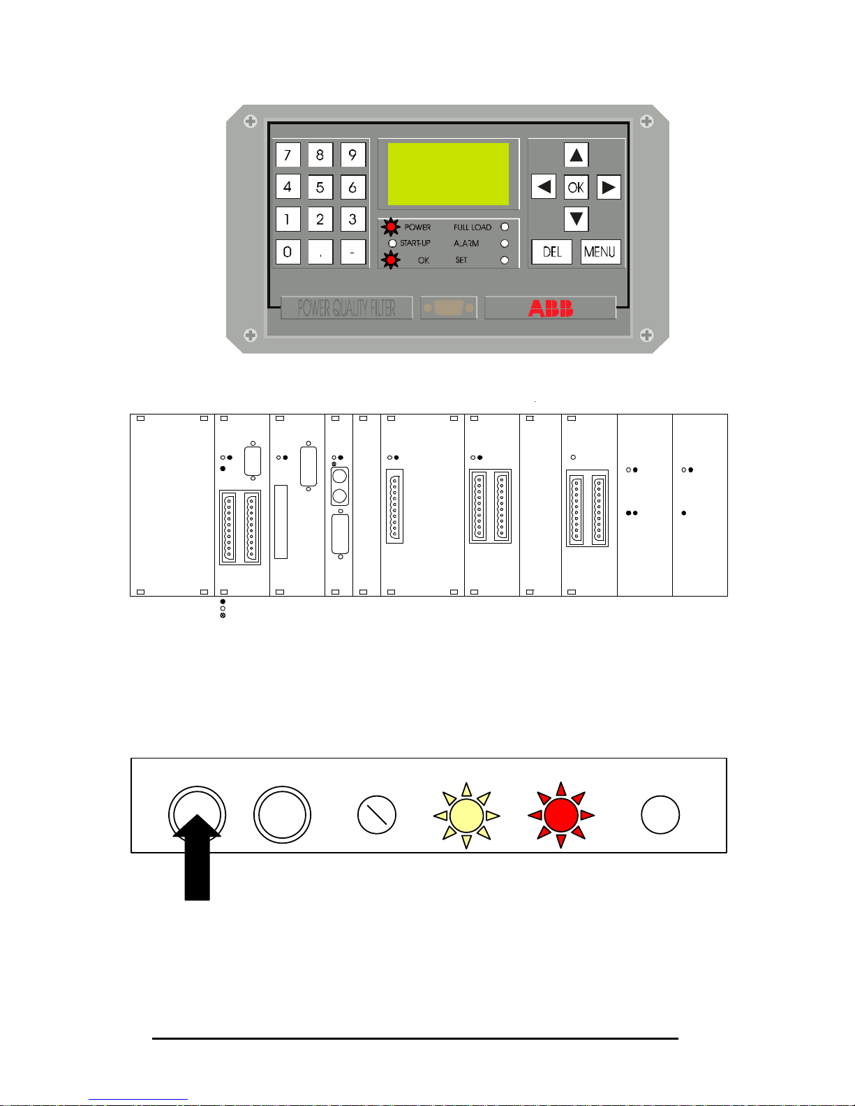
PQFA Instructions Manual
Asea Brown Boveri Jumet S.A.
64
7. Pushing the button RESET of the master cubicle causes the main
circuit breaker to open and to come back at step 3 of this procedure.
The normal working sequence is represented on Figure 10.1.
A111 A112 A113 A119 A114 A115 A116 U100 U109
DIG
INT
DSP GUI LIC
LVI
ALIM/GND
±15V +5V
YELLOW LED
GREEN LED
RED LED
1 2
3
21
3
21 21 21 1
21 1 2
3 4 3
RESET
RUN LOC/REM
ON CLOSE
OPEN
Page 65
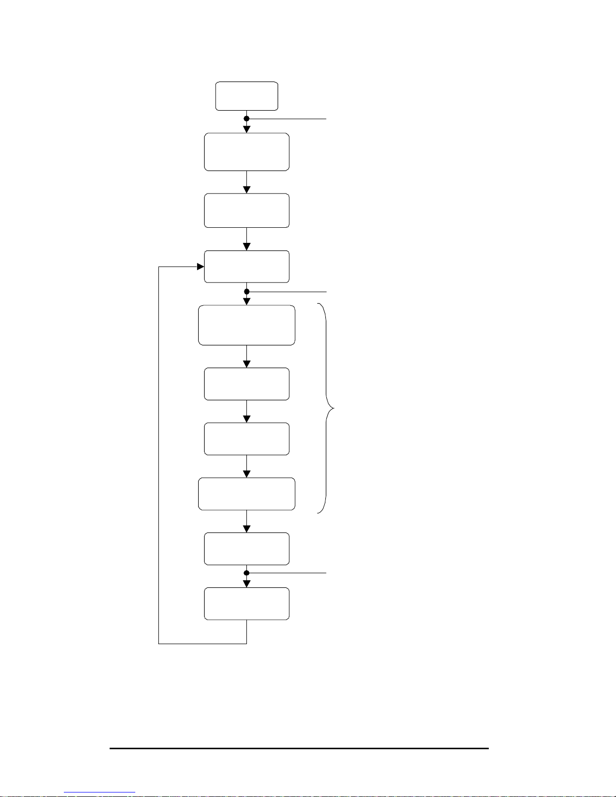
PQFA Instructions Manual
Asea Brown Boveri Jumet S.A.
65
Figure 10.1. Normal working sequence
OFF
20sec.
Time delay
System reset
Auxiliaries ON
Start fan &
preload
DC bus
Operation as
programmed
Open MC
Close MC
Start IGBT
Network
characterisation
Switch on auxiliary breaker (Q101)
Push RUN button
Push RESET button
Start-up sequence
Page 66

PQFA Instructions Manual
Asea Brown Boveri Jumet S.A.
66
10.2. Operation with capacitors
Networks where the PQFA is installed have large harmonic content and it is
highly recommended that capacitor banks, if present, be fitted with detuning
reactors. In that case, harmonics orders below the tuning frequency of the
bank should not be handled by the filter.
The following table indicates the harmonics to be deselected for main types of
detuned banks.
Detuned bank type Harmonics to
be deselected
5.67% 2, 3, 4.
6% 2, 3, 4.
7% 2, 3.
14% 2.
For other types of detuned bank or in the case of plain capacitors, please
contact your ABB Service provider to evaluate the resonance frequency and
the harmonics to be deselected.
10.3. Behavior in case of power outage
In case of power outage, the PQFA will stop and automatically re-start after
having re-conducted the network characterisation and synchronization
procedures.
Page 67
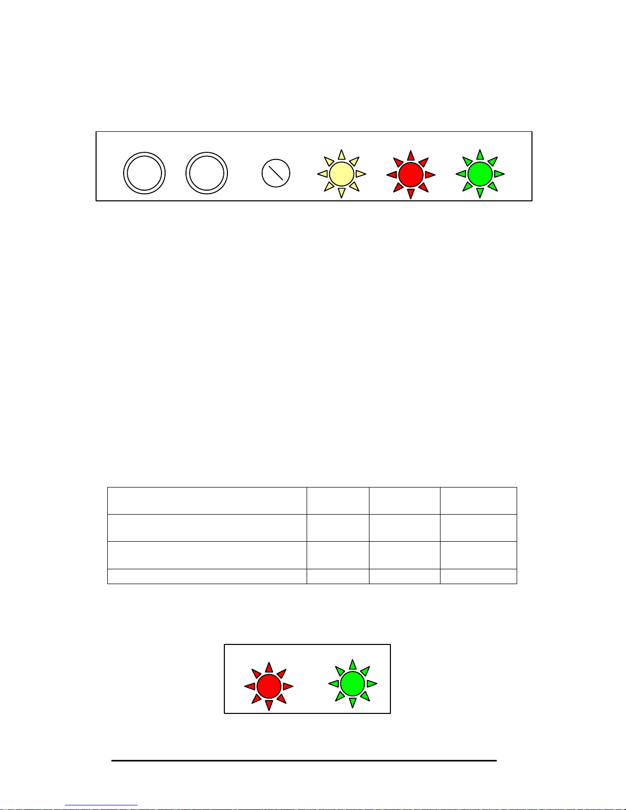
PQFA Instructions Manual
Asea Brown Boveri Jumet S.A.
67
10.4. Buttons, lights and LED’s signification
10.4.1. Master cubicle.
?? Push buttons:
RUN: starts the PQFA
RESET: stops switching of the IGBTs and opens the
main circuit breaker
?? Local – remote switch: local or remote control of the filter. If remote is on,
the push buttons are not operational.
?? Lights:
ON (white): the PQFA controller is connected to the supply (auxiliary breaker
closed)
CLOSE (red): the power circuit breaker is closed (filter working)
OPEN (green): the power circuit breaker is open
Three light conditions are then possible:
ON
(white)
CLOSE
(red)
OPEN
(green)
No power connection (main and
auxiliary breakers open)
Controller connected (auxiliary
breaker closed, main breaker open)
?
?
Filter working (all breakers closed)
? ?
10.4.2. Slave cubicle
RESET
RUN LOC/REM
ON CLOSE
OPEN
CLOSE
OPEN
Page 68
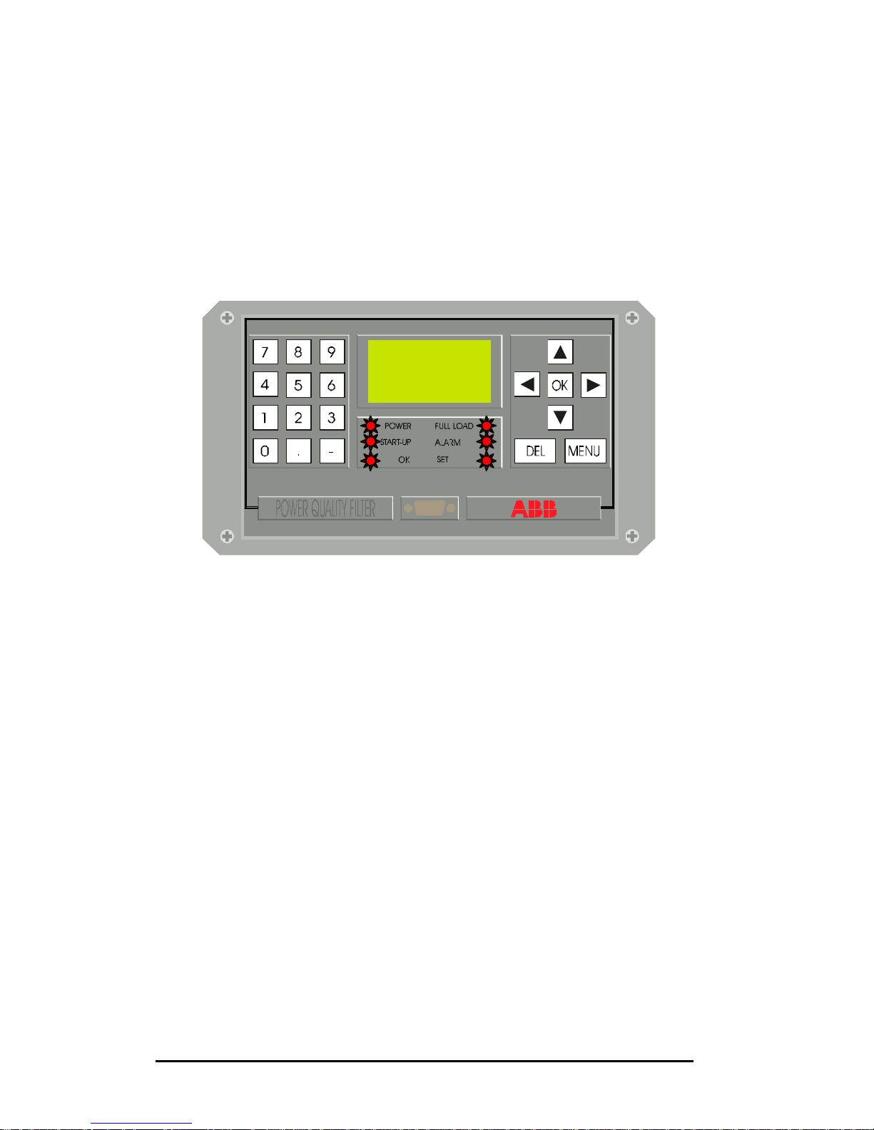
PQFA Instructions Manual
Asea Brown Boveri Jumet S.A.
68
?? Lights:
CLOSE (red): the power circuit breaker is closed (filter
working)
OPEN (green): the power circuit breaker is open
10.4.3. PQF-Manager
Red LED’s:
?? POWER: the controller is connected to the supply (auxiliary
breaker closed).
?? START-UP: the PQFA is in the start-up sequence.
?? OK: the PQFA is working properly and fulfilling
programmed requirements.
?? FULL LOAD: the filter is working at 100% of its nominal capacity
and programmed requirements are not fulfilled.
?? ALARM: the filter has stopped due to an error.
?? SET: the programming or set-up level of the PQF-
Manager has been activated.
The PQF-Manager is also fitted with a screw to adjust contrast. This screw is
situated on the back metal plate of the PQF-Manager.
Page 69
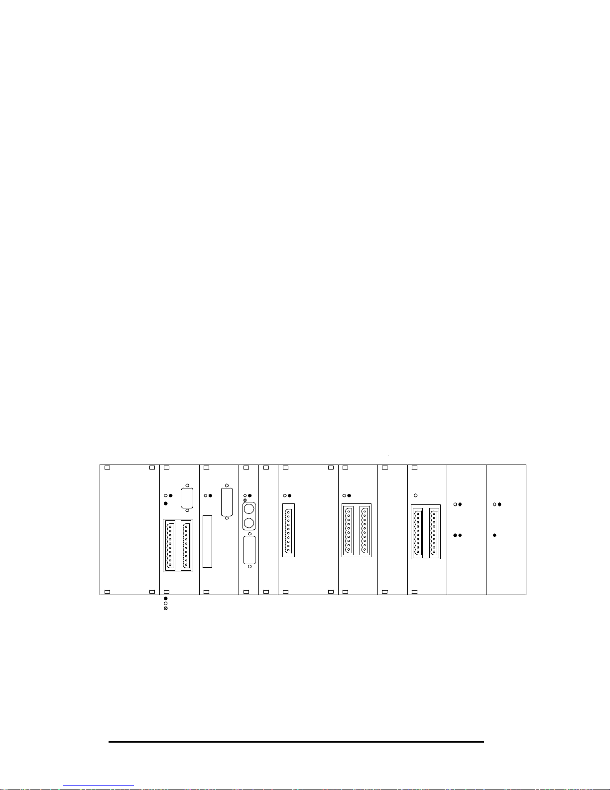
PQFA Instructions Manual
Asea Brown Boveri Jumet S.A.
69
10.4.4. Control rack.
A111 A112 A113 A119 A114 A115 A116 U100 U109
DIG
INT
DSP GUI LIC
LVI
ALIM/GND
±15V +5V
YELLOW LED
GREEN LED
RED LED
1 2
3
21
3
21 21 21 1
21 1 2
3 4 3
Board A111 DIG LED 1 (green) on: OK
LED 2 (red) on: malfunction
LED 3 (red) on: PQF synchronised on network
Board A112 INT LED 1 (green) on: OK
LED 2 (red) on: malfunction
Board A113 DSP LED 1 (green) and
LED 3 (yellow) blinking: OK
LED 2 (red) on: malfunction
Board A114 LIC LED 1 (green) on: OK
LED 2 (red) on: malfunction
Board A115 LVI LED 1 (green) on: OK
LED 2 (red) on: malfunction
Board U100 LED 1 (green) on: OK
LED 2 (red) on: power supply inhibited
LED 3 (red) on: output 1 inhibited
LED 4 (red) on: output 2 inhibited
Board U109 LED 1 (green) on: OK
LED 2 (red) on: power supply inhibited
LED 3 (red) on: output 1 inhibited
Page 70

PQFA Instructions Manual
Asea Brown Boveri Jumet S.A.
70
10.5. Programming with PQF-Prog
10.5.1. Filter operation principle.
The filter can have three types of effect on the network:
?? Filter the selected harmonics until their magnitudes are close to zero
(Maximum Filtering);
?? Filter the selected harmonics until their magnitudes reach the
residual level permitted by the user (Filtering to Curve);
?? Produce or absorb reactive power.
The user can put the emphasis on one of the above effects by selecting the
filtering mode. The following table shows the three available modes:
Highest priority
level
Lowest priority level
Mode 1 Filtering to curve Maximum filtering Reactive
compensation
Mode 2 Filtering to curve Reactive
compensation
Maximum filtering
Mode 3 Filtering to curve Reactive
compensation
?
In Mode 1, the PQFA will first filter to the pre-programmed curve. Once the
requirements are fulfilled, remaining resources will be allocated to reducing
the selected harmonics as close as possible to zero. If further resources are
then available, reactive power compensation will be performed as required.
In Mode 2, the second priority after filtering to the curve is reactive power
compensation. Maximum filtering comes in third place.
In Mode 3, two levels are defined: filtering to curve and reactive power
compensation.
In any case, filtering to curve is always the first priority. The alarm contact is
activated (open) if the filtering to curve requirements are not fulfilled.
Figure 10.2 here after illustrates the principle of filtering to curve for one
particular harmonic order. The flexibility of the PQFA control is such that a
specific curve may be defined for each selected harmonic.
Page 71
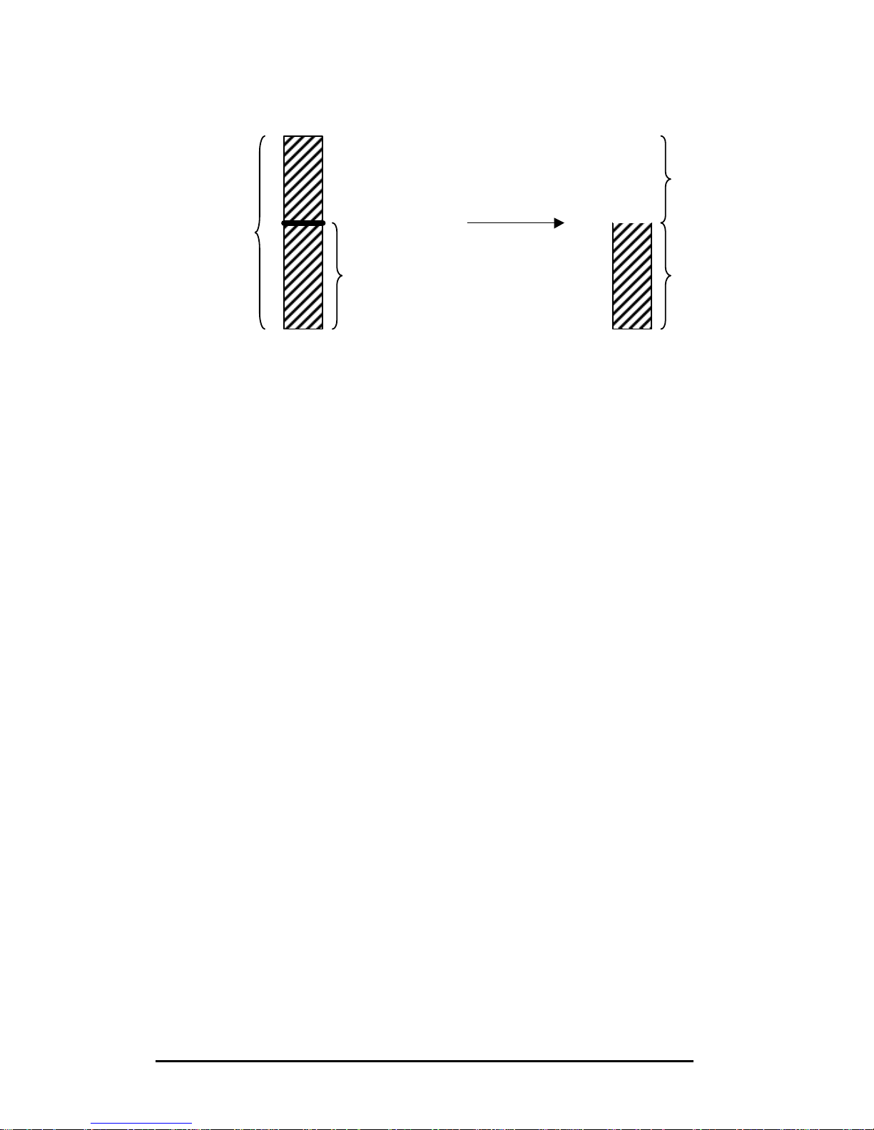
PQFA Instructions Manual
Asea Brown Boveri Jumet S.A.
71
Figure 10.2. Filtering to curve for harmonic order n
The programming procedure consists in:
1) Defining the Mode of operation.
2) Specifying the harmonics to be filtered and the permitted residual level
(=curve) for each of them. At 50 Hz, 20 harmonics between the 2nd and
50th may be selected. At 60 Hz, 15 harmonics between the 2nd and 50th.
3) Programming reactive power compensation parameters
10.5.2. Starting
Once the PQF-Prog software has been successfully installed (see chapter 7),
select Programs in the Start menu and click on PQF. If you did not install
PQF-Prog in the Program Files directory, create a shortcut to PQF_Prog.exe.
After launching PQF-Prog, a text box indicating that Station 0 has been found
will appear. Click ‘Done’. You then enter the PQF-Prog main Window.
In the Login box, type the User name and the password. Station must be “0”.
Filtered current
Remaining
current
Before filtering
After filtering
Permitted
residual level
=
curve
Load current
for harmonic
order n
Page 72
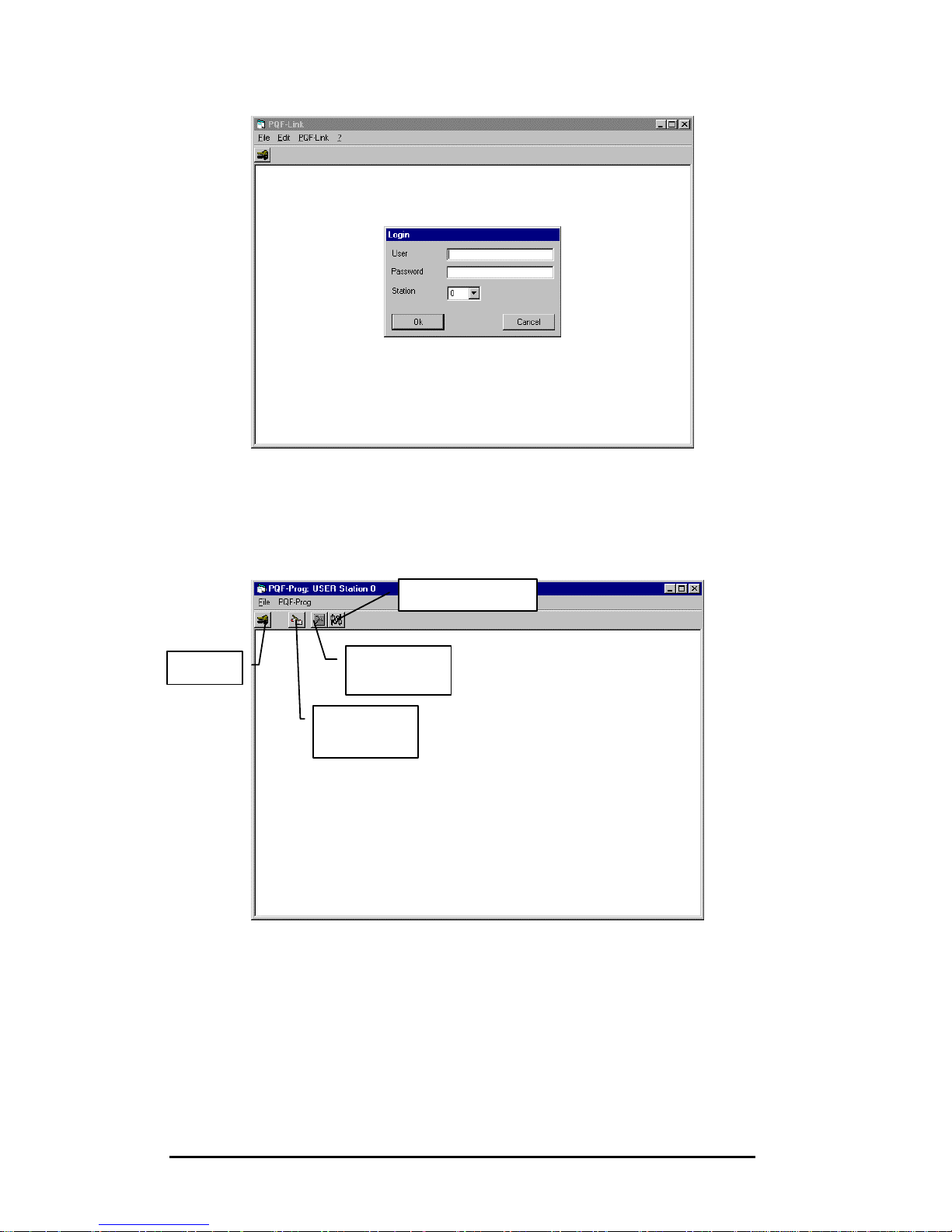
PQFA Instructions Manual
Asea Brown Boveri Jumet S.A.
72
If you use the appropriate User name and password, four icons appear on the
toolbar: Login, Filter Operation, Hardware set-up and Configuration.
If a wrong or no login is entered, you will only have access to the Login, Filter
Operation and Configuration icons.
Login
Filter
Operation
Hardware
set-up
Configuration
Page 73
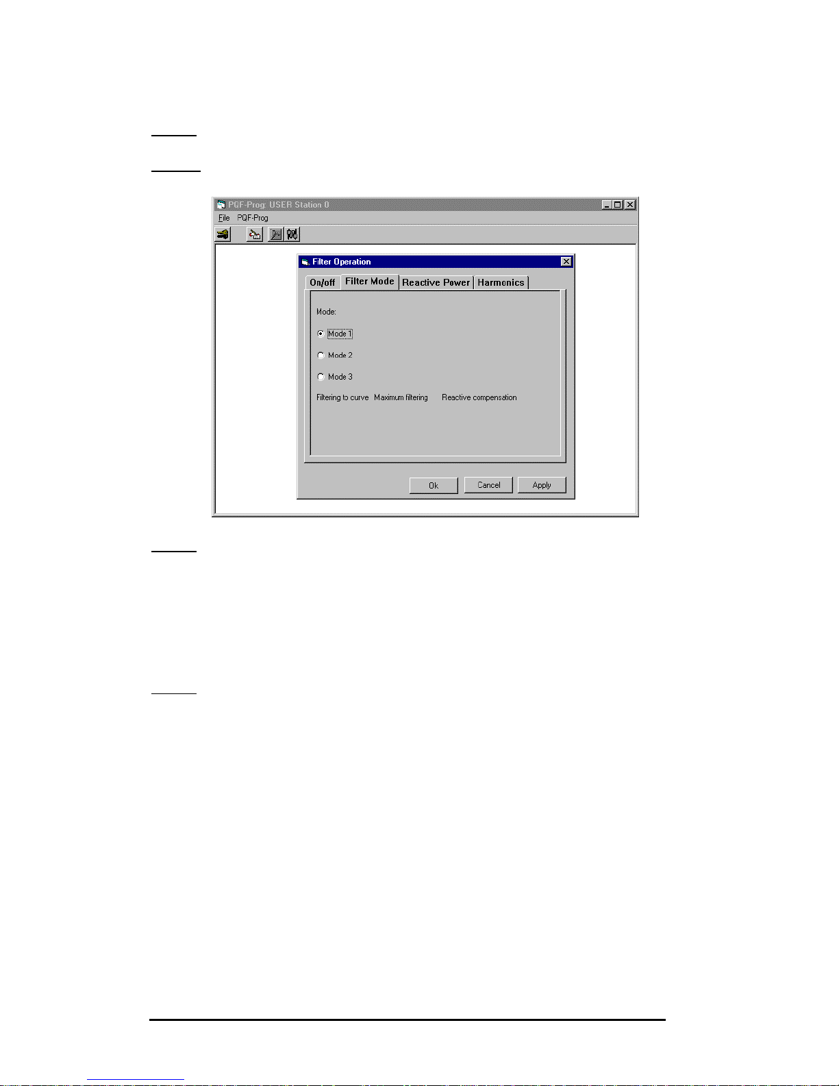
PQFA Instructions Manual
Asea Brown Boveri Jumet S.A.
73
10.5.3. Programming the filter
Step 1: click on the Filter Operation icon.
Step 2: Select the Filter Mode tab.
Step 3: Select the option button corresponding to your chosen mode of
operation. The priorities of the selected mode are indicated at
the bottom of the window.
Click on ‘Ok’ if you wish to save your choice and leave the Filter
Operation mode. Click on ‘Apply’ if you wish to validate your
choice and stay in Filter Operation mode.
Step 4: Select the Harmonics tab.
In order to select a harmonic order, enter Y (yes) in the second
column. N (no) indicates that the corresponding harmonic has
not been selected.
The curve may be programmed in absolute terms (Amps), in %
of the fundamental current or in % of the rms current.
After choosing your appropriate reference by using the option
button, program your target in the third column for the harmonics
you have selected. The values there entered constitute the curve
and the first priority of your PQFA will be to filter harmonics until
each selected order becomes lower than its specified target.
Click on ‘Ok’ if you wish to save your choice and leave the Filter Operation
mode. Click on ‘Apply’ if you wish to validate your choice and stay in Filter
Operation mode.
Page 74
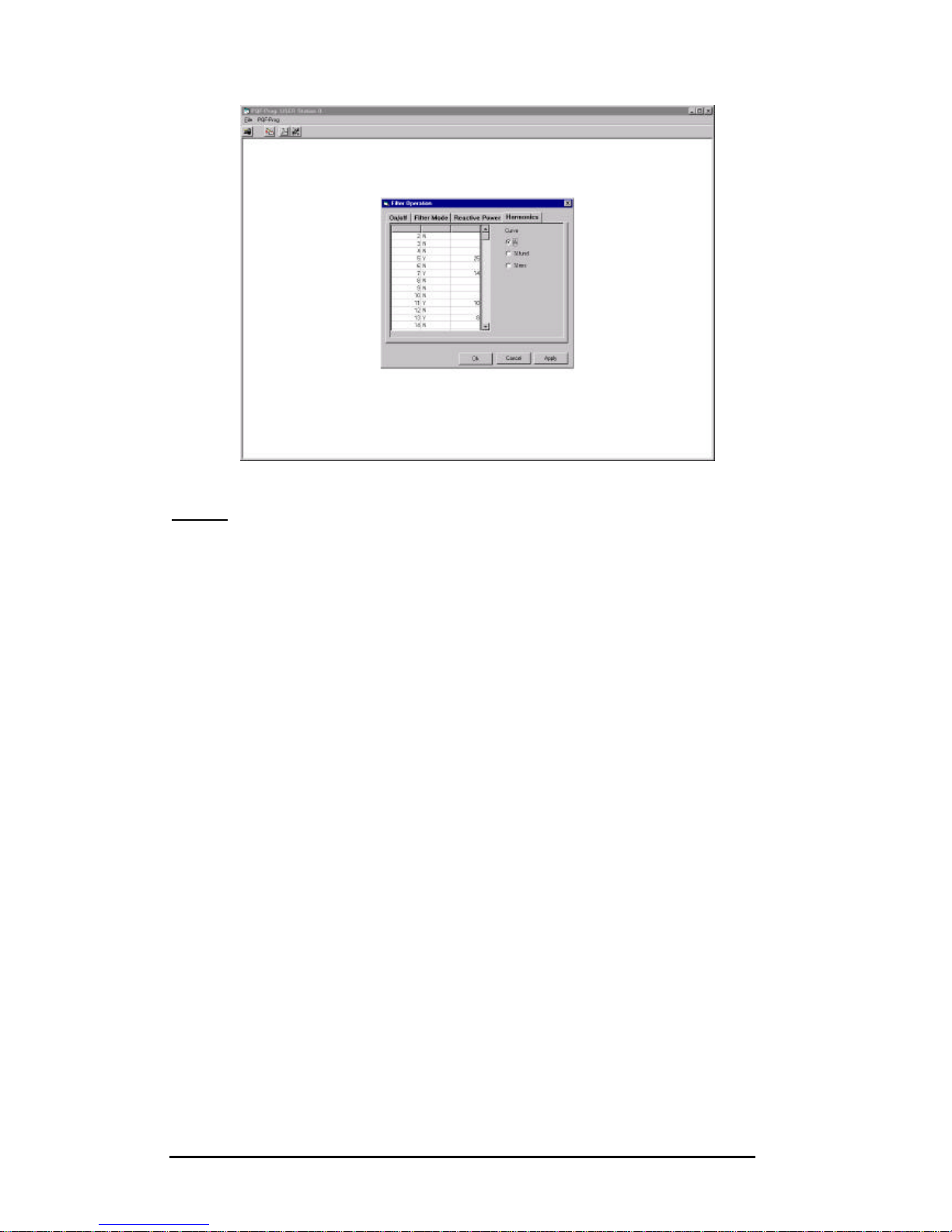
PQFA Instructions Manual
Asea Brown Boveri Jumet S.A.
74
Step 5: The filter may be switched on or off from the On/off tab.
Page 75

PQFA Instructions Manual
Asea Brown Boveri Jumet S.A.
75
10.6. Programming with PQF-Manager
10.6.1. Filter operation principle.
The filter can have three types of effect on the network:
??Filter the selected harmonics until their magnitudes are close to
zero (Maximum Filtering);
??Filter the selected harmonics until their magnitudes reach the
residual level permitted by the user (Filtering to Curve);
??Produce or absorb reactive power.
The user can put the emphasis on one of the above effects by selecting the
filtering mode. The following table shows the three available modes:
Highest priority
level
Lowest priority level
Mode 1 Filtering to curve Maximum filtering Reactive
compensation
Mode 2 Filtering to curve Reactive
compensation
Maximum filtering
Mode 3 Filtering to curve Reactive
compensation
?
In Mode 1, the PQFA will first filter to the pre-programmed curve. Once the
requirements are fulfilled, remaining resources will be allocated to reducing
the selected harmonics as close as possible to zero. If further resources are
then available, reactive power compensation will be performed as required.
In Mode 2, the second priority after filtering to the curve is reactive power
compensation. Maximum filtering comes in third place.
In Mode 3, two levels are defined: filtering to curve and reactive power
compensation.
In any case, filtering to curve is always the first priority. The alarm contact is
activated (open) if the filtering to curve requirements are not fulfilled.
Figure 10.3 here after illustrates the principle of filtering to curve for one
particular harmonic order. The flexibility of the PQFA control is such that a
specific curve may be defined for each selected harmonic.
Page 76
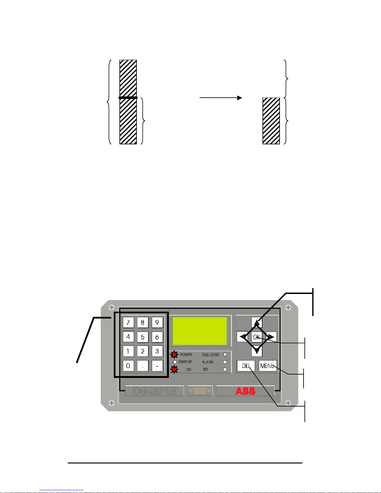
PQFA Instructions Manual
Asea Brown Boveri Jumet S.A.
76
Figure 10.3. Filtering to curve for harmonic order n
The programming procedure consists in:
1) Defining the Mode of operation.
2) Specifying the harmonics to be filtered and the permitted residual level
(=curve) for each of them. At 50 Hz, 20 harmonics between the 2nd and
50th may be selected. At 60 Hz, 15 harmonics between the 2nd and 50th.
3) Programming reactive power compensation parameters
10.6.2. Keys identification.
Filtered current
Remaining
current
Before filtering
After filtering
Permitted
residual level
=
curve
Load current
for harmonic
order n
Numerical
keypad
Arrow
buttons
‘OK’
button
‘MENU’
button
Delete
button
Page 77

PQFA Instructions Manual
Asea Brown Boveri Jumet S.A.
77
10.6.3. Programming the filter.
Step 1: The 3 levels of the PQF-Manager are accessible from the
window “Main menu”.
To enter the “Main menu” window, press MENU.
Level 1 is for consulting, level 2 for filter programming and level
3 for commissioning.
Select level 2 by pressing once the ? key.
Then press OK and enter the appropriate password for level 2.
The LED ‘SET’ will switch on.
Step 2: Three options appear in the level 2 window: mode, harmonics
and Q compensation.
Select Mode by using the ? key.
Press OK.
Step 3: Select your preferred mode of operation with the ? key. The
priorities of the selected mode are indicated on the window.
MAIN MENU
Level 1
?Level 2?
Level 3
LEVEL 2
?Mode?
Harmonics
Q compensation
FILTER MODE
MODE 1 2 3
FILTERING TO CURVE
MAX FILTERING
Q COMPENSATION
Page 78

PQFA Instructions Manual
Asea Brown Boveri Jumet S.A.
78
The selected mode only becomes operational once you press the OK button.
Step 4: Press on ‘MENU’ to come back to level 2 main window, select
‘harmonics’ by using the ? key and press OK.
In the next window, you have to specify the unit in which the
permitted residual level (= curve) is expressed. Three
possibilities are offered: amps ’A’, percentage of the
fundamental magnitude ’%I1’ and percentage of the RMS
current ’%Irms’.
Make your choice with the ? key and press OK.
You will then enter in the Harmonics window.
FILTER MODE
MODE 1 2 3
FILTERING TO CURVE
Q COMPENSATION
MAX FILTERING
FILTER MODE
MODE 1 2 3
FILTERING TO CURVE
Q COMPENSATION
LEVEL 2
Mode
? Harmonics ?
Q compensation
Page 79

PQFA Instructions Manual
Asea Brown Boveri Jumet S.A.
79
HARMONICS
CURVE :
A
ORDER SELECT CURVE
5 Yes 10
7 No 7
11
Yes
5
Use the ?? keys to select an order and press ‘OK’ to activate
the corresponding line.
Once the line is activated, you may modify the order number by
using the DEL button to delete the current value and the
numerical keypad of the PQF-Manager to enter the new value.
Press ‘OK’ to activate the Select column of the line. Use the ?
button to switch between ‘Yes’ and ‘No’.
Press ‘OK’ to activate the Curve column of the line and use the
numerical keypad to enter your filtering objective.
Once your parameters are entered, press ‘OK’ to activate your
programming for the correspondent harmonic order.
You can select and programme each individual harmonic by
using the ?? keys and following the same procedure.
Step 5: Press on ‘MENU’ to come back to level 2 main window, select ‘Q
compensation’ by using the ? key and press OK.
In the first window, you have to specify whether reactive power
compensation is requested.
Use the ? key to make your choice and press ‘OK’ to validate.
LEVEL 2
Mode
Harmonics
? Q compensation ?
Page 80

PQFA Instructions Manual
Asea Brown Boveri Jumet S.A.
80
If ‘ON’ is selected, you have to specify the type of reactive power
compensation: static or dynamic. Use the ? key to make your
choice and press ‘OK’ to validate.
If you select static compensation, you have to specify the
amount of fixed reactive power (kvar) that is requested. A
positive value means a capacitive injection while a negative
value means an inductive consumption.
If you select dynamic compensation, you have to specify the
target cos? in the range 0.6 inductive to 0.6 capacitive.
Press ‘ON’ to activate your choice.
Step 6 Return to the main menu by pressing the ‘MENU’ button.
Q COMPENSATION
Q COMP: OFF
Q COMPENSATION
Q COMP: ON
Q COMP: STEADY
Q : 50
Q COMPENSATION
Q COMP: ON
Q COMP: DYNAMIC
TARGET : 0.96
Page 81

PQFA Instructions Manual
Asea Brown Boveri Jumet S.A.
81
10.7. PQFA and network monitoring with the PQF-Manager
The 3 levels of the PQF-Manager are accessible from the window “Main
menu”.
To enter the “Main menu” window, press MENU.
Level 1 is for consulting, level 2 for filter programming and level 3 for
commissioning.
Select level 1 by using once the ? key.
Then press OK.
The consulting level gives you access to 4 submenus: the filter status, the
network status, the waveform and the spectrum.
To select one of those submenus, use the ? key and press OK.
10.7.1. Filter status.
In the Consulting level window, select Filter status and press OK.
A horizontal bar graph appears. It depicts the percentage of the filter
capabilities used as represented on figure 10.4.
MAIN MENU
?Level 1?
Level 2
Level 3
LEVEL 1
?Filter status?
Network status
Waveform
Spectrum
Page 82

PQFA Instructions Manual
Asea Brown Boveri Jumet S.A.
82
0% 100%75%
Figure 10.4. Filter Status Window
If you press the ? key, you display a second window listing the value of each
limiting factor:
- The percentage of use of the DC voltage capability;
- The percentage of use of the peak current capability;
- The percentage of use of the RMS current capability;
This second window also displays the error code if applicable.
You can easily switch between the 2 Filter Status windows with the ?? keys.
To come back to the Consulting level menu from any of those windows, press
MENU.
10.7.2. Network status
In the Consulting level window, select Network status and press OK.
The following window appears:
LEVEL 1
Filter status
? Network status?
Waveform
Spectrum
Page 83

PQFA Instructions Manual
Asea Brown Boveri Jumet S.A.
83
NETWORK STATUS
U
1-2
= 396 V
I1 = 654 A
THDU1 = 17 %
THDI1 = 74 %
Figure 10.5. Network Status
It gives you the RMS voltage between L1 and L2, the RMS current in L1 as
well as the Total Harmonic Distortion on the same voltage and current.
By pressing the ? key, you enter the second window displaying the RMS
voltage between L2 and L3, the RMS current in L2 as well as the Total
Harmonic Distortion on the same voltage and current.
If you press once more the ? key, you enter the third and last window with
the values of the RMS voltage between L3 and L1, the RMS current in L3 as
well as the Total Harmonic Distortion on the same voltage and current.
You can easily switch between those 3 windows with the ?? keys.
Press MENU and you come back to the consulting level menu.
10.7.3. Waveform
In the Consulting level window, select Waveform and press OK.
The first Waveform window proposes a choice of 3 submenus: the network
voltage, the line current and the filter current. Select the waveform you want to
display with the ? key and press OK.
Before displaying the waveform, you still have to choose the phase you want
to visualise. You can make your selection in the next window with the ? key
and you validate by pressing OK.
You then see the waveform you have selected.
LEVEL 1
Filter status
Network status
?Waveform ?
Spectrum
Page 84

PQFA Instructions Manual
Asea Brown Boveri Jumet S.A.
84
Un2
(V)
512
-512
Figure 10.6. Waveform Window
The graph indicates the unit, the waveform as well as the maximum positive
and negative values of the scale.
Press MENU and you come back to the Consulting level MENU.
10.7.4. Spectrum
In the Consulting level window, select Spectrum and press OK.
The first Spectrum window proposes a choice of 3 submenus: the network
voltage, the line current and the filter current. Select the spectrum you want to
display with the ? key and press OK.
Before displaying the spectrum, you still have to choose the phase you want
to visualise. You can make your selection in the next window with the ? key
and you validate by pressing OK.
You then see the spectrum you have selected.
LEVEL 1
Filter status
Network status
Waveform
?Spectrum ?
Page 85
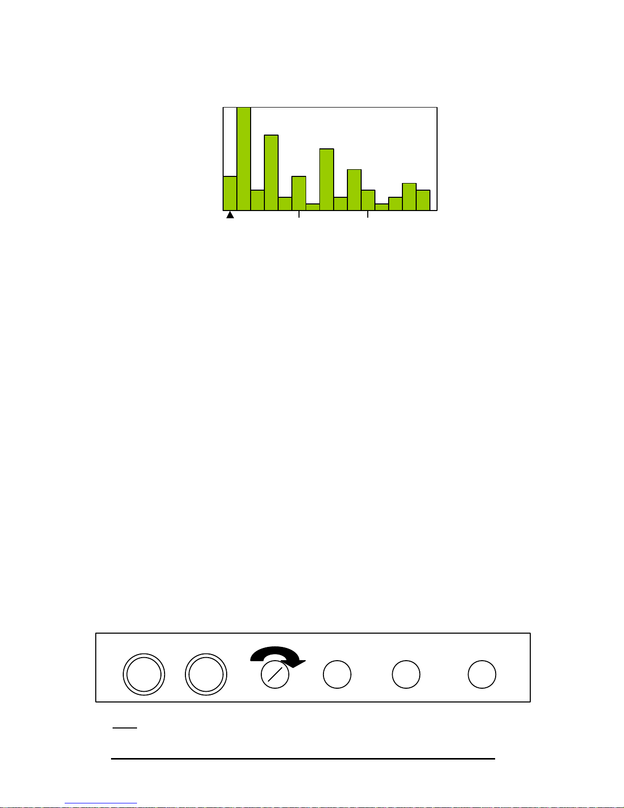
PQFA Instructions Manual
Asea Brown Boveri Jumet S.A.
85
60 A
H: 0
15 A
I
n1
Figure 10.7. Spectrum Window
The graph indicates the maximum value of the scale. In the above right
corner, you have the rank (0 is for DC) and the value in amps for the
harmonic identified with the arrow (?).
Press the ? or ? key to shift your selected harmonic of one order. If you
want to move faster in the spectrum, you can use the ? or ? key. You will
then shift of 15 orders.
Press MENU and you come back to the Consulting level MENU.
10.8. Remote control and alarm contact
10.8.1. Remote control
The PQFA may be switched on and off from a remote location.
The remote switch has to be connected to connection points X12-3 and X12-4
of terminal marked X12. In this configuration, applying a voltage to the points
X12-3 and X12-4 will switch on the filter. It will switch off when the voltage is
removed.
The remote/local switch of the master cubicle door has to be switched in
remote position.
Note: once remote is on, the push buttons of the door are not operational
anymore.
RESET
RUN LOC/REM
ON CLOSE
OPEN
Page 86

PQFA Instructions Manual
Asea Brown Boveri Jumet S.A.
86
10.8.2. Alarm contact
The PQFA is fitted with a normally open alarm contact (voltage free contact)
allowing remote supervision of the unit. It is open if one of the following
conditions is met:
?? The filter is in error condition
?? The filter is off
When it is closed the filter is working properly.
The exterior alarm has to be connected to connection points X12-1 and X12-2
of terminal X12.
10.9. Protections
The PQFA is fitted with two types of protection:
?? Slow protection
?? Fast protection
The role of the slow protection is to change on-line the way the filter is
working according to the filter stress and programmed levels. This ensures
that the filter is never overloaded and always has an optimal filtering effect.
The fast protection is only activated in case of abnormal working conditions
and ensures the integrity of the filter.
The fast protection means include:
1. Preventing the main breaker from closing in the event that the filter
– cannot synchronise to the supply network (e.g. wrong phase rotation
order)
– detects a permanent AC undervoltage on one of the feeding phases
– detects a permanent internal error generated by e.g. a wrong internal
flat cable connection, an excessively high level measured on the voltage
or current input channels, a faulty IGBT-module etc.
2. A blocking system of the IGBT-bridge in case of one occurrence of the
following events
– AC overvoltage on the mains detected by the hardware protection
system
– DC overvoltage on the DC capacitors detected by the hardware
protection system
– Filter overcurrent detected by the hardware protection system
– IGBT Overcurrent detected by the IGBT’s internal control logic
– IGBT Overtemperature detected by the IGBT’s internal control logic
Page 87

PQFA Instructions Manual
Asea Brown Boveri Jumet S.A.
87
3. When the filter is running, opening of the main incoming circuit breaker
when
– one of the above named events persists
– the breaker detects an overcurrent
– the system detects an AC undervoltage
– the system desynchronises from the network
– the system detects a DC capacitor over- or undervoltage
– an internal controller problem is encountered
A short-circuit/overcurrent protection on RMS and peak value internal to the
IGBT-modules
Page 88
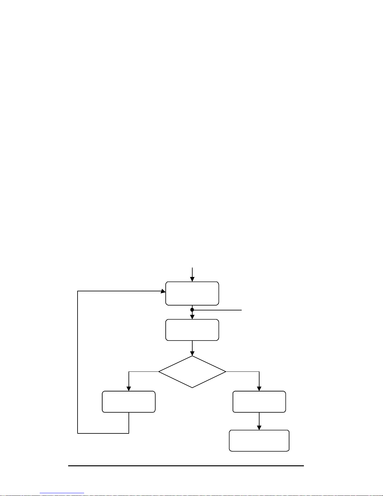
PQFA Instructions Manual
Asea Brown Boveri Jumet S.A.
88
11.Fault handling and troubleshooting
11.1. Fault handling
11.1.1. Type of faults
Faults are classified into two basic families:
?? Minor faults
?? Critical faults
Immediately after the fault occurrence, the error is cleared. If it has
disappeared, the fault is said minor. In the other case, the fault is considered
as critical.
11.1.2. Fault handling and fault clearance procedure
After the occurrence of a fault, the IGBT’s are stopped and the filter
determines the type of fault it is facing.
If it is not critical, the IGBT’s are restarted and the filter is back to normal
operation.
If the fault is critical, it is memorised and the filter conducts a fault clearance
procedure.
Fault handling procedure:
Normal
operation
Stop IGBT
Fault occurrence
Critical fault?
Memorise fault
Fault clearance
procedure
Start IGBT
Y
N
Page 89
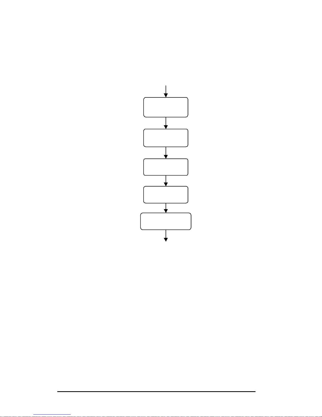
PQFA Instructions Manual
Asea Brown Boveri Jumet S.A.
89
The fault clearance procedure starts with the opening of the power circuit
breaker. The system is reset and the filter conducts again the start-up
sequence as shown hereafter. The fault message can be accessed through
the PQF-Manager.
If within 30 seconds after the re-start of the IGBT’s no critical fault occurs, the
initial fault is cleared and the filter comes back to normal operation.
If a critical fault occurs during those 30 seconds, either it is a different fault
than previously and a new fault clearance procedure is conducted or it is the
same fault.
If it is the same fault, a fault clearance procedure will be re-conducted until the
same fault is detected 5 consecutive times.
In this case, the power breaker is opened, the filter definitively stopped and
the alarm led on the PQF-Manager is lit. The error message can be accessed
through the PQF-Manager.
This procedure is shown in the next page.
Start fan
for 10s
Preload
DC bus
Close MC
Start IGBT
Network
characterisation
Page 90
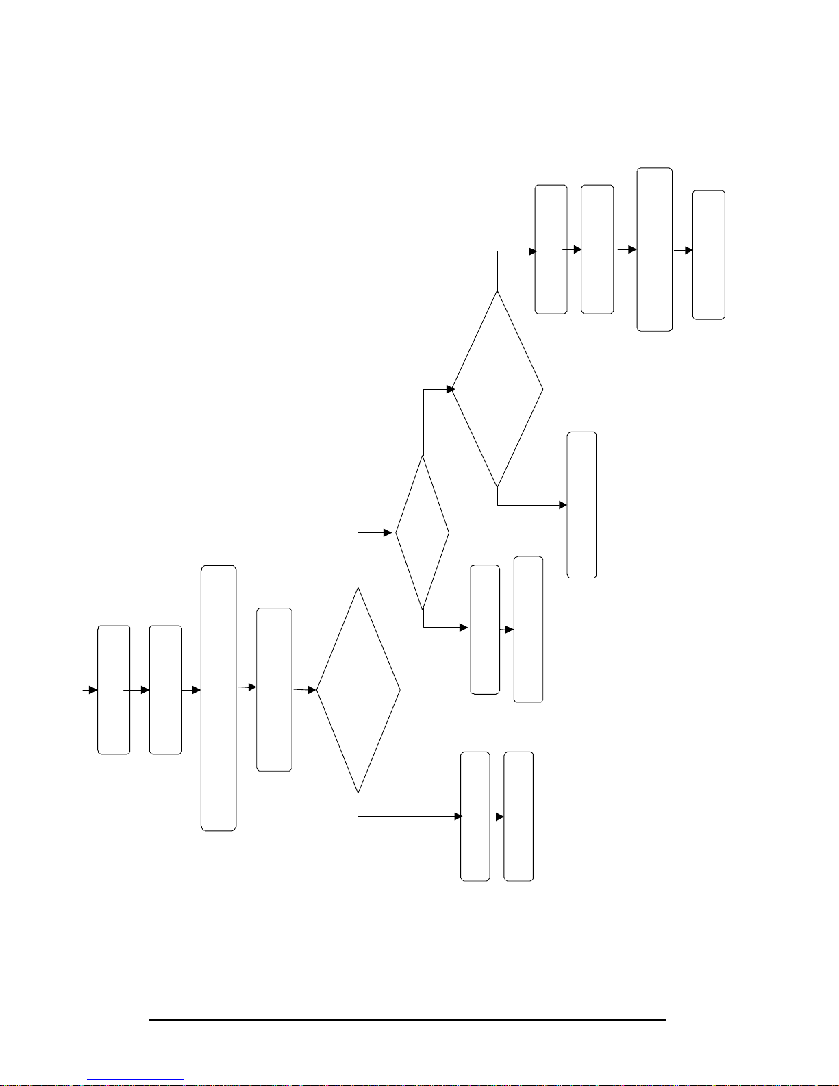
PQFA Instructions Manual
Asea Brown Boveri Jumet S.A.
90
System reset
Start-up
sequence
Critical fault
occurrence
within 30s
?
fault
Fault clearance
procedure
Fault cleared
YNOpen MC
Normal
operation
Same fault
as before
5th successive
fault ?
Fault clearance
Definitive stop
on PQF-Manager
Open MC
N
NYY
Display fault
msg (PQF Manager)
Alarm ON
Page 91

PQFA Instructions Manual
Asea Brown Boveri Jumet S.A.
91
11.2. Troubleshooting
11.2.1. Frequent problems occurring at commissioning stage
Problems occurring at commissioning stage are mainly due to wrong CT
connection or CT bridges not removed. Check carefully those connections in
accordance with the commissioning procedure.
FAULT Possible causes Solutions
No filtering nor reactive
power compensation
- All CT’s are in
correct phases but
some are reversed
- Wrong phase
rotation
- CT bridges not
removed
- Check carefully CT
wiring
- Remove CT bridges
on CT secondary
and PQFA terminal
input
No dynamic reactive
power compensation
All CT’s are in correct
phases but all are
reversed
- Modify CT
connection
accordingly, or
- Reversed CT’s may
be corrected by
software: a negative
CT ratio has to be
specified.
11.2.2. Error codes and messages
After a filter trip, an error message is displayed on the PQF-Manager. At the
same time, the corresponding error code is stored in the filter controller’s
permanent memory. The error codes can be accessed by PQF-Prog users
that have the appropriate password such as ABB service personnel. Below is
explained how the error messages can be accessed with the PQF-Manager.
If your filter is not fitted with this option, contact your ABB service provider for
further support.
In order to access the error code in the PQF-Manager, press MENU to access
the “Main menu” window.
Select level 1 by using once the ? key.
Then press OK.
MAIN MENU
?Level 1?
Level 2
Level 3
Page 92
PQFA Instructions Manual
Asea Brown Boveri Jumet S.A.
92
Select the filter status submenu with the ? key and press OK.
Display the ? key to display the error message.
The following table gives an overview of the error messages and codes that
can be encountered, the possible causes and the recommended actions.
Error
code
Error message Possible causes Actions
1 IGBT fault ?? Too high IGBT
temperature (thermal
protection)
?? Too high
instantaneous current
level (short-circuit
protection)
?? Supply voltage of
IGBT drivers too low
?? Visual inspection of
IGBT bridge
?? After checking bridge
condition, push on
the ‘RESET’ button of
the door. If the red
LED on the IGBT
domino board
remains on, contact
immediately your
ABB service provider
?? Check correct
rotation of fan,
associated contactor
(K101) and thermal
relay.
2 Filter over-
current
Too high output current
of the filter (short-circuit
protection)
?? Inspect IGBT bridge
?? Inspect ? 15V power
supply (U100)
?? Inspect internal
current sensors
(B101/102/103)
3 AC overvoltage Grid voltage rises to
unacceptable levels
Measure AC RMS
voltage for the three
phases and check if it is
within limits
LEVEL 1
?Filter status?
Network status
Waveform
Spectrum
Page 93

PQFA Instructions Manual
Asea Brown Boveri Jumet S.A.
93
Error
code
Error message Possible causes Actions
4 DC overvoltage DC voltage on DC bus
reaches unacceptable
levels
?? Check DC capacitors
?? Inspect ? 15V power
supply (U100)
?? Inspect internal
current sensor
(B101/102/103)
?? Inspect visually DC
voltage divider and
wiring
5 Connection
fault
?? Flat cable between
the control rack and
IGBT driver is
disconnected or
wrongly connected.
?? Module number
setting on board
A112 does not
correspond to the
number of modules
really present.
?? The jumpers on the
last domino board
are missing or are on
the wrong domino.
?? Check flat cable
connections
?? Verify that only the
domino board of the
last power module is
fitted with jumpers
?? Check the number of
modules set on the
controller board A112
6 Power supply
fault
One of the auxiliary
power supplies is out of
service.
?? Check that no red
LED is on the control
rack (except LED 3 of
A111). If yes, call
your ABB service
provider.
?? Check fuses of power
supplies
7 Control board
fault
The microcontroller is
not working properly.
Contact immediately
your ABB service
provider.
8 CAN bus fault The internal
communication bus of
the PQFA is not working
properly.
Contact immediately
your ABB service
provider.
16 DSP pgm
corrupted
DSP program corrupted Contact immediately
your ABB service
provider.
32 Watchdog
timeout
Software in
unpredictable state.
Contact immediately
your ABB service
provider.
Page 94

PQFA Instructions Manual
Asea Brown Boveri Jumet S.A.
94
Error
code
Error message Possible causes Actions
96 Soft DC
overvoltage
DC voltage on DC bus is
out of normal range
(overvoltage)
?? Inspect ? 15V power
supply (U100)
?? Inspect internal
current sensor
(B101/102/103)
?? Inspect visually DC
voltage divider and
wiring
97 Soft DC
undervoltage
DC voltage on DC bus is
out of range
(undervoltage)
?? Inspect DC voltage
measurement circuit
?? Inspect ? 15V power
supply (U100)
?? Inspect internal
current sensor
98 Soft AC
undervoltage
AC voltage is out of
range (undervoltage)
?? Check network
voltages on three
phases voltage
?? Check AC
measurement circuit
99 Soft synchro
fault
The system
desynchronises from the
network
?? Check phase rotation
order of filter supply
?? Check network
frequency and
variation to see one
within acceptable
limits
?? Check voltage level
of the supply system
112 Preload
timeout
The preloading of the
DC bus takes an
abnormally long time.
Check preloading circuit
system.
113 DSP stopped
system
DSP decision to stop the
system.
Contact immediately
your ABB service
provider.
114 Main breaker
trip
?? Power breaker not
closed after being
energised
?? Undervoltage on AC
grid
?? Check auxiliary
contact of main
breaker and
associated circuit
?? Check that grid AC
voltage is high
enough (within
tolerance)
115 DSP bus fault The DSP has stopped
communicating
Contact immediately
your ABB service
provider.
116 EEPROM
corrupted
Internal memory
corrupted
Contact immediately
your ABB service
provider.
Page 95

PQFA Instructions Manual
Asea Brown Boveri Jumet S.A.
95
Error
code
Error message Possible causes Actions
117 PWM fault Internal timing problem Contact immediately
your ABB service
provider.
11.2.3. Faults not related to error codes
?? Unstable filter.
Check CT connection and the presence of plain capacitors. Bear in mind that
harmonics below the resonance frequency of capacitor banks must be
deselected (see chapter 10).
?? Filter tripping during network characterization.
In weak networks, it may happen that high harmonic orders could not be
characterized. Those orders should be deselected.
?? No display on PQF-Manager.
Adjust the contrast of the PQF-Manager. Open the front door of the PQFA
(main breaker open, auxiliary closed) and adjust the contrast screw located on
the back metal plate of the PQF-Manager.
?? Fan is stopped.
Stop the filter and wait for the capacitors to discharge. Check the mechanical
condition of the fan. If the fan does not seem to be mechanically blocked, rearm the protection (blue flag of the motor overload protection F101). Check
whether the current is below 5A.
?? No LED is on on boards A116, U100 or U109 (power supplies).
Remove the board and check fuse(s) condition. Replace them if needed.
11.2.4. Restarting the filter after fault correction
?? Press RESET button 2 times.
?? Press RUN button.
The filter will then start its start-up sequence and will attempt to work again.
Page 96

PQFA Instructions Manual
Asea Brown Boveri Jumet S.A.
96
12.Maintenance
Although your PQFA has been designed for minimum maintenance, the
following procedure should be carefully followed to insure the longest possible
life to your investment.
WARNING!
All maintenance work described in this chapter should only be undertaken by
a qualified electrician. The Safety Instructions section of this manual must be
thoroughly followed.
12.1. Maintenance frequency
Under normal working conditions and environment, maintenance every six
months is recommended.
In case of installation in a dirty or sandy environment, a more frequent
maintenance programme should be implemented.
12.2. Maintenance procedure
Step 1 Shut the filter down by pushing the ‘RESET’ button of the door
cubicle.
Open the auxiliary circuit breaker.
Wait at least 5 minutes for the discharge of DC capacitors.
Step 2 Cleaning
All dust deposits have to be removed from all parts, especially
the heatsink and fan.
Indeed,the heatsink picks up dust from the cooling air and The
PQFA might run into overtemperature faults if the heatsink is not
cleaned regularly.
Step 3 Check breakers condition
Step 4 Check tightness of all electrical connections
Step 5 Check condition of discharge resistor on power modules
Page 97

PQFA Instructions Manual
Asea Brown Boveri Jumet S.A.
97
Step 6 Check ambient temperature and equipment ventilation
operation.
Step 7 Restart the PQFA according to commissioning procedure.
12.3. Fan
The cooling fan lifespan is about 5 years, depending on usage and ambient
temperature.
Fan failure is often preceeded by increasing noise from the bearings and rise
of the heatsink temperature despite cleaning. It is recommended to replace
the fan once these symptoms appear.
12.4. Capacitors reforming
If the filter has been non-operational for more than one year, DC capacitors
must be reformed (re-aged) before use. Without reforming, capacitors may be
damaged at start-up.
Stocked or non-operational filters should be reformed once a year. The
method indicated below assumes that the filter is stocked in a clean and dry
environment.
To reform the capacitors, switch the power on for about 2 hours, with all
harmonics and reactive power deselected.
If the filter has been left more than 2 years without operation, please contact
your ABB service provider.
Page 98

While all care has been taken to ensure that the information
contained in this publication is correct, no responsibility can be
accepted for any inaccuracy. The Company reserves the right
to alter or modify the information contained herein at any time
in the light of technical or other developments. Technical
specifications are valid under normal operating conditions
only. The Company does not accept any responsibility for any
misuse of the product and cannot be held liable for indirect or
consequential damages.
SIM.040.6027G01 ed. 9 01-10
Asea Brown Boveri Jumet S.A.
Zoning Industriel de Jumet
B-6040 Charleroi, Belgium
Phone : +32 71 250 811
Fax : +32 71 344 007
 Loading...