

Page 1
PowerValue 11 6-10 kVA
User Manual
04-3628_ABB_PVA11_T_6-10kVA_EN_REV-B.doc
© Copyright 2016 ABB, All rights reserved.
Page 2

This page left intentionally blank
04-3628_ABB_PVA11_T_6-10kVA_EN_REV-B.doc Page 2/32 ABB
Modifications reserved
Page 3
OPERATIONS INSIDE THE UPS MUST BE PERFORMED BY A SERVICE ENGINEER FROM
THE SUPPLIER OR FROM AN AGENT AUTHORIZED BY THE SUPPLIER.
THE INSTRUCTIONS IN THIS MANUAL SHOULD BE FOLLOWED DURING INSTALLATION,
OPERATION AND MAINTENANCE OF THE UPS AND BATTERIES.
WARNING: DANGER OF ELECTRICAL IMPACT
NOTE: READ THE INFORMATION, IN ORDER TO AVOID EQUIPMENT DAMAGES
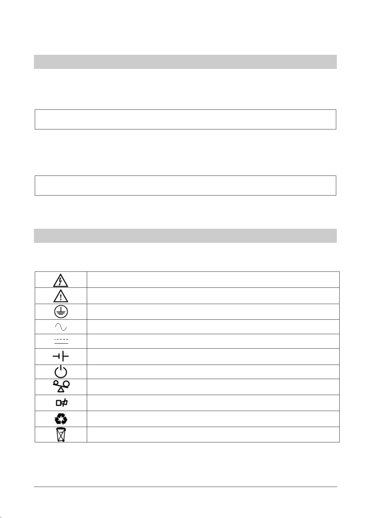
PROTECTIVE GROUNDING TERMINAL: A terminal which must be connected to earth
ground prior to making any other connection to the equipment
A terminal to which or from which an alternating current or voltage (AC) may be applied or
supplied
A terminal to which or from which a direct current or voltage (DC) may be applied or
supplied
Battery
Idle or shutdown the UPS
Overload indication
Alarm silence
Recycle
Do not dispose with ordinary trash
FOREWORD
The UPS System operates with mains, battery or bypass power. It contains components that carry
high currents and voltages. The properly installed UPS System is grounded to earth and IP 20 rated
against electrical shock and foreign objects.
This user manual contains guidelines to check delivery, installing and commissioning of the UPS
and is intended for people who plan the installation, install, commission and use or service the UPS.
The reader is expected to know the fundamentals of electricity, wiring, electrical components and
electrical schematic symbols.
Read carefully all instructions and save this manual for future reference.
SYMBOLS
The following symbols are used in this manual, the list below describes each symbol.
04-3628_ABB_PVA11_T_6-10kVA_EN_REV-B.doc Page 3/32 ABB
Modifications reserved
Page 4

CONTENTS
1 SAFETY INSTRUCTIONS ............................................................................................. 6
1.1 Operator precautions ................................................................................................................ 6
1.2 Environmental Considerations ................................................................................................... 6
1.3 Declaration of Safety conformity and CE marking ....................................................................... 6
1.4 Inquiries .................................................................................................................................... 7
1.5 Operation ................................................................................................................................. 7
1.6 Maintenance, servicing and faults .............................................................................................. 7
2 INSTALLATION ............................................................................................................ 8
2.1 Delivery, Transportation, Positioning and Storage ...................................................................... 8
2.1.1 Receipt of the UPS and visual inspection ................................................................................................... 8
2.1.2 Unpacking ................................................................................................................................................... 8
2.1.3 Storage of UPS ........................................................................................................................................... 8
2.2 Site Planning and Positioning ..................................................................................................... 9
2.2.1 Planning before the installation ................................................................................................................... 9
2.2.2 Positioning .................................................................................................................................................. 9
2.3 General Characteristics .............................................................................................................. 9
2.3.1 Rear View ................................................................................................................................................... 9
2.4 Electrical Installation ............................................................................................................... 10
2.4.1 Commissioning ......................................................................................................................................... 10
2.4.2 Recommended Cable Sections and Fuse Ratings .................................................................................... 10
2.5 Battery Connections (Model without internal batteries) ........................................................... 12
2.6 Emergency Power Off (EPO) ..................................................................................................... 13
2.7 Installation Checklist ............................................................................................................... 13
3 OPERATION ............................................................................................................... 14
3.1 Control Panel .......................................................................................................................... 14
3.1.1 Selection Keys .......................................................................................................................................... 14
3.1.2 LCD Display .............................................................................................................................................. 15
3.2 Turning On the UPS ................................................................................................................. 16
3.2.1 Turning on the UPS with mains ................................................................................................................. 16
3.2.2 Turning on the UPS without mains (Cold start) ......................................................................................... 16
3.3 Turning Off the UPS ................................................................................................................. 17
3.3.1 Turning off UPS with mains ....................................................................................................................... 17
3.3.2 Turning off UPS without mains ................................................................ ................................ .................. 17
3.4 Operating Mode ...................................................................................................................... 17
3.4.1 ECO Mode / High Efficiency Mode ............................................................................................................ 18
3.4.2 Converter Mode ........................................................................................................................................ 18
3.5 LCD Operation ......................................................................................................................... 19
3.5.1 Navigation ................................................................................................................................................. 19
3.6 Paralleling the units ................................................................................................................. 24
3.6.1 Installation and operation .......................................................................................................................... 24
3.6.2 Adding an UPS to an existing parallel system ........................................................................................... 26
3.6.3 Removing a Single UPS from a parallel system ................................ ........................................................ 26
4 COMMUNICATION ..................................................................................................... 27
4.1 Interface ................................................................................................................................. 27
4.1.1 USB........................................................................................................................................................... 27
4.1.2 Dry contact ................................................................................................................................................ 27
4.1.3 Intelligent Slot ........................................................................................................................................... 27
4.2 Monitoring Software ............................................................................................................... 27
5 MAINTENANCE .......................................................................................................... 29
6 TROUBLESHOOTING ................................................................................................ 30
04-3628_ABB_PVA11_T_6-10kVA_EN_REV-B.doc Page 4/32 ABB
Modifications reserved
Page 5

6.1 Fault identification and rectification ........................................................................................ 30
7 TECHNICAL SPECIFICATION ................................................................................... 32
04-3628_ABB_PVA11_T_6-10kVA_EN_REV-B.doc Page 5/32 ABB
Modifications reserved
Page 6
WARNING!
IT IS PROHIBITED TO REMOVE ANY SCREWS FROM THE UPS SYSTEM OR FROM
THE BATTERY CABINET: DANGER OF ELECTRICAL SHOCK.
WARNING!
HIGH FAULT CURRENTS (LEAKAGE CURRENTS):
BEFORE CONNECTING THE MAINS YOU MUST ENSURE THAT THERE IS A
PROPER EARTH CONNECTION!
WARNING!
THE USER MUST DISPLAY A WARNING SHIELD ON ALL PRIMARY UPS CIRCUIT
BREAKERS. THE SERVICE PERSONNEL HAS TO BE INFORMED ABOUT
DANGEROUS VOLTAGES. THE WARNING PANELS MUST CONTAIN THE
FOLLOWING TEXT: “ BEFORE STARTING WITH THE MAINTENANCE WORK ON
THE CIRCUIT BREAKERS , MAKE SURE THE UPS IS ISOLATED.”
1 SAFETY INSTRUCTIONS
1.1 Operator precautions
The user must follow the precautions and only perform the described operations. Also in these
measures the operator of the UPS System must adhere to the instructions in this manual. Any
deviations from the instructions could be dangerous to the user or cause accidental load loss.
The only user operations permitted are:
- Use of the LCD control panel (LCD Display) and Maintenance Bypass (if present)
- Start up and shut down of the UPS (excluding the commissioning start up)
- Operation of additional connectivity devices
THE SUPPLIER DOES NOT TAKE ANY RESPONSIBILITY FOR DAMAGES CAUSED THROUGH
WRONG MANIPULATIONS OF THE UPS SYSTEM.
1.2 Environmental Considerations
To operate the UPS at the best efficiency point, your installation site should meet the environmental
parameters outlined in this manual. Excessive amount of dust in the operating environment may
cause damage or lead to malfunction. The UPS should be always protected from the outside
weather and sunshine. The operating environment must meet the weight, airflow, size and clearance
requirements specified in the technical datasheet.
Under no circumstances the UPS should be installed in an airtight room, in the presence of
flammable gases, or in an environment exceeding environmental requirements here below.
An ambient temperature of +20°C to +25°C is recommended to achieve a long life of the UPS and
batteries. The cooling air entering the UPS must not exceed +45 °C and the humidity should be
below 95% (non-condensing).
1.3 Declaration of Safety conformity and CE marking
PowerValue 11 is designed, manufactured and commercialized in accordance with the standard EN
ISO 9001 of Quality Management Systems. The marking shows the conformity to the EEC Directive
by means of the application of the following standards in accordance with the specifications of the
harmonized standards:
• 2006/95/EC Low voltage directive.
• 2004/108/EC Electromagnetic Compatibility directive (EMC).
04-3628_ABB_PVA11_T_6-10kVA_EN_REV-B.doc Page 6/32 ABB
Modifications reserved
Page 7

Product Standards
Standards
Safety
EN 62040-1
EN 60950-1
Electromagnetic Compatibility (EMC)
EN 62040-2
EN 61000-4-2
EN 61000-4-3
EN 61000-4-4
EN 61000-4-5
EN 61000-4-6
EN 61000-4-8
EN 61000-4-11
EN 61000-2-2
Standards as reference:
• EN- 62040-1. Uninterruptible power supply (UPS). Part 1-1: General and safety requirements
for UPS’s used in accessible areas by end users.
• EN- 60950-1. IT equipment. Safety. Part 1: General requirements.
• EN- 62040-2. Uninterruptible power supply (UPS). Part 2: EMC requirements.
The suppliers responsibility is excluded in the event of any modification or intervention in the product
by the customer’s side.
Table 1: Standards
1.4 Inquiries
Address inquiries about the UPS to the local office or agent authorized by the supplier. Please note
the type code and the serial number of the equipment and contact your nearest agent authorized by
the supplier. The Code and the serial no. are shown on the nameplate of the product. For further
information on troubleshooting, go to Section 6.
1.5 Operation
Do not remove the enclosure of the UPS. This system is to be serviced by qualified service
personnel only.
Do not disconnect the mains cable from the UPS or the building wiring socket during operation as
this would remove the ground to the UPS and of all connected loads.
An integral single emergency switching device which prevents further supply to the load by the UPS
in any mode of operation should be provided in the building wiring installation.
An appropriate disconnect device as short-circuit backup protection should be provided in the
building wiring installation.
In order to fully disconnect the UPS, press the OFF button. Only after the UPS is shutdown,
disconnect the mains load.
Indiscriminate operation of switches may cause output loss or damage to equipment. Refer to
instruction before conducting any control.
While the UPSs work as a parallel system, the external parallel cable should be reinforced
insulation.
1.6 Maintenance, servicing and faults
Repairs may be carried out only by qualified maintenance personnel as the UPS operates with
hazardous voltages.
04-3628_ABB_PVA11_T_6-10kVA_EN_REV-B.doc Page 7/32 ABB
Modifications reserved
Page 8
WARNING!
EVEN AFTER THE UNIT IS DISCONNECTED FROM THE MAINS POWER
SUPPLY, COMPONENTS INSIDE THE UPS ARE STILL CONNECTED TO THE
BATTERY WHICH ARE POTENTIALLY DANGEROUS.
WARNING!
THE BATTERY CIRCUIT IS NOT ISOLATED FROM THE INPUT VOLTAGE.
HAZARDOUS VOLTAGES MAY OCCUR BETWEEN THE BATTERY TERMINALS
AND THE GROUND. VERIFY THAT NO VOLTAGE IS PRESENT BEFORE
SERVICING.
WARNING!
THE PLASTIC POLY-STRAPS AROUND THE SHIPPING CONTAINER ARE
UNDER TENSION. WHILE CUTTING, DO NOT FACE THEM AS THEY MAY
SPRING BACK AND CAUSE INJURIES.
Before carrying out any kind of service and/or maintenance, disconnect the batteries. Verify that no
current is present and no hazardous voltage exists in the capacitor or BUS capacitor terminals.
Batteries must be replaced only by qualified personnel.
When changing the batteries, replace with the same quantity and the same type of batteries.
Replace the fuse only by a fuse of the same type and of the same amperage in order to avoid fire
hazards.
2 Installation
2.1 Delivery, Transportation, Positioning and Storage
2.1.1 Receipt of the UPS and visual inspection
Upon receiving the UPS, carefully examine the packing container and the UPS for any sign of
physical damage. In case of damage, notify immediately the carrier.
The packing container of the UPS protects it from mechanical and environmental damage. To
increase its protection, the UPS is wrapped with a plastic sheet. Preserve the packaging for later reuse.
2.1.2 Unpacking
After examining the package, unpack the equipment by removing the packing and shipping
materials. Cut the plastic poly-straps around the shipping container and remove the corrugated
carton and the UPS foam on the top of the UPS. With one or two people on each side of the UPS,
lift the UPS out of the pallet. Keep the UPS always in upright position and do not drop the
equipment.
Examine the UPS for any sign of damage and ensure that the received UPS corresponds to the
material indicated in the delivery note. Notify your carrier or supplier immediately if damage is
apparent.
2.1.3 Storage of UPS
If you plan to store the UPS prior to use, keep the UPS in a dry, clean and cool storage room with an
ambient temperature between (-15 °C to +60°C) and humidity of less than 95% non-condensing. If
04-3628_ABB_PVA11_T_6-10kVA_EN_REV-B.doc Page 8/32 ABB
Modifications reserved
Page 9
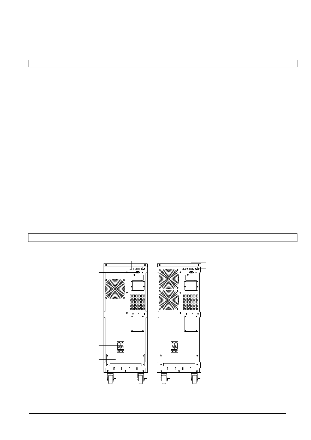
RS 232(optional)
EPO Port
Intelligent Slot
Parallel Port
Maintenance Switch
USB Port
Dry contact
Fan
Input Breaker
Terminal Block
6 kVA 10 kVA
the packing container has been removed protect the UPS from dust. Keep the UPS always in
upright position and do not drop the equipment.
2.2 Site Planning and Positioning
2.2.1 Planning before the installation
The appropriate place of installation for the unit is to be selected in such a way that the danger of
damage to the UPS is minimized and a long service life of the device is thus ensured. Please
observe the following instructions:
- Install the UPS in the indoor area.
- Leave 50cm of space on each side of the cabinet to enable cooling airflow and ensure that the
circulation of air to the ventilation slits is not obstructed.
- Avoid excessively high temperature and excessive moisture.
- Make sure that the floor surface is solid and suitable for the wheeling and weight.
2.2.2 Positioning
PowerValue 11 (6-10 kVA) have wheels that make the positioning of the UPS simple after it has
been unpacked. However, if the unpacking area is distant from the installation site, it is
recommended to transport the UPS with a forklift before unpacking the UPS.
It is recommended to install external battery cabinet(s) next to the UPS unit. Check before the
installation that the battery voltage values in the type plate of the UPS and external battery cabinets
are the same.
Water condensing may occur if the UPS is unpacked in a very low temperature environment. In this
case it is necessary to wait until the UPS is fully dried inside out before proceeding installation and
use to avoid hazards and electric shock.
2.3 General Characteristics
2.3.1 Rear View
04-3628_ABB_PVA11_T_6-10kVA_EN_REV-B.doc Page 9/32 ABB
Figure 1: UPS rear view
Modifications reserved
Page 10
WARNING!
OPERATIONS INSIDE THE UPS MUST BE PERFORMED BY A SERVICE
ENGINEER FROM THE SUPPLIER OR FROM AN AGENT AUTHORIZED
BY THE SUPPLIER.
DO NOT OPERATE IN CASE OF PRESENCE OF WATER OR MOISTURE.
BY OPENING OR REMOVING THE UPS-COVERS YOU ARE EXPOSED TO
DANGEROUS VOLTAGES.
PHYSICAL INJURY OR DEATH MAY FOLLOW, OR DAMAGE MAY OCCUR
TO THE UPS, OR THE LOAD EQUIPMENT IF THESE INSTRUCTIONS ARE
IGNORED
Model
6kVA
10kVA
Protective earth conductor
Minimum cross section
UL1015
6mm2 (8AWG)
UL1015
10 mm2 (6AWG)
Input L, N, G
Minimum conductor cross section
UL1015
3x6mm2 (8AWG)
UL1015
3x10 mm2 (6AWG)
Input breaker
40A/250VAC
63A/250VAC
Output L,N, G
Minimum conductor cross section
UL1015
3x 6mm2 (8AWG)
UL1015
3x 10 mm2 (6AWG)
External Battery Cabinet
Positive Pole(+), Negative pole(-), Neutral Pole
Minimum conductor cross section
UL1015
2x 6mm2 (8AWG)
UL1015
2x 10 mm2 (6AWG)
External Battery Cabinet Fuse
in Positive Pole(+), Negative pole(-), Neutral Pole
30A/240VDC
60A/240VDC
External Battery Cabinet Breaker
in Positive Pole(+), Negative pole(-), Neutral Pole
32A/240VDC
50A/240VDC
Torque for fixing above terminals
3.95~4.97Nm (35~44 1b in)
2.4 Electrical Installation
2.4.1 Commissioning
The UPS must be commissioned by a fully trained and authorized field service engineer before
being put into use. The commissioning of the UPS involves the connection of the UPS and batteries,
the verification of the electrical installation and operating environment of the UPS, the controlled
start-up and testing of the UPS and customer training.
To ensure correct operation of the UPS and its ancillary equipment it is necessary to provide the
mains cables with appropriate fuse protection.
2.4.2 Recommended Cable Sections and Fuse Ratings
Follow the recommendations in Table 2 or respect the local standards.
Table 2: Recommended Cables and Fuses
It is suggested to install an external isolating device against current back feed between Mains input
and UPS as indicated in Figure 2.
04-3628_ABB_PVA11_T_6-10kVA_EN_REV-B.doc Page 10/32 ABB
Modifications reserved
Page 11

WARNING!
AFTER THE DEVICE IS INSTALLED, ADD A LABEL WITH THE
FOLLOWING WARNING ON THE EXTERNAL AC CONTACTOR: “RISK OF
BACKFEED VOLTAGE. ISOLATE THE UPS BEFORE OPERATING ON
THIS CIRCUIT AND CHECK FOR HAZARDOUS VOLTAGE”
INPUT G
INPUT N
INPUT L
BATTERY +
BATTERY -
BATTERY G
OUTPUT G
OUTPUT L
OUTPUT N
PARALLEL JUMP2
PARALLEL JUMP1
IP_G IP_N IP_L B+ B- B_G J1 J2 OP_N OP_L OP_G
Figure 2: External Backfeed Isolation
The UPS unit has the following power connections:
Rectifier (In): 1 phase (input L), 1 Neutral (input N) and protective earth (input G)
connection for the rectifier input
Load (Out): 1 phase (output L), 1 Neutral (output N) and protective earth (output G)
connection for the load output
External battery: Plus (+), Minus (-) and protective earth (G) connection for the external batteries
Paralleling: Parallel Jumper 1 and 2
Figure 3: Terminal block wiring diagram
1 - The output of the UPS may be energized even if the UPS is turned off. To ensure that the UPS
has no power in the output, power off the UPS, and cut off the mains power supply. Wait the UPS
shut down completely.
2 - Open the terminal block cover located on the rear panel of UPS (refer to diagram on Section
2.3.1).
3 - Do not use the wall jack because its rated current is higher than the UPS maximum input current.
4 - Install the protective earth (ground) wire (refer to Figure 3). It is recommended to use green or
green/yellow wires.
5 - Connect the input and output wires to the corresponding terminals
Use appropriate tools and terminal splices to guarantee a reliable contact between the wires and the
terminal blocks.
Note:
- If the UPS is single in a system, JP1 and JP2 must be connected.
- If the UPS is used in parallel, the jumper between JP1 and JP2 must be removed.
04-3628_ABB_PVA11_T_6-10kVA_EN_REV-B.doc Page 11/32 ABB
Modifications reserved
Page 12

WARNING!
ANY INCOMPLIANCE MAY RESULT IN THE RISK OF ELECTRIC SHOCK.
FOLLOW THE INSTRUCTIONS
THE UPS CONTAINS HIGH DC VOLTAGES. A QUALIFIED PERSON MUST
DO THE CONNECTIONS BETWEEN THE UPS AND THE EXTERNAL
BATTERIES.
- The battery connectors are only used for the UPS using external batteries
6 - Install an output breaker between the output terminal of the UPS and the load. It is
recommended to use a breaker with leakage current protection.
7 - Turn off all the loads. Then connect the load to the UPS and finally turn on the loads one by one.
8 - After completing the steps above, check that all wires are connected correctly and tightly.
9 - Turn On the mains power switch and turn the input breaker to the On position. The UPS will
charge the batteries automatically. The UPS can be immediately used in inverter mode but it is
recommended to charge the batteries completely to guarantee the maximum back up time.
Note: The power consumption in the start-up of inductive loads (such as monitors and laser printers)
is very high. If such loads are connected to the UPS, the start-up power consumed by these devices
should be considered when calculating the capacity of the UPS. If this is not taken into
consideration, the UPS goes often in overload and may turn off easily depending on its
dimensioning.
2.5 Battery Connections (Model without internal batteries)
The nominal DC voltage of external battery pack is 240VDC. Each battery pack consists of 20
pieces of 12V maintenance free batteries in series. To achieve longer backup time, it is possible to
connect several battery packs, but the principle of “same voltage, same type” should be strictly
followed.
The external battery pack must be independent for each UPS. Two or more UPS cannot use the
same external battery pack.
Follow the steps below to connect the battery packs.
1 - Ensure the UPS is not powered on and the mains input breaker is set in the “OFF” position.
2 - A DC breaker must be installed between the external battery pack and the UPS. The capacity of
breaker must be higher than specified in the general specification.
3 - With the external battery pack breaker in “OFF” position, connect the 20 batteries in series.
4 - Connect the external battery pack to the battery terminals. Check the polarity if the connection is
correct.
5 - Turn the breaker of the battery pack to the “ON” position. The UPS will power on and start to
charge the battery pack.
04-3628_ABB_PVA11_T_6-10kVA_EN_REV-B.doc Page 12/32 ABB
Modifications reserved
Page 13

2.6 Emergency Power Off (EPO)
The EPO connector gives the user the possibility to block the output of the UPS in case of an
emergency. This connector can be configured as Normally Closed (NC) of Normally Opened (NO)
through the USD or RS232 port.
As a default the EPO is Normally Closed (NO) by a jumper in the rear panel. If the jumper is
removed, the UPS output will not supply energy to the load until the EPO status is again modified.
Enable the EPO status Disable the EPO status
To recover to normal status, the EPO connector should first be closed. Then, enter the LCD menu
(refer to Section 0) to clear the EPO status. The UPS alarm will stop and the bypass mode will be
recovered. To have the UPS in inverter mode, the selection has to be made by manual operation.
The polarity of connector could be inversed by setting in LCD menu as from section 0. Contact your
local supplier for further information before modifying the settings.
2.7 Installation Checklist
All packing materials and restraints have been removed from each cabinet.
Each cabinet in the UPS system is placed in the installed location.
All conduits and cables are properly routed to the UPS and auxiliary cabinets.
All power cables are properly sized and terminated.
A ground conductor is properly installed.
Battery cabinet installation instructions have been completed.
Air conditioning equipment is installed and operating properly.
The area around the installed UPS system is clean and dust-free.
Adequate workspace exists around the UPS and other cabinets.
Adequate lighting is provided around all UPS equipment.
Any optional accessories are mounted in their installed location and properly wired.
Summary alarms and/or building alarms are wired appropriately. (OPTIONAL)
Start-up and operational checks performed by authorized service personnel.
All network connections are completed.
04-3628_ABB_PVA11_T_6-10kVA_EN_REV-B.doc Page 13/32 ABB
Modifications reserved
Page 14

WARNING!
ONLY PERSONS WHICH HAVE BEEN TRAINED BY SERVICE
TECHNICIANS OF THE SUPPLIER OR HIS AUTHORIZED SERVICE
PARTNERS ARE ALLOWED TO OPERATE THE CONTROL PANEL OF
THE UPS.
ALL OTHER INTERVENTIONS ON THE UPS SYSTEM HAVE TO BE
DONE ONLY BY SERVICE TECHNICIANS OF THE SUPPLIER.
The
Button
Function
Illustration
Power on
If the unit is not powered and has the batteries connected, press this button for more
than 100ms and less than 1s to power on the UPS
Turn on
If the unit is powered on and is on Bypass mode, press this button for more than 1s to
turn on the UPS
Power off
If the unit is ON, press this button for more than 3s to turn off the UPS
Enter main
menu
If displaying the default UPS status screen, press this button for more than 1s to enter
the main menu tree
Exit main menu
Press this button for more than 1s to exit the present menu. Directs the user to default
system status menu without executing any command or changing settings
Scroll up
Press this button for >100ms&<1s to scroll up the menu option
Scroll down
Press this button for more than 100ms and less than 1s to scroll down the menu option
3 OPERATION
This chapter describes how to operate the UPS through the LCD display.
The only user permitted operations are:
Operate the LCD display
Start up and shut down of the UPS of the user field (excluding the commissioning start up)
Operation of additional SNMP adapters and their software
3.1 Control Panel
The user-friendly control panel is composed of two parts:
Selection Keys
Power Management LCD Display (PMD)
Figure 4: Control Panel
3.1.1 Selection Keys
04-3628_ABB_PVA11_T_6-10kVA_EN_REV-B.doc Page 14/32 ABB
Modifications reserved
Page 15

Enter next menu
tree
Press this button for more than 100ms and less than 1s to select the present menu
option or enter next menu. No settings are modified.
Select one
menu option
Press this button for more than 100ms and less than 1s to select the present menu
option or enter next menu. No settings are modified.
Confirm the
present setting
Press this button for more than 1s to confirm the edited options and change the settings
UPS state
Normal LED
(Green)
Battery LED
(Yellow)
Bypass LED
(Yellow)
Fault LED
(Red)
Bypass mode
with no output
- - C
D
Bypass mode
with output
- - A
D
Turning on
B B B
B
Line mode
A - -
D
Battery mode
A A -
D
HE mode
A - A
D
Battery test
mode
B B B
B
Fault mode
- - D
A
Warning mode
D D D
C
UPS condition
Buzzer status
Fault active
Continuous
Warning active
Beep every second
Battery output
Beep every 4 seconds, if battery low, buzzer Beep
every second
Bypass output
Beep every 2 minutes
Overload
Beep twice every second
3.1.2 LCD Display
The LCD display gives the user a complete overview on the status of the UPS. It shows information
on the input, output, battery, load parameters, working mode and also the settings on voltage,
frequency and bypass presence.
Figure 5: LED representation
A: Lightened constantly
B: LEDs 1 to 4 Lightened circularly
C: Flashing
D: Depends on the fault/warning status or other status
Figure 6: Definition of Alarms
When powering on, the LCD displays a welcome message for a few seconds and then enters the
default page that shows the UPS status.
From any screen, if the user does not press any button for more than 15 minutes, the default screen
is displayed.
The status screen provides the following information:
- Status summary, including operating mode and load information
- Alarm status, if any are present (including fault and warning information)
- Battery and charger status (including battery voltage, charge level and charger status)
- Running information including parallel UPS and running time
04-3628_ABB_PVA11_T_6-10kVA_EN_REV-B.doc Page 15/32 ABB
Modifications reserved
Page 16

Input
220 V
60 Hz
Output
220 V
60 Hz
5400 W
273.0 V
100%
Utility input
information
UPS output
information
Load information
Battery informationUPS operating status
WARNING!
SWITCH OFF THE CONNECTED LOADS BEFORE TURNING ON THE UPS.
SWITCH ON THE LOADS ONE BY ONE AFTER THE UPS IS TURNED ON.
Figure 7: The default LCD display
For detailed information on how to operate the LCD, see Section 3.5.
3.2 Turning On the UPS
3.2.1 Turning on the UPS with mains
1 - Check that all cables are connected correctly and well-fixed mechanically. Check that the
position of the breaker on the external battery pack is “ON”.
2 - Set input breaker to “ON” position. The fans are activated and the LCD shows a welcome screen.
The UPS then performs a self-test and finally displays the UPS status screen.
3 - Press the power-on button continuously for more than 1 second. The alarm buzzer will sound
for 1s and the UPS start-up will take place.
4 - After a few seconds, the UPS goes to Online mode. If the mains power is abnormal, the UPS will
transfer to Battery mode without interruption of the output the UPS.
3.2.2 Turning on the UPS without mains (Cold start)
1 - Check that all cables are connected correctly and well-fixed mechanically. Check that the
position of the breaker on the external battery pack
2 - Pressing the power-on button continuously for more than 100ms, the UPS is powered on. The
fan are activated and the LCD shows a welcome screen. The UPS then performs a self-test and
finally displays the UPS status screen.
3 - Pressing the power-on button continuously for more than 1s, the alarm buzzer sounds for 1s
and the UPS start-up takes place.
4 - After a few seconds, the UPS goes to Battery mode. When the UPS is fed with power from the
mains, the UPS transfers to Online mode without interruption in the output of the UPS.
04-3628_ABB_PVA11_T_6-10kVA_EN_REV-B.doc Page 16/32 ABB
Modifications reserved
Page 17

WARNING!
SWITCH OFF ALL OF THE CONNECTED LOADS BEFORE TURNING OFF THE
UPS
Input
220 V
60 Hz
Output
220 V
60 Hz
5400 W
273.0 V
100%
Operating mode
Status
Symbol
Description
Online Mode
UPS is running through the inverter (Online)
Battery Mode
UPS running on battery. (The alarm buzzer sounds every 4
seconds.)
Bypass with output
The power used by the load is supplied from the mains power
via internal filter. The UPS does not have the backup function
when it is in bypass mode. (The alarm buzzer will sound every
2 minutes.)
Bypass without output
UPS is running through bypass but there is no power in the
output
ECO Mode
After the UPS is turned on, the power used by the load is
supplied from the mains power via internal filter if the mains
power is in an acceptable range. This guarantees higher
efficiency of the UPS. In case of mains failure, the UPS
transfers to Online mode or Battery mode and the load is
supplied continuously. See Section 3.4.1 for details.
Note: ECO mode can be enabled through the LCD settings or
the monitoring software.
Warning: The transfer time of UPS output from ECO mode to
battery mode is 10ms and not recommended for sensitive
3.3 Turning Off the UPS
3.3.1 Turning off UPS with mains
1 - To turn off the inverter of UPS, press the button continuously for more than 3s. The alarm
buzzer will sound for 3s and the UPS will go to Bypass mode. Note: the output is still energized.
2 - In order to remove the UPS output power, disconnect the mains power supply. A few seconds
later, the display will shut down and no output voltage will be available in the UPS output terminal.
3.3.2 Turning off UPS without mains
1 - To power off the UPS, press the power on/off button continuously for more than 3s. The alarm
buzzer will sound for 3s. The output power will be immediately cut-off.
2 – After a few seconds, the display will shut down and no voltage will be present in the UPS output.
3.4 Operating Mode
Different symbols indicate the status and the operating mode of the UPS. Such symbols appear
always in the position indicated in Figure 8.
Figure 8: Operating mode
04-3628_ABB_PVA11_T_6-10kVA_EN_REV-B.doc Page 17/32 ABB
Modifications reserved
Page 18

loads.
Converter Mode
In converter mode, the UPS runs with fixed output frequency
(50Hz or 60Hz). In case of mains power failure, the UPS
transfers to battery mode and the load is supplied continuously.
See Section 3.4.2 for details.
Note:
- Converter mode function can be enabled through the LCD
settings or the monitoring software.
- The load is de-rated to 60% in converter mode.
Warning
Warnings indicate abnormal situations that does not stop the
UPS from working. In this case the UPS continues running but
the user should do corrective actions. See Section 6 for details.
Fault
!
In fault situations, the UPS’s output is disconnected or the UPS
is transferred to bypass with a constant alarm. The backlight of
the UPS becomes red to indicate to the user the alarming
status of the UPS. See Section 6 for details.
Overload
When the UPS is in overload, an alarm sounds twice every
second. Some unnecessary loads should be disconnected one
by one to decrease the load. The load should be lower than
90% of its nominal power capacity in order to stop alarming.
Battery test
While doing the battery test, LEDs are lightened circularly and
the battery test symbol is displayed.
Battery disconnected
If the battery is disconnected, the symbol of battery failure is
shown and the UPS alarm sounds.
3.4.1 ECO Mode / High Efficiency Mode
If ECO mode (High Efficiency - HE Function) is enabled, after the UPS is turned on, the power used
by the load is directly supplied from the mains power via internal filter. This guarantees a higher
efficiency of the UPS. In case of mains failure, the UPS transfers to Online mode or Battery mode
and the load is supplied continuously. This function can be enabled through the LCD settings in
Bypass mode. Enter the power strategy Settings menu as indicated in Section 3.5.1.6.
The overall efficiency in Eco mode is higher than 96% of UPS, saving energy and reducing the
running costs.
Note:
- The level of load protection is lower than in Online mode since the load is directly supplied from the
mains.
- The transfer time of the UPS output from Eco mode to Battery mode is about 10ms. This function
is not suitable for sensitive loads and in regions where mains power is very unstable.
3.4.2 Converter Mode
In converter mode, the UPS runs with fixed output frequency (50Hz or 60Hz). This mode is
commonly used with loads that are very sensible to frequency variations. In case of mains failure,
the UPS transfers to Battery mode and the load is supplied continuously. This function can be
enabled through the LCD settings in Bypass mode. Enter the power strategy Settings menu as
indicated in Section 3.5.1.6.
Note:
The load capacity of the UPS is de-rated to 60% in converter mode.
04-3628_ABB_PVA11_T_6-10kVA_EN_REV-B.doc Page 18/32 ABB
Modifications reserved
Page 19

3.5 LCD Operation
Information regarding the status of the UPS, measurements, events and general information on the
UPS are available through the LCD display. This chapter describes how to navigate through the
display and how to adjust the user’s settings.
3.5.1 Navigation
From the UPS status screen, press or for less than 1s for information on alarm, parallel
system and battery.
From the UPS status screen, press for more than 1s to enter the main menu. The main menu
includes the following submenus: UPS status, event log, measurements, control, identification,
settings.
See Figure 9 for details on how to navigate through the menus and submenus.
Figure 9: Main menu tree
3.5.1.1 UPS Status
Contains general information on the status of the UPS.
3.5.1.2 Event log
Displays the last 50 events, alarms and faults occurred in the UPS. The alarms are indicated by the
corresponding illustration, event code and operating time of UPS when the event occurred. To
navigate through the events and alarms, press or for less than 1s.
04-3628_ABB_PVA11_T_6-10kVA_EN_REV-B.doc Page 19/32 ABB
Modifications reserved
Page 20

Clear EPO status
<1s
Status:EPO signal active
Clear:no
3.5.1.3 Measurements
Several measurements are displayed in the menu such as output voltage, frequency, current, load
capacity, input voltage and frequency. To navigate through the measurements, press or for
less than 1s.
3.5.1.4 Control
From this menu, the user can give commands to the UPS. It is possible to change the UPS mode,
perform battery tests, reset some status and restore settings.
Pressing on the control submenu, the display would enter another menu tree with the following
information:
- Single UPS turn off: This command is used to turn off one UPS in a parallel system. The other
UPS continue to run to supply the load in the parallel system.
- Single UPS battery test: This command is used to control one UPS in a parallel system to do the
battery test singularly. The other UPS do not perform the battery test.
- Parallel UPS battery test: This command is used to perform the battery test in all UPS in a parallel
system simultaneously.
- Clear EPO status: Once the EPO status is enabled, the UPS output is cut-off. To recover the
normal status, EPO connector must first be closed. Enter this menu to clear the status of EPO. The
UPS will stop alarming and will recover in Bypass mode. Note that the UPS needs be turned on by
manual operation.
Example: Clearing the EPO status
Note: First make sure the EPO signal is inactive or the LCD will show that the EPO active status
couldn’t be cleared.
Figure 10: Clear EPO status
- Reset fault status: When a failure occurs, the UPS goes to Fault mode and the buzzer alarm
sounds. After checking the reason of the failure and taking the appropriate corrective actions, enter
this menu to reset the error status and recover the normal status. The UPS alarm will stop and will
go to Bypass mode.
- Restore factory settings: All the factory settings are recovered. Note that this operation can only be
executed when the UPS is in Bypass mode.
Figure 11 gives an overview on how to navigate on the control menu.
04-3628_ABB_PVA11_T_6-10kVA_EN_REV-B.doc Page 20/32 ABB
Modifications reserved
Page 21

Figure 11: Control menu tree
3.5.1.5 Identification
Press on the Identification menu to navigate through its data. The identification information
includes UPS serial number, firmware serial number and model type.
Press >1s to return to the last main menu.
04-3628_ABB_PVA11_T_6-10kVA_EN_REV-B.doc Page 21/32 ABB
Modifications reserved
Page 22

Submenu item
Optional Values
Default value
User password
enabled/disabled
disabled
Audio alarm
enabled/disabled
enabled
Rated output voltage
208/220/230/240V
230V
Output frequency
autosensing/50/60Hz
autosensing
Power strategy**
normal/high efficiency/
converter
normal
DC start
enabled/disabled
enabled
Site wiring fault alarm
enabled/disabled
enabled
Ambient temperature
warning
enabled/disabled
enabled
Automatic battery tests
period
0-31days
7days
Auto Restart
enabled/disabled
enabled
Automatic overload restart
enabled/disabled
enabled
Auto Bypass
enabled/disabled
enabled
Short circuit clearance
enabled/disabled
disabled
Bypass voltage low limit
110~215V
176V
Bypass voltage high limit
245~276V
264V
Bypass frequency low limit
1%~10%
10%
Bypass frequency high limit
1%~10%
10%
Language
Simple Chinese
English
HE voltage low limit
1%~10%
5%
HE voltage high limit
1%~10%
5%
Figure 12: Identification menu tree
3.5.1.6 User’s Settings
Contact your local distributor for further information before using the settings. Some settings can
impact on the performance of the UPS and others can enable and disable functions within the UPS.
Failures and reduced protection can occur if the equipment is not set in an adequate way.
Note that most settings should be done only with the UPS in Bypass mode.
Press in the Identification menu to enter the Setting menu. If the User password is enabled, the
user must enter the password by pressing the buttons , , and . The setting menu is as
indicated in Table 3
04-3628_ABB_PVA11_T_6-10kVA_EN_REV-B.doc Page 22/32 ABB
Modifications reserved
Page 23

Submenu item
Optional Values
Default value
HE frequency low limit
1%~10%
5%
HE frequency high limit
1%~10%
5%
Battery quantity***
19/20/21
20
Set running time
Day:hour:minute:second
0000:0000:00~9999:23:59:59
Running time
LCD contrast
-5~+5
0
Table 3
*Password is USER when enabled.
**Read Section 3.4, before using high efficiency or converter function.
***Ensure the real battery quantity is same as the settings not to damage the batteries.
04-3628_ABB_PVA11_T_6-10kVA_EN_REV-B.doc Page 23/32 ABB
Figure 13: Setting menu tree
Modifications reserved
Page 24

Output voltage
<230V>
...
or <1s
The option would flash
Output voltage
<230V>
<1s
Setting menu tree
Output voltage
<220V>
or <1s, to select the wanted option
Output voltage
<220V>
>1s, to confirm the setting
The option would stop flashing
after being confirmed
Example: Setting the rated output voltage value
Figure 14: Setting rated output voltage value
3.6 Paralleling the units
N+X is the most reliable power structure. N represents the minimum UPS number that the total load
needs and X represents the number of redundant UPS. The larger is X, higher is the reliability of the
system. With PowerValue 11, up to 4 UPS can be connected in parallel to obtain output power
sharing and power redundancy.
3.6.1 Installation and operation
1) Prepare the input and output wires, the output breaker and the parallel cable.
2) Use a standard 25-pin communication cable (25 colors) ideally shorter than 3m.
3) Remove the cover plate of the parallel port in the UPS
4) Connect the UPS, one by one, with the parallel cable and re-screw the parallel port cover
supplied with the UPS accessories.
5) Strictly follow the Chapter 2 and the wiring requirements of single UPS to perform the wiring of
each UPS. Connect the output wires of each UPS to an output breaker panel.
6) Disconnect the Jumpers JP1 and JP2 of the terminal block, then connect each output breaker to
a main output breaker and then to the loads.
Each UPS needs an independent battery pack. Please refer to the wiring diagram in the following
diagram. The distance between the UPS in parallel and the breaker panel is should be lower than 20
meters. The difference between the wires of the input and the output of the UPS is required to be
less than 20%.
04-3628_ABB_PVA11_T_6-10kVA_EN_REV-B.doc Page 24/32 ABB
Modifications reserved
Page 25

IP_G IP_N IP_L B+ B- B_G J1 J2 OP_N OP_L OP_G
IP_G IP_N IP_L B+ B- B_G J1 J2 OP_N OP_L OP_G
UPS#1
O/P Breaker
UPS#2
O/P Breaker
Main
O/P Breaker
Main
I/P Breaker
I/P Ground
O/P Ground
BAT Ground
BAT PACK #1
(For “S” model)
BAT PACK #2
(For “S” model)
BAT Ground
TO LOAD
TO UTILITY
Figure 15: Input and output Terminal Block wiring diagram
Figure 16: Parallel System Installation Diagram
7) Confirm that the output breaker of each UPS is switched OFF.
8) Switch on the input breaker of the each UPS. The UPS will start running in bypass mode.
Observe the UPS displays to check if there are warnings or fault information. Measure the output
voltage of each UPS separately to check if the voltage difference between them is lower than 1V. If
this difference is higher than 1V, check the wiring.
9) Press the button of one UPS and each UPS will start to turn on. All UPS will transfer to inverter
mode simultaneously. Measure the output voltage of each UPS separately to check if the voltage
difference between them is lower than 0.5V. If this difference exceeds 0.5V, the UPS have to be
regulated.
10) Press the button of one UPS and observe that each UPS will turn off and transfer to Bypass
mode. Switch on the output breaker of each UPS to parallel the output of all UPS.
04-3628_ABB_PVA11_T_6-10kVA_EN_REV-B.doc Page 25/32 ABB
Modifications reserved
Page 26

11) Press the button of one UPS and observe that each UPS will turn on. The UPS will then work
in parallel Online Mode.
3.6.2 Adding an UPS to an existing parallel system
A main maintenance mechanical switch or static switch must be installed in a parallel system.
1) Regulate the output voltage of the new UPS separately. Check if the output voltage difference
between the new UPS and the parallel system is lower than 0.5V.
2) Ensure that the bypass of the parallel system is normal and that the bypass setting is “enabled”.
Remove the cover plate of the maintenance switch on the rear panel of each UPS. The UPS system
will transfer to bypass automatically.
3) Set the main maintenance switch or static switch from “UPS” to “BPS”. Switch off the main output
breaker and the main input breaker, the UPS will shut down.
4) Ensure the UPS are completely shut down. Add the new UPS and reinstall the new UPS parallel
system by following steps 1) to 6) on Section 3.6.1.
5) Switch on the main input breaker and the main output breaker. Set the main maintenance switch
or static switch from “BPS” to “UPS”, then set the UPS maintenance switch from “BPS” to “UPS” and
screw the maintenance cover plate back again. Press the button on one UPS. Each UPS will turn
on and then they will all work in parallel in Online mode.
3.6.3 Removing a Single UPS from a parallel system
A main maintenance mechanical switch or static switch must be installed in a parallel system.
1) Ensure the bypass of the parallel system is normal and that the bypass setting is “enabled”.
Remove the cover plate of maintenance switch on the rear panel of each UPS. The UPS system will
transfer to bypass automatically.
2) Set the maintenance switch of each UPS from “UPS” to “BPS”.
3) Set the main maintenance switch or static switch from “UPS” to “BPS”
4) Switch off the main output breaker and the main input breaker. The UPS will shut down.
5) Ensure the UPS are completely shut down and remove the chosen UPS from the system.
Reinstall the new UPS parallel system by following steps 1) to 6) on Section 3.6.1.
6) If the removed UPS or the remained UPS will be used in a standalone mode, then JP1 and JP2
on the terminal block should be connected with a short connection wire.
7) Switch on the main input breaker and the main output breaker.
8) Set the main maintenance switch or static switch from “BPS” to “UPS”, then set the UPS
maintenance switch from “BPS” to “UPS”.
9) Screw the maintenance cover plate back again. Press the button on one UPS. Each UPS will
turn on and then they will all work in parallel in Online mode.
04-3628_ABB_PVA11_T_6-10kVA_EN_REV-B.doc Page 26/32 ABB
Modifications reserved
Page 27

Pin #
Description
I/O
1
UPS Failure
Output
2
Summary Alarm
Output
3
GND
Input
4
Remote Shutdown
Input
5
Common
Input
6
Bypass
Output
7
Battery Low
Output
8
UPS ON
Output
9
Line Loss
Output
4 COMMUNICATION
4.1 Interface
4.1.1 USB
The USB port present in the back of the UPS is compliance with USB 1.1 protocol.
4.1.2 Dry contact
PowerValue 11 UPS has independent dry contact interfaces. Please contact your local supplier for
details. Figure 17 and Table 4 describe the DB-9 connector.
Figure 17: DB 9 Pin Layout
Table 4: Dry contact Pin-out
4.1.3 Intelligent Slot
PowerValue 11 is equipped with an intelligent slot for other optional cards for remote management
of the UPS through internet / intranet. Please contact your local supplier for further information.
4.2 Monitoring Software
WinPower is a UPS monitoring software that allows the user to monitor the UPS. This software
provides a remote and safe shutdown for multi-client systems in case of absence of power in the
output of the UPS.
04-3628_ABB_PVA11_T_6-10kVA_EN_REV-B.doc Page 27/32 ABB
Modifications reserved
Page 28

Figure 18: Monitoring Software WinPower
Installation procedure:
- Go to the website http://www.ups-software-download.com/
- Choose your operating system and follow the instructions described in the website to download the
software.
- When downloading the files from the internet, enter the serial No: 511C1-01220-0100-478DF2A.
04-3628_ABB_PVA11_T_6-10kVA_EN_REV-B.doc Page 28/32 ABB
Modifications reserved
Page 29

WARNING!
BATTERY REPLACEMENT SHOULD ONLY BE PERFORMED BY
QUALIFIED PERSONNEL
5 MAINTENANCE
PowerValue 11 (6-10 kVA) UPS only requires minimal maintenance. The only requirement is to charge
the UPS regularly in order to maximize the expected life of the battery. When being connected to the
mains power, whether the UPS is turned on or not, the UPS keeps charging the batteries and also offers
the protective function of overcharging and over-discharging.
- If the battery service life (3~5 years at 25°C ambient temperature) has been exceeded, the batteries
must be replaced. In this case please contact your dealer.
- The UPS should be charged once every 4 to 6 months if it has not been used for a long time.
- In high temperature regions, the battery should be charged and discharged every 2 months. The
standard charging time should be of at least 12 hours.
- Under normal conditions, the battery life lasts 3 to 5 years. In case the battery is not in good conditions,
earlier replacement should be made.
- Replace batteries with the same number and same type of batteries.
- Do not replace the batteries individually. All the batteries should be replaced at the same time following
the instructions of the battery supplier.
04-3628_ABB_PVA11_T_6-10kVA_EN_REV-B.doc Page 29/32 ABB
Modifications reserved
Page 30

Problem Displayed
Possible cause
Remedy
Read EEPROM Error
UPS internal fault
Consult your supplier.
EPO Active
EPO connector is open
Check the EPO connector status
On Maintain Bypass
Maintain bypass switch is open
Check the maintain bypass switch status
IP soft start failed
UPS internal fault
Consult your supplier.
Site Wiring Fault
Phase and neutral conductor at
input of UPS system are reversed
Reverse mains power wiring.
Battery Disconnect
Battery pack is not connected
correctly
Do the battery test to confirm.
Check the battery bank is connected to the UPS.
Check the battery breaker is turned on.
Battery low
Battery voltage is low
If audible alarm sounds every second, the battery is
almost empty.
Output Overload
Overload
Check the loads and remove some non-critical
loads.
Check if some loads have failures.
Fan Failure
Fan abnormal
Check if the fan is running normally.
Charger Fail
The charge fails
Consult your supplier.
Battery Over Voltage
Battery voltage is higher than
normal value
Check if the battery quantity is correct.
Over Charge
Battery is over charged
The UPS will turn off the charger until the battery
voltage is normal
Model Pin Error
UPS internal fault
Consult your supplier.
Ambient Over Temperature
The ambient temperature is too high
Check the environment ventilation.
Heat sink Over Temperature
Inside temperature of UPS is too
high
Check the ventilation of UPS and the ambient
temperature.
Ambient NTC abnormal
UPS internal fault
Consult your supplier.
Para Cable Male Loss
The parallel cable is disconnected
Check the parallel cable.
Para Cable Female Loss
The parallel cable is disconnected
Check the parallel cable.
Para Bat Differ
The battery packs of some UPSs
are disconnected
Check if all the battery packs are connected.
Para Line Differ
The mains input of some UPSs is
disconnected
Check the building wiring and input cable.
Check if the input breaker is closed.
Ensure the UPS are connected to the same input
source.
Para Work Mode Differ
UPS are configured with different
power settings (Ex. one in Online
mode and one in Converter mode).
Modify the settings of the UPS. All UPS should be
running in the same mode
Para Rate Power Differ
There are different UPS in a parallel
system
UPS with different capacity (Ex. one 6kVA and one
10kVA) cannot be paralleled.
ECO In Para
ECO mode is enabled in a parallel
system
Eco mode cannot be used in a parallel system.
IP Fuse Open
Input fuse break is opened
Check the input fuse status
6 TROUBLESHOOTING
6.1 Fault identification and rectification
If the UPS system does not operate correctly, please attempt to solve the problem using the table below.
If the problem still persists, consult your supplier.
04-3628_ABB_PVA11_T_6-10kVA_EN_REV-B.doc Page 30/32 ABB
Modifications reserved
Page 31

Problem Displayed
Possible cause
Remedy
Inv Overload Fault
Overload
Check the loads and remove non-critical
loads. Check if there are failures in the load.
Byp Overload Fault
Overload
Check the loads and remove non-critical
loads. Check if there are failures in the load.
Output Short Circuit
Output short circuit
Remove all loads. Turn off the UPS.
Check if the UPS output and loads are short
circuited. Ensure short circuit is removed
before turning on the UPS again.
Heat sink Over Temperature Fault
Inside temperature of UPS is too high
Check the ventilation of UPS and the
ambient temperature.
Bus Over Voltage
UPS internal fault
Consult your supplier.
Bus Under Voltage
UPS internal fault
Consult your supplier.
Bus Unbalance
UPS internal fault
Consult your supplier.
Bus short
UPS internal fault
Consult your supplier.
Bus Soft start Fail
UPS internal fault
Consult your supplier.
Inv Over Voltage
UPS internal fault
Consult your supplier.
Inv Under Voltage
UPS internal fault
Consult your supplier.
Inv Soft start Fail
UPS internal fault
Consult your supplier.
Negative Power Fault
The load is purely inductive or
capacitive
Remove non-critical loads.
Bypass supplies the load. Ensure there is no
overload, then turn on UPS.
Cable male and female Loss fault
The parallel cable is disconnected
Check the parallel cable.
Fan lock fault
Fan blocked or disconnected over time
Check the fan status.
Back Feed
Output voltage is returned to input
Consult your supplier.
No indication, no warning tone
even though system is connected
to mains power supply
No input voltage
Check the building wiring and input cables.
Check if the input breaker is closed.
BYPASS LED light up even
though the power supply is
available
Inverter not switched on
Press On-Switch to turn on the UPS.
BATTERY LED lights up, and
audible alarm sounding every 1
beep in every 4 seconds
Input voltage and/or frequency are out
of tolerance
Check input power source.
Check the building wiring and input cable.
Check if the input breaker is closed.
Emergency supply period shorter
than nominal value
Batteries are not fully charged /
batteries defect
Charge the batteries for at least 12 hours
and then check capacity.
Please have the following information at hand before calling the After-Sales Service Department:
1. Model number, serial number
2. Date on which the problem occurred
3. LCD/LED display information, Buzzer alarm status
4. Mains power condition, load type and capacity, environment temperature, ventilation condition
5. Information on external battery pack (battery capacity, quantity)
04-3628_ABB_PVA11_T_6-10kVA_EN_REV-B.doc Page 31/32 ABB
Modifications reserved
Page 32

GENERAL DATA
6 kVA
6 kVA B
10 kVA
10 kVA B
Output rated power [W]
5400 W
5400 W
9000 W
9000 W
Output power factor
0.9
Topology
True online double conversion
Inbuilt batteries
No
Yes
No
Yes
INPUT
Nominal input voltage
200 / 208 / 220 / 230 / 240 VAC
Input voltage tolerance
110-276 VAC (depends on load level)
Input current THD
<5% with full resistive load
Rated current (ref. 230V)
25.8 A
43 A
Frequency range
45-55 Hz / 54-66 Hz
Power factor
≥0.99
OUTPUT
Rated output voltage
208* / 220 / 230 / 240 VAC
Waveform
Sinusoidal
Voltage tolerance
(referred to 230V)
±1%
Voltage distortion
≤2% full linear load, ≤5% full non-linear load
Overload capability**
(inverter mode)
2 min.: 105-125% load / 30s.: 125-150% load / 1s.: >150%
Overload capability**
(bypass mode)
1 min.: 120-150% load / 10s.: >150% load / 1s.: >170%
Nominal frequency
50 or 60 Hz x (1± 0.5 Hz on battery mode)
Crest Factor
3:1
TRANFER TIME
Battery inverter
0 ms
Bypass inverter
0 ms
Inverter to Eco-mode
0 ms
Eco-mode to inverter
<10 ms
EFFICIENCY
AC-AC
≥ 92%
In eco-mode
≥ 96%
ENVIRONMENT
Protection rating
IP 20
UPS storage temperature
-15 – +60°C
Batteries storage
temperature
0~35°C
Operating temperature
0 – 45°C
Relative humidity
0-95% (Non-condensing)
Altitude (above sea level)
<1000m for nominal power*
BATTERY
Type
VRLA, vented lead-acid
Battery configuration
-
20 x 7.2Ah
-
20 x 9Ah
Backup time (100% load)
-
6 minutes
-
4 minutes
Charging current
4A
1.2 A
4A
1.2 A
Recharge time
-
3h to 90%
-
3h to 90%
EXBAT max current
32A
32A
50A
50A
COMMUNICATIONS
User interface
LCD display
Communication cards
SNMP (option), AS400 relay card (option)
STANDARDS
Safety
IEC/EN 62040-1
Performance
IEC/EN 62040-3
RoHS
IEC/EN50581:2012
Manufacturing
ISO 9001:2008, ISO 14001:2004
WEIGHT, DIMENSIONS
Weight
25.4 kg
80 kg
28.3 kg
84 kg
Dimensions WxHxD
260 x 708 x 558 mm
260 x 708 x 558 mm
260 x 708 x 558
260 x 708 x 558
*Technical specifications are subject to change without notice.
7 TECHNICAL SPECIFICATION
*The load capacity is de-rated to 90% when the output voltage is adjusted to 208VAC.
*The overload capacity is de-rated in Online mode if the ambient temperature is higher than 35 ºC.
* The load capacity is de-rated by 1% for every 100m above 1000m.
04-3628_ABB_PVA11_T_6-10kVA_EN_REV-B.doc Page 32/32 ABB
Modifications reserved
 Loading...