

ABB Non-Fusible disconnect switches Technical Data
Technical data
Disconnect
switches
18
Non-fusible
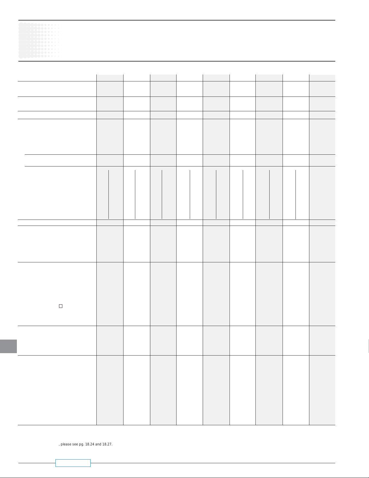
Catalog number 3 pole OT16E3 OT25E3 OT32E3 OT45E3 OT63E3 OT30E3 OT60E3 OT100E3 OT160E3
Approvals1 2 pole N/A N/A N/A N/A N/A N/A N/A N/A UL98 & IEC
3 pole UL508 & IEC UL508 & IEC UL508 & IEC UL508 & IEC UL508 & IEC UL98 & IEC UL98 & IEC UL98 & IEC UL98 & IEC
4 pole UL508 & IEC UL508 & IEC UL508 & IEC UL508 & IEC UL508 & IEC UL98 & IEC UL98 & IEC UL98 & IEC UL98 & IEC
General purpose amp rating -40° to 40°C
pf = 0.7 – 0.8 A 16 25 40 60 80 30 60 100 125
Max. operating voltage V 600 600 600 600 600 600 600 600 600
Max. horsepower rating/motor FLA current,
pf = 0.4 – 0.5
Three phase 200V – 208V HP/A 3/10.6 7.5/24.2 10/30.8 15/46.2 20/60.0 10/30.8 20/60.0 25/75.0 30/88.0
240V HP/A 5/15.2 7.5/22.0 10/28.0 15/42.0 20/54.0 10/28.0 20/54.0 30/80.0 40/104.0
480V HP/A 10/14.0 15/21.0 20/27.0 30/40.0 40/52.0 20/27.0 40/52.0 50/65.0 75/96.0
600V HP/A 10/11.0 20/22.0 25/27.0 30/32.0 40/41.0 30/32.0 40/41.0 50/52.0 100/99.0
Single phase 120V HP/A 1/16 1.5/20 2/24 2/24.0 2/24.0 2/24.0 3/34.0 5/56.0 7.5/80
240V HP/A 2/13.2 3/18.7 5/30.8 7.5/40.0 10/57.5 5/28.0 7.5/40.0 15/68.0 20/88.0
Short circuit rating with fuse
Fuse type CC kA 10 — 10 —- 10 —- — — — — — — — — — — —
Fuse type J kA 10 10 10 10 10 10 100 — 100 — 50 — 50 — 50 — 100
Fuse type T kA 10 10 10 10 10 10 100 — 100 — 50 — 50 — 50 — —
Fuse type RK1 kA 10 — 10 — 10 — — — — — — — — — — — —
Fuse type RK5 kA 5 5 5 5 5 5 10 5 10 5 — — — — — — —
Fuse type L kA — — — — — — — — — — — — — — — — —
Fuse type H kA — — — — — — — 5 — 5 — — — — — — —
Maximum fuse size A 30 60 4 30 60 4 30 60 4 100 150 100 150 60 — 150 — 150 — 200
3 cycle short circuit current withstand rating 5
Endurances
Min. Electrical endurance,
pf = 0.75 – 0.80
Min. Electrical endurance,
pf = 0.40 – 0.50 operation cycles 1000 1000 1000 1000 1000
Mechanical endurance
operations 20,000 20,000 20,000 20,000 20,000 20,000 20,000 20,000 16,000
Physical characteristics
Weight, switches 3 pole lb 0.24 0.24 0.24 0.59 0.59 0.79 0.79 0.79 2.42
4 pole lb 0.33 0.33 0.33 0.77 0.77 1.10 1.10 1.10 2.86
Dimension, switches 3 pole H in 2.68 2.68 2.68 3.60 3.60 3.94 3.94 3.94 5.00
W in 1.38 1.38 1.38 2.07 2.07 2.76 2.76 2.76 4.96
D in 2.20 2.20 2.20 2.85 2.85 2.95 2.95 2.95 2.93
Shaft set screw tightening torque lb. in. 8.9 8.9 8.9 8.9 8.9 8.9 8.9 8.9 8.9
Shaft size — square
mm 5 x 5 5 x 5 5 x 5 5 x 5 5 x 5 5 x 5 5 x 5 5 x 5 6 x 6
Switch operating torque for lb. in. 8.8 8.8 8.8 10.5 10.5 17.5 17.5 17.5 52.5
rotary 3 pole switches
Terminal lug kits
Wire range AWG #18 – 8 #18 – 8 #18 – 8 #14 – 1 #14 – 1 #14 – 4 #14 – 4 #8 – 1/0 #8 – 1/0
Torque:
Wire tightening lb. in. 7 7 7 18 18 55 55 55 70
18
Lug mounting lb. in. Integral Integral Integral Integral Integral Integral Integral Integral Integral
Auxiliary contacts OA1G_ _ OA1G_ _ OA1G_ _ OA1G_ _ OA1G_ _ OA1G_ _ OA1G_ _ OA1G_ _ OBEA_ _
NEMA ratings,
AC rated voltage VAC 600 600 600 600 600 600 600 600 600
AC thermal rated current A 10 10 10 10 10 10 10 10 10
AC maximum volt-ampere making VA 7200 7200 7200 7200 7200 7200 7200 7200 7200
AC maximum volt-ampere breaking VA 720 720 720 720 720 720 720 720 720
NEMA ratings, DC R300 R300 R300 R300 R300 R300 R300 R300 P600
DC rated voltage VDC 300 300 300 300 300 300 300 300 600
DC thermal rated current A 1 1 1 1 1 1 1 1 5
DC maximum make-break VA 28 28 28 28 28 28 28 28 138
Torque: Wire tightening lb. in 7 7 7 7 7 7 7 7 7
Wire range AWG #18 – 14 #18 – 14 #18 – 14 #18 – 14 #18 – 14 #18 – 14 #18 – 14 #18 – 14 #22 – 14
AC A600 A600 A600 A600 A600 A600 A600 A600 A600
operation cycles 6000 6000 6000 6000 6000 6000 6000 6000 6000
in .20 x .20 .20 x .20 .20 x .20 .20 x .20 .20 x .20 .20 x .20 .20 x .20 .20 x .20 .24 x .24
OT16E3 – OT160E3
UL & CSA
UL & CSA
kA — — — — — — — — 25
2 2 2 2
Not required Not required Not required Not required Not required Not required Not required Not required Not required
1 UL Listed switches are also CSA Approved.
2 UL98 overload test, 50 operations, pf 0.40 – 0.50 at 2x FLA.
3 Multi-tap lug available, please see pg. 18.24 and 18.27.
4 Fuse size 70A for RK5
5 When protected by any Listed fuse or Listed circuit breaker whose current rating does not exceed the maximum thermal current rating of the switch.
1/9/07 Revised
Technical data
Disconnect
switches
18
Non-fusible
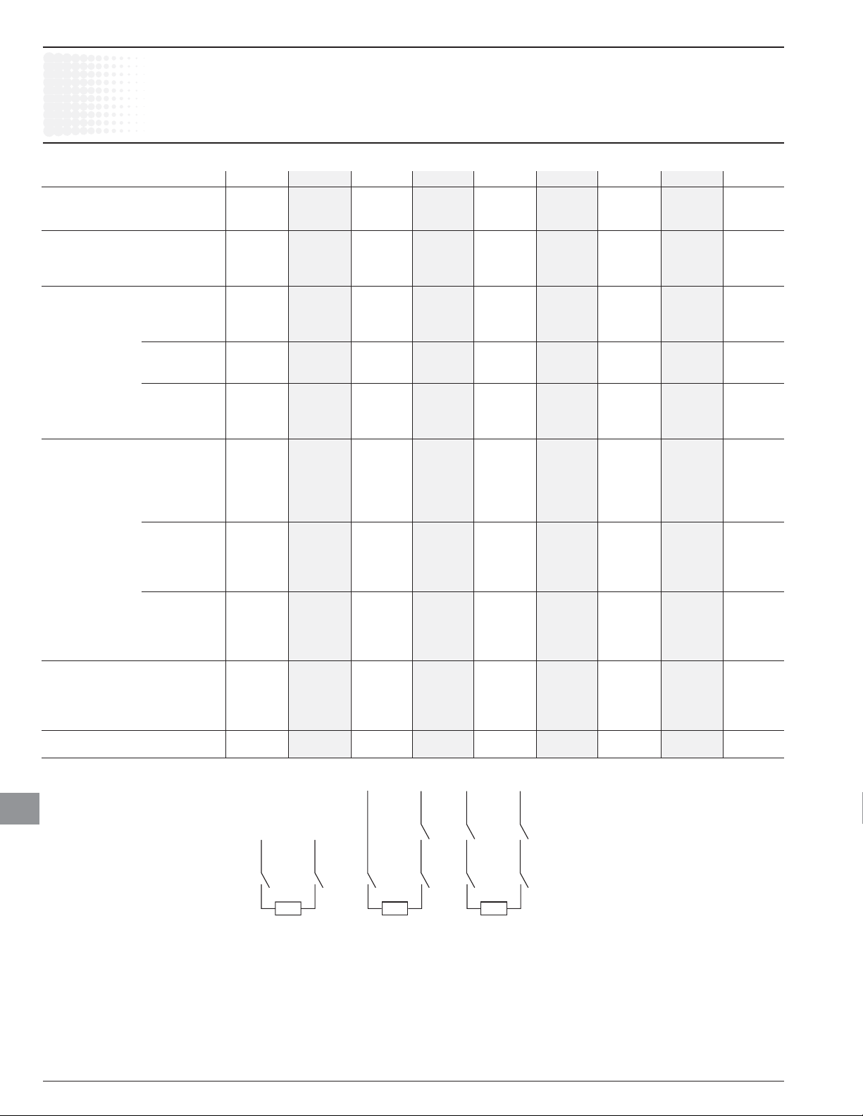
Catalog number 3 pole OT16E3 OT25E3 OT32E3 OT45E3 OT63E3 OT30E3 OT60E3 OT100E3 OT160E3
Rated insulation and operation 40°C
voltage, AC20 and DC20 V 750 750 750 750 750 750 750 750 750
Rated impulse withstand voltage kV 8 8 8 8 8 8 8 8 12
Rated thermal current, I
AC 20/DC 20 open 1 A 25 32 40 63 80 40 63 115 200
40°C enclosed A 25 32 40 63 80 40 63 115 160
60°C enclosed A 25 32 40 63 80 40 63 115 160
Rated operational currents
AC 21A ≤500V A
≤690V A 16 25 40 63 80 40 63 100 160
≤1000V A — — — — — — — — —
AC 22A ≤500V A 16 25 40 63 80 40 63 100 160
≤690V A 16 25 40 63 80 40 63 100 160
≤1000V A — — — — — — — — —
AC 23A ≤415V A 16 20 23 45 75 40 63 80 135
≤500V A 16 20 23 45 58 40 60 60 125
≤690V A 10 11 12 20 20 40 40 40 80
≤1000V A — — — — — — — — —
Rated operational currents/poles in series
DC21A 48V A 16/1
110V A 16/2
220V A 16/3
440V A 16/4 25/6 32/6
750V A 16/8 25/8 32/8
DC22A 48V A 16/1
110V A 16/2
220V A 16/3
440V A 16/6 25/8
750V A 16/8 25/8
DC23A 48V A 16/1
110V A 16/2
220V A 16/4
440V A 10/4
750V A 16/8
Rated operational power
AC23A 230V kW 3 4 5.5 11 22 7.5 11 22 45
400/415V kW 7.5 9 11 22 37 15 18.5 37 75
500V kW 7.5 9 11 22 37 15 18.5 37 75
690V kW 7.5 9 11 15 18.5 15 15 37 75
Short-circuit current kA 50 50 50 50 50 50 50 50 100
with back-up fuses of size A 25 32 40 63 80 100 100 100 200
th
OT16E3 – OT160E3
IEC
IEC
16 25 40 63 80 40 63 100 160
25/1 32/1 45/1 63/1 40/1 63/1 100/1 160/1
25/2 32/2 45/2 63/2 40/2 63/2 100/2 160/1
25/3 32/3 45/4 63/4 40/4 63/4 100/4 160/2
3 3 3 3 3 160/3
3 3 3 3 3 160/4
25/1 32/1 45/1 63/1 40/1 63/1 100/1 160/1
25/2 32/2 45/2 63/2 40/2 63/2 100/2 160/1
25/3 32/4 45/4 63/4 40/4 63/4 63/4 160/2
3 3 3 3 3 3 160/3
3 3 3 3 3 3 3
25/1 32/1 45/1 63/1 40/1 63/1 100/1 160/1
25/2 32/2 45/2 63/2 40/2 63/2 100/2 160/1
25/4 32/4 45/4 63/4 40/4 63/4 63/4 160/2
3 3 3 3 3 3 3 160/3
3 3 3 3 3 3 3 3
18
Load
2 poles
in series
1 The ambient air temperature does not exceed +40°C and its average over a
period of 24 hours does not exceed +35°C according to IEC 947.
2 IEC 947-3, utilization category B, infrequent operation.
3 Not available at time of printing, please consult factory.
Load Load
3 poles
in series
4 poles
in series
 Loading...