

Page 1
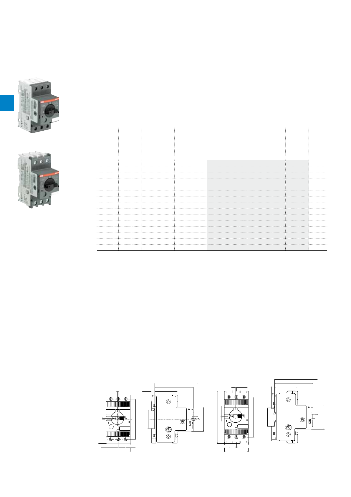
MO132 manual motor starters magnetic only
3.2"
81.25
3.19"
81.05
0.10 to 32 A – with electromagnetic protection
Description
Manual motor starters magnetic only are electromechanical protection devices for the main circuit. They are
used mainly to switch motors manually ON/OFF and protect them fuse less against short-circuit.
Fuse less protection with a manual motor starter saves costs, space and ensures a quick reaction under
2
2CDC241009F0011
MO132-6.3
2CDC241008F0011
MO132-32
short-circuit condition, by switching off the motor within milliseconds. Fuse less starter combinations are setup
together with contactors and overload relays.
Ordering details
Rated
operational
power
400 V
AC-3
kW A kA A kg
0.03 0.16 100 1.56 MO132-0.16 1SAM360000R1001 0.215
0.06 0.25 100 2.44 MO132-0.25 1SAM360000R1002 0.215
0.09 0.40 100 3.90 MO132-0.4 1SAM360000R1003 0.215
0.12 0.63 100 6.14 MO132-0.63 1SAM360000R1004 0.215
0.25 1.0 100 11.50 MO132-1.0 1SAM360000R1005 0.215
0.55 1.6 100 18.40 MO132-1.6 1SAM360000R1006 0.265
0.75 2.5 100 28.75 MO132-2.5 1SAM360000R1007 0.265
1.5 4.0 50 50.00 MO132-4.0 1SAM360000R1008 0.265
2.2 6.3 50 78.75 MO132-6.3 1SAM360000R1009 0.265
4.0 10 50 125.00 MO132-10 1SAM360000R1010 0.265
5.5 12 50 150.00 MO132-12 1SAM360000R1012 0.310
7.5 16 50 200.00 MO132-16 1SAM360000R1011 0.310
9.0 20 50 250.00 MO132-20 1SAM360000R1013 0.310
12.5 25 50 312.50 MO132-25 1SAM360000R1014 0.310
15.5 32 25 400.00 MO132-32 1SAM360000R1015 0.310
1)
For overload protection of motors, an appropriate thermal or electronic overload relay must be used
1)
Rated
operational
current
Short-circuit
breaking
capacity ICS at
400 V AC
Rated instantaneous shortcircuit current
setting l
i
Type Order code Weight
(1 pce)
2/26 | ABB
Main dimensions mm, inches
72.4
5.5
0.55"
2.95"
75
0.22"
1.38"
35
1.5
0.06"
0.1"
1.7
3.54"
90
14
0.55"
14
45
1.77"
MO132 ≤ 10 A MO132 ≥ 12 A
2.85"
43.5
1.71"
1.77"
45"
0.1"
1.7
3.85"
97.8
0.55" 0.55"
14 14
2CDC242005F0011
0.06"
1.5
1.77"
45
5.5
2.95"
1.38"
35
75
1.77"
45
2CDC242006F0011
2CDC131036C0201
2.84"
72.2
0.22"
43.3
0.22"
Page 2
MO132 manual motor starters magnetic only
Technical data
Main circuit – Utilization characteristics according to IEC/EN
Type MO132
Standards
Rated operational voltage U
Rated frequency
e
Number of poles
Duty time
Mechanical durability
Electrical durability
Rated impulse withstand voltage U
Rated insulation voltage U
Rated operational current I
Rated instantaneous short-circuit current setting I
Rated service short-circuit breaking capacity I
Rated ultimate short-circuit breaking capacity I
imp
i
e
i
cs
cu
Short-circuit breaking capacity and back-up fuses
lCSRated service short-circuit breaking capacity
Rated ultimate short-circuit breaking capacity
l
CU
ICCProspective short-circuit current at installation location
kA
> I
CC
CS
CS
I
kA
CU
Note: Maximum rated current of the back-up fuses if I
Type 230 V AC 400 V AC 440 V AC 500 V AC 690 V AC
I
kA
I
CS
kA
CU
gG, aMAI
MO132-0.16
MO132-0.25
MO132-0.4
MO132-0.63
No back-up fuse required up to ICC = 100 kA
MO132-1.0
MO132-1.6
MO132-2.5
MO132-4.0
MO132-6.3
MO132-10
MO132-12
MO132-16
MO132-20
MO132-25
MO132-32
MO132-20: No need for back-up fuse in networks with a prospective current of up to 100 kA at 400 V.
MO132-32: No need for back-up fuse in networks with a prospective current of up to 50 kA at 400 V.
With an approbiate 125 A type gG fuse the device can be used in a network with a prospective current of up to 100 kA.
50 50 125 50 50 125 10 10 125 10 10 125 3 3 100
25 50 125 25 50 125 10 10 125 10 10 125 3 3 100
IEC/EN 60947–2, IEC/EN 60947-4-1, IEC/EN 60947-1
690 V AC
50/60 Hz
3
100 %
100000 operations
50000 operations
6 kV
690 V AC
See ordering details
See ordering details
See table "Short-circuit breaking capacity and back-up fuses"
See table "Short-circuit breaking capacity and back-up fuses"
gG, aMAI
kA
I
CS
kA
CU
gG, aMAI
kA
I
CS
kA
CU
20 20 35 20 20 35 3 3 32
20 20 63 20 20 63 3 3 50
20 20 100 20 20 100 3 3 50
20 20 100 20 20 100 3 3 63
20 20 125 20 20 125 3 3 63
20 20 125 20 20 125 3 3 80
gG, aMAI
kA
CS
I
kA
2
CU
gG, aM
A
ABB | 2/27
2CDC131036C0201
Page 3
MO132 manual motor starters magnetic only
Technical data
General technical data
Type MO132
Pollution degree
Phase loss sensitivity
2
Disconnect function acc. to IEC/EN 60947-2
Ambient air temperature
Operation Open
Enclosed (IB132)
Storage
Ambient air temperature compensation
Maximum operating altitude permissible
Resistance to shock acc. to IEC 60068-2-27
Resistance to vibrations acc. to IEC 60068-2-6
Mounting position
Mounting
Group mounting
Minimum distance to other
units same type
Minimum distance to
electrical conductive board
Degree of protection
Horizontal
Vertical
Horizontal, up to 400 V
Horizontal, up to 690 V
Vertical
Housing
Main circuit terminals
3
No
Yes
-25 ... +60 °C
0 ... +40 °C
-50 ... +80 °C
2000 m
25 g / 11 ms
5 g / 3 ... 150 Hz
Position 1-6 (optional for single mounting)
DIN-rail (EN 60715)
On request
0 mm
150 mm
0 mm
> 1.5 mm
75 mm
IP20
IP20
Connecting characteristics
Main circuit
Type MO132-0.16 … MO132-10 MO132-12 … MO132-16 MO132-20 … MO132-32
Connecting capacity
Solid
Flexible
Stranded acc. to UL/CSA
Flexible acc. to UL/CSA
Stripping length
Tightening torques
Connection screw
1 or 2 x
1 ... 4 mm² 1 ... 4 mm² 2.5 ... 6 mm²
1 or 2 x
0.75 ... 2.5 mm² 0.75 ... 2.5 mm² 1 ... 6 mm²
1 or 2 x
AWG 16-12 AWG 16-12 AWG 12-8
1 or 2 x
AWG 16-12 AWG 16-12 AWG 12-8
9 mm 10 mm 10 mm
0.8 ... 1.2 Nm / 10 … 12 Ib.in 1.5 Nm / 14 Ib.in 2.0 Nm / 18 Ib.in
M3.5 (Pozidriv 2) M4 (Pozidriv 2) M4 (Pozidriv 2)
2/28 | ABB
2CDC131036C0201
Page 4
MO132 manual motor starters magnetic only
Technical data
General technical data UL/CSA
Main circuit
Maximum operational voltage
Manual motor controller ratings
Motor ratings
Electrical connection
Connecting capacity
Stripping length
Tightening torque
Connection screw
Horse power
Full load amps (FLA)
Locked rotor amps (LRA)
Stranded
Flexible without ferrule
600 V
see table “Manual motor controller for motor disconnect”
see table below
see table below
see table below
MO132 ≤ 10 A MO132-12, -16 MO132-20, -25, -32
1/2 x AWG 16 ... 12 1/2 x AWG 12 ... 8
1/2 x AWG 16 ... 12 1/2 x AWG 12 ... 8
9 mm 10 mm 10 mm
10 ... 12 lb-in 14 lb-in 18 lb-In
M3.5 (Pozidriv 2) M4 (Pozidriv 2) M4 (Pozidriv 2)
2
Motor rating, single phase
hp Horse power
FLA Full load amps
LRA Locked rotor amps
Type 220 ... 240 V AC 440 ... 480 V AC
hp FLA LRA hp FLA LRA
MO132-0.16
MO132-0.25
MO132-0.4
MO132-0.63
MO132-1.0
MO132-1.6
MO132-2.5
MO132-4.0
MO132-6.3
MO132-10
MO132-12
MO132-16
MO132-20
MO132-25
MO132-32
- 0.16 0.96 - 0.16 0.96
- 0.25 1.5 - 0.25 1.5
- 0.4 2.4 - 0.4 2.4
- 0.63 3.78 - 0.63 3.78
- 1 6 - 1 6
1/10 1.6 9.6 - 1.6 9.6
1/6 2.5 15 1/2 2.5 15
1/3 4 24 1/2 4 24
1/2 6.3 37.8 1 6.3 37.8
1-1/2 10 60 3 8.5 46
2 12 72 3 8.5 64
2 12 72 5 14 81
3 17 92 5 14 81
3 17 127 7-1/2 21 116
5 28 162 10 26 145
ABB | 2/29
2CDC131036C0201
Page 5

MO132 manual motor starters magnetic only
Technical data
Motor rating, three phase
hp Horse power
FLA Full load amps
2
LRA Locked rotor amps
Type 110 ... 120 V AC 220 ... 240 V AC 440 ... 480 V AC 500 ... 600 V AC
hp FLA LRA hp FLA LRA hp FLA LRA hp FLA LRA
MO132-0.16
MO132-0.25
MO132-0.4
MO132-0.63
MO132-1.0
MO132-1.6
MO132-2.5
MO132-4.0
MO132-6.3
MO132-10
MO132-12
MO132-16
MO132-20
MO132-25
MO132-32
- 0.16 0.96 - 0.16 0.96 - 0.16 0.96 - 0.16 0.96
- 0.25 1.5 - 0.25 1.5 - 0.25 1.5 - 0.25 1.5
- 0.4 2.4 - 0.4 2.4 - 0.4 2.4 - 0.4 2.4
- 0.63 3.78 - 0.63 3.78 - 0.63 3.78 - 0.63 3.78
- 1 6 - 1 6 - 1 6 1/2 1 6
- 1.6 9.6 - 1.6 9.6 3/4 1.6 9.6 3/4 1.6 9.6
- 2.5 15 1/2 2.5 15 1 2.5 15 1-1/2 2.5 15
- 4 24 1 4 24 2 4 2 4 3 3.9 26
1/2 6.3 37.8 1-1/2 6.3 37.8 3 4.8 32 5 6.1 37
3/4 10 60 3 9.6 64 5 7.6 46 7-1/2 9 51
1-1/2 12 72 3 9.6 64 7-1/2 11 64 10 11 65
2 16 84 5 15.2 92 10 14 81 10 11 65
3 19.2 128 5 15.2 9 2 10 14 81 15 17 93
3 19.2 128 7-1/2 22 127 15 21 116 20 22 116
5 30.4 184 10 28 162 2 0 27 145 25 27 146
Manual motor controller for motor disconnect
Type Circuit breaker or class R fuse per UL/NEC
MO132-0.16
MO132-0.25
MO132-0.4
MO132-0.63
MO132-1.0
MO132-1.6
MO132-2.5
MO132-4.0
MO132-6.3
MO132-10
MO132-12
MO132-16
MO132-20
MO132-25
MO132-32
480V / 600 V
with minimum interrupting rating of
35,000rms symmetrical amperes
Maximum short-circuit current rating
480 V 600 V
kA kA
30 18
30 18
30 18
30 18
30 18
30 18
30 18
30 18
30 18
30 18
30 18
30 18
30 18
30 18
30 18
2/30 | ABB
2CDC131036C0201
Page 6

MO132 manual motor starters magnetic only
Main accessories
Description
Three-phase busbars ensure a quick and safe connection and are therefore a cost effective solution.
Avariety of different three-phase busbars up to 100 A are in the assortment. Between 2 and 5 manual
2CDC241017F0010
PS1-2-0-65
PS1-3-1-100
1SBC101226F00141SBC101266F0014
S1-M1-25
S1-M2-25
motor starters with none, one or two lateral auxiliary contacts can be connected. Different three-phase
feeder terminals are available according to the application.
Ordering details
Rated operational
current
A kg
Three-phase busbars
2CDC241014F0010
65 2 0 PS1-2-0-65 1SAM201906R1102 10 0.034
65 3 0 PS1-3-0-65 1SAM201906R1103 10 0.055
65 4 0 PS1-4-0-65 1SAM201906R1104 10 0.077
65 5 0 PS1-5-0-65 1SAM201906R1105 10 0.098
65 2 1 PS1-2-1-65 1SAM201906R1112 10 0.036
65 3 1 PS1-3-1-65 1SAM201906R1113 10 0.060
65 4 1 PS1-4-1-65 1SAM201906R1114 10 0.087
65 5 1 PS1-5-1-65 1SAM201906R1115 10 0.108
65 2 2 PS1-2-2-65 1SAM201906R1122 10 0.040
65 3 2 PS1-3-2-65 1SAM201906R1123 10 0.067
65 4 2 PS1-4-2-65 1SAM201906R1124 10 0.095
65 5 2 PS1-5-2-65 1SAM201906R1125 10 0.122
100 3 0 PS1-3-0-100 1SAM201916R1103 10 0.084
100 4 0 PS1-4-0-100 1SAM201916R1104 10 0.117
100 5 0 PS1-5-0-100 1SAM201916R1105 10 0.154
100 3 1 PS1-3-1-100 1SAM201916R1113 10 0.094
100 4 1 PS1-4-1-100 1SAM201916R1114 10 0.134
100 5 1 PS1-5-1-100 1SAM201916R1115 10 0.172
100 3 2 PS1-3-2-100 1SAM201916R1123 10 0.105
Number of MMS Number of lateral
aux.
Type Order code Pkg
qty
2
Weight
(1 pce)
SA1
SK0108B91
Rated operational
current
A mm² kg
Three-phase feeder terminals
65 25 Flat S1-M1-25 1SAM201907R1101 10 0.038
65 25 High S1-M2-25 1SAM201907R1102 10 0.051
65 25 UL type E and IEC S1-M3-25 1SAM201907R1103 10 0.042
100 35 UL type E and IEC S1-M3-35 1SAM201913R1103 10 0.060
Description Type Order code Pkg
Protection cover for busbars BS1-3 1SAM201908R1001 50 0.003
Padlock + two keys SA2 GJF1101903R0002 10 0.020
Screw fixing kit FS116 1SAM201909R1001 1 0.020
Rated cross
section
Mounting form Type Order code Pkg
qty
qty
Weight
(1 pce)
Weight
(1 pce)
kg
ABB | 2/31
2CDC131036C0201
Page 7

MO132 manual motor starters magnetic only
Main accessories
Description
MO132 manual motor starters can be equipped with auxiliary contacts for lateral/front mounting, signalling
contact for lateral mounting, undervoltage release and shunt trips. The accessories can be fitted wiring
free and without tools. A variety of combinations is possible as required for the application. The auxiliary
1SBC101208F0014
2
HKF1-11
1SBC101209F0014
HK1-11
contacts change position with the main contacts. Undervoltage release are used for remote tripping of the
manual motor starter especially for emergency stop circuits. Shunt trips release the MMS used for remote
tripping.
Ordering details
Auxiliary
Auxiliary
contacts
N.O.
Auxiliary contacts – mountable on the front
1 1 HKF1-11 1SAM201901R1001 10 0.015
2 0 HKF1-20 1SAM201901R1002 10 0.015
Auxiliary contacts – mountable on the right
1 1 Max. 2 pieces HK1-11 1SAM201902R1001 2 0.035
2 0 Max. 2 pieces HK1-20 1SAM201902R1002 2 0.035
0 2 Max. 2 pieces HK1-02 1SAM201902R1003 2 0.035
2 0 With lead contacts HK1-20L 1SAM201902R1004 2 0.035
Signalling contacts – mountable on the right
1 1 For tripped alarm, max. 2 pieces SK1-11 1SAM201903R1001 2 0.035
2 0 For tripped alarm, max. 2 pieces SK1-20 1SAM201903R1002 2 0.035
0 2 For tripped alarm, max. 2 pieces SK1-02 1SAM201903R1003 2 0.035
Description Type Order code Pkg
contacts
N.C.
qty
Weight
(1 pce)
kg
SK1-11
AA1-24
UA1-24
1SBC101210F0014
1SBC101211F0014
1SBC101212F0014
Rated control supply
voltage
Frequency Type Order code Pkg
qty
Weight
(1 pce)
V Hz kg
Shunt trip units – mountable on the left
20 ... 24 50/60 AA1-24 1SAM201910R1001 1 0.100
110 50/60 AA1-110 1SAM201910R1002 1 0.100
200 ... 240 50/60 AA1-230 1SAM201910R1003 1 0.100
350 ... 415 50/60 AA1-400 1SAM201910R1004 1 0.100
Undervoltage releases – mountable on the left
24 50 UA1-24 1SAM201904R1001 1 0.100
48 50 UA1-48 1SAM201904R1002 1 0.100
60 50 UA1-60 1SAM201904R1003 1 0.100
110 ... 120 50/60 UA1-110 1SAM201904R1004 1 0.100
208 60 UA1-208 1SAM201904R1008 1 0.100
230 ... 240 50/60 UA1-230 1SAM201904R1005 1 0.100
400 50 UA1-400 1SAM201904R1006 1 0.100
415 ... 480 50/60 UA1-415 1SAM201904R1007 1 0.100
Main dimensions mm, inches
2.83"
3.54"
1.66"
42.1
1.77"
45
3.54"
72
90
1.77"
90
45
1.46"
37
2/32 | ABB
5.5
9
0.35"
0.22"
27.8
42.3
1.09"
1.67"
68.8
2.71"
2CDC242001F0012
HK1 UA1
1.71"
70
2.76"
5.5 43.5
0.22"
18
0.71"
2CDC242002F0012
2CDC131036C0201
Page 8

MO132 manual motor starters magnetic only
S1-M2-25
Main accessories
Manual motor starter with three-phase busbar systems
S1-M3-35
PS1-..-65
S1-M1-25
BS1-3
PS1-..-65
MO132
MO132
PS1-..-100
MO132
2
MO132
Three-phase busbar up to 65 A Three-phase busbar up to 100 A
2CDC242019F0011
General technical data
Type PS1-xxx-65 PS1-xxx-100 S1-Mx-25 S1-Mx-35
Standards
Rated operational voltage U
Rated operational current I
Rated frequency
Rated impulse withstand voltage U
Rated insulation voltage U
Pollution degree
Cross-section
Ambient air temperature
Resistance to shock acc. to IEC 60068-2-27
Resistance to vibrations acc. to IEC 60068-2-6
e
e
imp
i
Operation
Storage
IEC/EN 60947-4-1, IEC/EN 60947-1
690 V
65 A 100 A 65 A 100 A
50/60 Hz
6 kV
690 V AC
3
10 mm² 16 mm² 25 mm² 35 mm²
-25 ... +70 °C
-50 ... +80 °C
25 g / 11 ms
5 g / 3 ... 150 Hz
Electrical connection
Main circuit
Type S1-Mx-25 S1-Mx-35
Connecting capacity
Solid
Flexible
Stranded acc. to UL/CSA
Flexible acc. to UL/CSA
Stripping length
Tightening torques
Connection screw
1 x
6 ... 25 mm² 10 ... 35 mm²
1 x
6 ... 16 mm² 10 ... 35 mm²
1 x
AWG 10-4 AWG 8-2
1 x
AWG 10-6 AWG 8-2
10 mm 12 mm
2.5 Nm / 22 Ib.in 4.5 Nm / 40 Ib.in
PZ2 (6 mm) Hexagon SW4
2CDC242020F0011
ABB | 2/33
2CDC131036C0201
Page 9

MO132 manual motor starters magnetic only
Main accessories
Manual motor starter with accessories
2
SK1
HK1
MS116
MO132
HK1
AA1
HKF1
UA1
HK1
2CDC246001F0013
General technical data
Type HK1 SK1 HKF1
Standards
Rated operational voltage U
Conventional free-air thermal current I
Rated frequency
Rated impulse withstand voltage U
Rated insulation voltage U
Pollution degree
Ambient air temperature
Resistance to shock acc. to IEC 60068-2-27
Resistance to vibrations acc. to IEC 60068-2-6
Ie / Rated operational current AC-15
acc. to IEC/EN 60947-5-1 for utilization category
Ie / Rated operational current DC-13
acc. to IEC/EN 60947-5-1 for utilization category
Minimum switching capacity
Short-circuit protective device
Duty time
Mounting
Mounting positions
Mechanical durability
Electrical durability
e
th
imp
i
Operation
Storage
24 V, 120 V
440 V, 690 V
440 V, 600 V
N.C., 95-96
N.O., 97-98
IEC/EN 60947-2, IEC/EN 60947-4-1, IEC/EN 60947-1
690 V AC / 600 DC 250 V AC / 250 V DC
6 A 5 A
50/60 Hz
6 kV
690 V AC 250 V AC
3
-25 ... +70 °C
-50 ... +80 °C
25 g / 11 ms
5 g / 3 ... 150 Hz
6 A 3 A
240 V
4 A 1.5 A
400 V
3 A -
1 A -
24 V
2 A 1 A
125 V
0.55 A 0.27 A
250 V
0.27 A 0.11 A
0.15 A -
17 V / 5 mA
10 A Type gG
10 A Type gG
100 %
Right side of MMS Front of MMS
1-6
50000 cycles -
50000 cycles -
2/34 | ABB
2CDC131036C0201
Page 10

MO132 manual motor starters magnetic only
Main accessories
Electrical connection
Main circuit
Type HK1 SK1 HKF1
Connecting capacity
Solid
Flexible
Stranded acc. to UL/CSA
Flexible acc. to UL/CSA
Stripping length
Tightening torques
Connection screw
1 or 2 x
1 ... 1.5 mm² 1 ... 2.5 mm²
1 or 2 x
0.75 ... 1.5 mm²
1 or 2 x
AWG 16-14
1 or 2 x
AWG 16-14
8 mm
0.8 ... 1.2 Nm / 7 Ib.in
M3 (Pozidriv 2)
2
ABB | 2/35
2CDC131036C0201
Page 11

119 4.69"
183 7.2"
118 4.65"
121 4.76"
135.7 5.34"
92 3.62" 24 .94"
MO132 manual motor starters magnetic only
Main accessories
Description
IB132 are IP65 enclosures for single MMS installation. Additional mounting of auxiliary and signalling
contacts, shunt trips and undervoltage release is possible. The handle is lockable in OFF position. For
detailed specification see installation instruction.
2
2CDC241004F0010
IB132-Y
2CDC241003F0010
IB132-G
DMS132 are IP65 door mounting kits for MMS installation in any enclosure. Additional mounting of
auxiliary, signalling, shunt trips and undervoltage release is possible. The handle is lockable in OFF
position. For detailed specification see installation instruction.
Ordering details
Description Color Type Order code
Enclosures IP65
Padlockable max. 3 padlocks with bail
diameter 4 ... 6.5 mm
Door mounting kit IP65
Padlockable max. 3 padlocks with bail
diameter 4 ... 6.5 mm
Indication I-O-T and ON-OFF-T
Yellow/red IB132-Y 1SAM201911R1011 1 0.370
Grey/black IB132-G 1SAM201911R1010 1 0.370
Yellow/red DMS132-Y 1SAM201912R1011 1 0.170
Grey/black DMS132-G 1SAM201912R1010 1 0.170
Pkg
qty
Weight
(1 pce)
kg
DMS132-Y
DMS132-G
2CDC241002F0010
2CDC241001F0010
Main dimensions mm, inches
I
ON
0
OFF
174 6.85"
194 7.64"
I
ON
0
OFF
2/36 | ABB
2CDC242011F0011
IB132 DMS132
116.15 4.57"
2CDC242012F0011
2CDC131036C0201
Page 12

MO132 manual motor starters magnetic only
Main accessories
Description
The complete set includes handle, shaft and driver. All accessories fit 6 mm shafts of maximum 180 mm
length. The degree of protection for handles MSHD is IP64.
MSHD-LTB
MSHD-LTY
MSMN
MSOX-30
2CDC241007F0011
2CDC241006F0011
2CDC241004F0011
2CDC241005F0011
Ordering details
Description Shaft length Type Order code
mm
Shafts
For selector type handles. Shaft diameter
6 mm. Shaft extension for door coupling
driver.
Description Color Type Order code
Selector type handles IP64
Padlockable max. 3 padlocks with bail
diameter 5 … 8 mm, door interlock in ON
position defeatable, for use with 6 mm
OXS6…types up to 180 mm or driver
shafts MSOX.
1)
Indication I-O-T and ON-OFF-T
Description Type Order code
Driver
Coupling driver for use with 6 mm OXS6… types up to
180 mm.
1)
Coded - Positioning of ON indication dependent from mounting orientation of the MS
2)
Uncoded - Positioning of ON indication independent from mounting orientation of the MS
85 OXS6X85 1SCA101647R1001 1 0.020
105 OXS6X105 1SCA108043R1001 1 0.020
130 OXS6X130 1SCA101655R1001 1 0.030
180 OXS6X180 1SCA101659R1001 1 0.040
mm
Black MSHD-LTB
Yellow MSHD-LTY
MSMN
MSMNO
1)
1SAM201920R1011 1 0.065
1)
1SAM201920R1012 1 0.065
1)
2)
1SAM101923R0002 1 0.002
1SAM101923R0012 1 0.002
Pkg
qty
Pkg
qty
Pkg
qty
Weight
(1 pce)
kg
Weight
(1 pce)
kg
Weight
(1 pce)
kg
2
MSH-AR
Shaft alignment ring
2CDC241001F0012
Description Shaft length Type Order code
mm
Driver shafts
Driver shaft - combination driver & shaft.
Shaft diameter 6 mm.
1)
MSOX-32 is for normal vertical use
2)
MSOX-30 is for horizontal use
Description Type Order code
2CDC242003F0012
32 MSOX-32
30 MSOX-30
1)
2)
Shaft alignment ring
The MSH-AR supports the long axis for alignment to the
MSH-AR 1SAM201920R1000 1 0.010
handle inlet. It makes closing panel doors more easy.
Pkg
Weight
qty
(1 pce)
kg
1SAM101924R0003 1 0.010
1SAM101924R0013 1 0.010
Pkg
Weight
qty
(1 pce)
kg
2CDC131036C0201
ABB | 2/37
 Loading...