

Page 1
Product manual │ 13.01.2021
ABB-free@home®
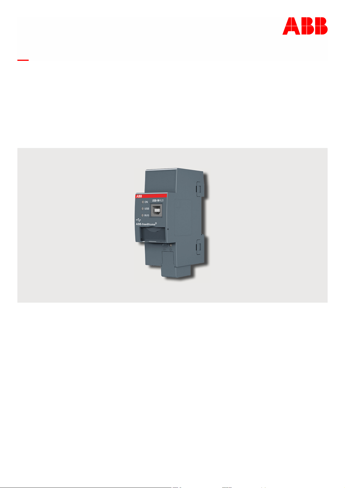
USB-M-1.1
USB-Interface, MDRC
Branding -- Release 2018-01-01
Page 2

│
Table of contents
Table of contents
1 Notes on the instruction manual .................................................................................................................... 3
2 Safety ............................................................................................................................................................. 4
2.1 Information and symbols used ........................................................................................................... 4
2.2 Intended use ...................................................................................................................................... 5
2.3 Improper use ...................................................................................................................................... 5
2.4 Target group / Qualifications of personnel ......................................................................................... 6
2.4.1
Operation ..................................................................................................................................... 7
2.4.2
Installation, commissioning and maintenance .............................................................................. 7
2.5 Safety instructions .............................................................................................................................. 8
2.6 Liability and warranty ......................................................................................................................... 8
3 Information on protection of the environment ............................................................................................... 9
3.1 Environment ....................................................................................................................................... 9
4 Setup and function ....................................................................................................................................... 10
4.1 Introduction ....................................................................................................................................... 10
4.2 Device overview ............................................................................................................................... 11
4.3 Overview of types ............................................................................................................................. 12
4.4 Scope of supply ................................................................................................................................ 13
5 Technical data ............................................................................................................................................. 14
5.1 Technical data .................................................................................................................................. 14
5.2 Dimensional drawings ...................................................................................................................... 16
6 Connection, installation / mounting ............................................................................................................. 17
6.1 Requirements for the electrician ...................................................................................................... 17
6.2 Mounting / dismantling ..................................................................................................................... 18
6.2.1
Mounting .................................................................................................................................... 18
6.3 Electrical connection ........................................................................................................................ 19
7 Commissioning ............................................................................................................................................ 20
7.1 Initial commissioning ........................................................................................................................ 20
8 Operation ..................................................................................................................................................... 21
9 Maintenance ................................................................................................................................................ 22
9.1 Maintenance-free device .................................................................................................................. 22
9.2 Cleaning ........................................................................................................................................... 22
10 Notes ............................................................................................................................................................ 23
11 Index ............................................................................................................................................................ 24
Product manual 9AKK107991A4899
2
Page 3

│
Notes on the instruction manual
1 Notes on the instruction manual
Please read through this manual carefully and observe the information it contains. This will
assist you in preventing injuries and damage to property, and ensure both reliable operation and
a long service life for the device.
Please keep this manual in a safe place.
If you pass the device on, also pass on this manual along with it.
ABB accepts no liability for any failure to observe the instructions in this manual.
If you require additional information or have questions about the device, please contact ABB or
visit our Internet site at:
www.BUSCH-JAEGER.com
Product manual 9AKK107991A4899
3
Page 4
│
2 Safety
The device has been constructed according to the latest valid regulations governing technology
and is operationally reliable. It has been tested and left the factory in a technically safe and
reliable state.
However, residual hazards remain. Read and adhere to the safety instructions to prevent
hazards of this kind.
ABB accepts no liability for any failure to observe the safety instructions.
2.1 Information and symbols used
The following Instructions point to particular hazards involved in the use of the device or provide
practical instructions:
Danger
Risk of death / serious damage to health
– The respective warning symbol in connection with the signal word "Danger"
indicates an imminently threatening danger which leads to death or serious
(irreversible) injuries.
Warning
Serious damage to health
– The respective warning symbol in connection with the signal word "Warning"
indicates a threatening danger which can lead to death or serious
(irreversible) injuries.
Caution
Damage to health
– The respective warning symbol in connection with the signal word "Caution"
indicates a danger which can lead to minor (reversible) injuries.
Attention
Damage to property
– This symbol in connection with the signal word "Attention" indicates a
situation which could cause damage to the product itself or to objects in its
surroundings.
NOTE
This symbol in connection with the word "Note" indicates useful tips and
recommendations for the efficient handling of the product.
Safety
The following safety symbols are used in the operating manual:
This symbol alerts to electric voltage.
Product manual 9AKK107991A4899
4
Page 5

│
2.2 Intended use
The device must only be operated within the specified technical data.
The USB-Interface, MDRC is suitable for installation on mounting rails according to DIN EN
60715.
The USB-Interface, MDRC makes the communication of a ABB-free@home
central Twisted Pair line possible.
2.3 Improper use
Each use not listed in Chapter 2.2 “Intended use“ on page 5 is deemed improper use and can
lead to personal injury and damage to property.
ABB is not liable for damages caused by use deemed contrary to the intended use of the
device. The associated risk is borne exclusively by the user/operator.
The device is not intended for the following:
■
Unauthorized structural changes
■
Repairs
■
Outdoor use
■
Use of available connection options contrary to technical data.
Safety
®
installation and a
Product manual 9AKK107991A4899
5
Page 6

│
2.4 Target group / Qualifications of personnel
Installation, commissioning and maintenance of the device must only be carried out by trained
and properly qualified electrical installers.
The electrical installer must have read and understood the manual and follow the instructions
provided.
The electrical installer must adhere to the valid national regulations in his/her country governing
the installation, functional test, repair and maintenance of electrical products.
Safety
Product manual 9AKK107991A4899
6
Page 7

│
2.4.1 Operation
No special qualifications are needed to operate the device.
2.4.2 Installation, commissioning and maintenance
Installation, commissioning and maintenance of the device must only be carried out by trained
and properly qualified electrical installers.
The electrical installer must have read and understood the manual and follow the instructions
provided.
The electrical installer must adhere to the valid national regulations in his/her country governing
the installation, functional test, repair and maintenance of electrical products.
The electrical installer must be familiar with and correctly apply the "five safety rules" (DIN VDE
0105, EN 50110):
1. Disconnect
2. Secure against being re-connected
3. Ensure there is no voltage
4. Connect to earth and short-circuit
5. Cover or barricade adjacent live parts
Safety
Product manual 9AKK107991A4899
7
Page 8

│
2.5 Safety instructions
Danger - Electric voltage!
Electric voltage! Risk of death and fire due to electric voltage of 100 … 240 V.
Dangerous currents flow through the body when coming into direct or indirect
contact with live components. This can result in electric shock, burns or even
death.
■
Work on the 100 … 240 V supply system may only be performed by
authorised and qualified electricians.
■
Disconnect the mains power supply before installation / disassembly.
■
Never use the device with damaged connecting cables.
■
Do not open covers firmly bolted to the housing of the device.
■
Use the device only in a technically faultless state.
■
Do not make changes to or perform repairs on the device, on its components
or its accessories.
■
Keep the device away from water and wet surroundings.
Caution! - Risk of damaging the device due to external factors!
Moisture and contamination can damage the device.
■
Protect the device against humidity, dirt and damage during transport,
storage and operation.
Safety
2.6 Liability and warranty
Improper use, non-observance of this manual, the use of inadequately qualified personnel, as
well as unauthorized modification excludes the liability of the manufacturer for the damages
caused. It voids the warranty of the manufacturer.
Product manual 9AKK107991A4899
8
Page 9

│
Information on protection of the environment
3 Information on protection of the environment
3.1 Environment
Consider the protection of the environment!
Used electric and electronic devices must not be disposed of with domestic
waste.
– The device contains valuable raw materials which can be recycled.
Therefore, dispose of the device at the appropriate collecting depot.
All packaging materials and devices bear the markings and test seals for proper disposal.
Always dispose of the packaging material and electric devices and their components via the
authorized collecting depots and disposal companies.
The products meet the legal requirements, in particular the laws governing electronic and
electrical devices and the REACH ordinance.
(EU Directive 2012/19/EU WEEE and 2011/65/EU RoHS)
(EU REACH ordinance and law for the implementation of the ordinance (EC) No.1907/2006).
Product manual 9AKK107991A4899
9
Page 10

│
4 Setup and function
4.1 Introduction
The ABB-free@home
(MDRC) for installation in the distributer on a mounting rail according to DIN EN 60715.
In applications in which a central device (e.g. a weather station) is to be made available for
several ABB-free@home
The USB interface is connected to the System Access Point via USB (Type B). All USB
interfaces in a building are then interconnected via a Twisted Pair cable.
The central line, like all individual ABB-free@home
free@home
®
power supply and a System Access Point for configuring the weather station.
The device is connected to the System Access Point via a Type B USB cable and is operational
as soon as the USB is connected. The USB-Interface, MDRC does not need to be configured,
since this takes place automatically via the System Access Point.
The operating status is displayed via 3 LEDs. The bus part and the USB part are isolated
galvanically from each other.
®
USB-Interface, MDRC USB-M-1.1 is a modular DIN-Rail Component
®
systems, this can be done by adding a central Twisted Pair line.
Setup and function
®
systems, requires its own ABB-
For example:
Fig. 1: Example of an apartment building installation
[A] Bus line
[B] USB
[C] Central line
Notice
The ABB-free@home
central line [B].
®
bus line [A] must not be connected directly with the
Product manual 9AKK107991A4899
10
Page 11

│
4.2 Device overview
Fig. 2: Overview of devices
[1] Label holder
[2] No function
[3] No function
[4] Bus connection terminal
[5] Cover cap
[6] LED ON (green)
[7] LED USB (yellow)
[8] LED bus (yellow)
[9] USB socket type B
Setup and function
Product manual 9AKK107991A4899
11
Page 12

│
4.3 Overview of types
Type Product name Product identity number
USB-M-1.1 USB-Interface, MDRC 2CDG510013R0011
Table 1: Overview of types
Setup and function
Product manual 9AKK107991A4899
12
Page 13

│
4.4 Scope of supply
The scope of supply contains the device including the bus terminal for coupling to the ABBfree@home
®
bus (central line).
Setup and function
Product manual 9AKK107991A4899
13
Page 14

│
5 Technical data
5.1 Technical data
Designation
Supply voltage
ABB-free@home
®
USB
Power consumption
ABB-free@home
®
USB
Power loss
ABB-free@home
®
USB
Total power loss
Connectors
ABB-free@home
®
USB
Control and display
elements
Green LED
Yellow LED
Yellow LED
Programming LED and
push-button
Via free@home bus (21 - 30 V DC)
5 VDC
Max. 3 mA
Max. 15 mA
Max. 100 mW
Max. 75 mW
Max. 200 mW
free@home Connecting terminal, 0.8 Ø, single wire
USB standard 1.1, type B socket, max. cable length 5 m
Display of operational readiness
Display of USB operational readiness
Display of connected free@home bus
Without function
Technical data
Protection rating IP20, according to DIN EN 60 529
Protection class III according to DIN EN 61 140
Insulation category
Overvoltage category
Pollution degree
Safety Extra Low Voltage SELV 24 V DC
III according to DIN EN 60 664-1
II according to DIN EN 60 664-1
Product manual 9AKK107991A4899
14
Page 15

│
Technical data
Designation
Temperature range
Operation
Transport
Storage
Ambient conditions
Maximum humidity
Air pressure
Design
Rail mounting device
(MDRC)
Construction type
Housing/colour
Dimensions
Dimensions
Installation width MW
- 5 to +45°C
-25 to +70 °C
-25 to +55 °C
95%, no dew permissible
Atmosphere up to 2,000 m
Modular installation device
Pro M
Plastic, grey, halogen free
90 x 36 x 63.5 mm (H x W x D)
2 modules à 18 mm
Mounting On mounting rail 35 mm according to DIN EN 60 715
Built-in position Any
Weight 0.08 kg
Fire classification Flammability V-0 acc. to UL94
CE marking According to EMC and low-voltage guidelines
Table 2: Technical data
Product manual 9AKK107991A4899
15
Page 16

│
5.2 Dimensional drawings
Fig. 3: Dimensions in mm
Technical data
Product manual 9AKK107991A4899
16
Page 17

│
Connection, installation / mounting
6 Connection, installation / mounting
6.1 Requirements for the electrician
Danger - Electric voltage!
Install the device only if you have the necessary electrical engineering
knowledge and experience.
■
Incorrect installation endangers your life and that of the user of the electrical
system.
■
Incorrect installation can cause serious damage to property, e.g. due to fire.
The minimum necessary expert knowledge and requirements for the installation
are as follows:
■
Apply the "five safety rules" (DIN VDE 0105, EN 50110):
1. Disconnect
2. Secure against being re-connected
3. Ensure there is no voltage
4. Connect to earth and short-circuit
5. Cover or barricade adjacent live parts.
■
Use suitable personal protective clothing.
■
Use only suitable tools and measuring devices.
■
Check the type of supply network (TN system, IT system, TT system) to
secure the following power supply conditions (classic connection to ground,
protective earthing, necessary additional measures, etc.).
Danger - Short-circuit in the low-voltage line
■
Risk of death due to short-circuit
■
Risk of death due to electrical voltage of 230 V during short-circuit in the lowvoltage line.
– During mounting observe the spatial division (> 10 mm) of SELV electric
circuits to other electric circuits.
– If the minimum distance is insufficient, use electronic boxes or insulating
tubes.
– Observe the correct polarity.
Product manual 9AKK107991A4899
17
Page 18

│
6.2 Mounting / dismantling
6.2.1 Mounting
Installation
To install the device, perform the following steps:
– Latch the modular DIN rail component onto the mounting rail.
Connection, installation / mounting
Fig. 4: Installation on mounting rails
Dismantling
To dismantle the device, perform the following steps:
– Press the device down [1] and then fold it toward the front [2].
Fig. 5: Removal from the mounting rails
Product manual 9AKK107991A4899
18
Page 19

│
6.3 Electrical connection
fr ee@home Bus
Fig. 6: Electrical connection
Connection, installation / mounting
5 - 6 mm
Notice
– The bus line connection is established by means of the enclosed bus
connection terminal (red/black).
– The USB connection is established by means of the Type B USB socket.
Product manual 9AKK107991A4899
19
Page 20

│
7 Commissioning
7.1 Initial commissioning
The device connected to the bus line is automatically recognized by the system after a few
seconds. Parameterisation is not required.
– All devices connected to the central line are now recognised automatically and displayed
consecutively in the Web application.
– Devices on the central line, e.g. the weather station, cannot be configured from the
individual system, but only with the System Access Point.
– It can take up to 10 minutes until all devices are displayed. This can be accelerated by
carrying out a reset for the line.
Commissioning
Product manual 9AKK107991A4899
20
Page 21

│
8 Operation
2
1
Fig. 7: Control elements
[1] LED ON (green):
– The LED lights up permanently when the USB is connected.
3
4
Operation
[2] LED USB (yellow):
– The LED lights up permanently when the USB is connected.
– The LED flashes during the USB data traffic.
[3] LED bus (yellow):
– The LED lights up permanently when the USB and the ABB-free@home
– The LED flashes during ABB-free@home
[4] USB socket type B
®
data traffic.
®
are connected.
Product manual 9AKK107991A4899
21
Page 22

│
9 Maintenance
9.1 Maintenance-free device
The device is maintenance-free. In case of damage, e.g. during transport or storage), do not
perform repairs. Once the device is opened, the warranty is void.
Access to the device must be guaranteed for operation, testing, inspection, maintenance and
repairs (according to DIN VDE 0100-520).
9.2 Cleaning
Caution! - Risk of damaging the device!
■
When spraying on cleaning agents, these can enter the device through
crevices.
– Do not spray cleaning agents directly onto the device.
■
Aggressive cleaning agents can damage the surface of the device.
– Never use caustic agents, abrasive agents or solvents.
Maintenance
Clean dirty devices with a soft dry cloth.
– If this is insufficient, the cloth can be moistened slightly with a soap solution.
Product manual 9AKK107991A4899
22
Page 23

│
10 Notes
Notes
Product manual 9AKK107991A4899
23
Page 24

│
11 Index
C
Cleaning ..................................................... 22
Commissioning ............................................. 20
Connection, installation / mounting .................... 17
D
Device overview ........................................... 11
Dimensional drawings ..................................... 16
dismantling ................................................. 18
E
Electrical connection ..................................... 19
Electrical installer ........................................... 6
Environment .................................................. 9
I
Improper use ................................................. 5
Information and symbols used ............................. 4
Information on protection of the environment ......... 9
Initial commissioning ...................................... 20
Intended use .................................................. 5
Introduction ................................................ 10
L
Liability and warranty ...................................... 8
Index
Mounting ..................................................... 18
N
Notes ......................................................... 23
Notes on the instruction manual .......................... 3
O
Operation ................................................ 7, 21
Overview of types .......................................... 12
Q
Qualification of personnel ................................. 6
R
Requirements for the electrician ........................ 17
S
Safety ......................................................... 4
Safety instructions .......................................... 8
Scope of supply ............................................. 13
Setup and function ......................................... 10
T
Target group ................................................. 6
Technical data .............................................. 14
M
Maintenance ................................................ 22
Maintenance-free device ................................. 22
Product manual 9AKK107991A4899
24
Page 25

Busch-Jaeger Elektro GmbH
A member of the ABB Group
Freisenbergstraße 2
58513 Lüdenscheid
www.BUSCH-JAEGER.com
info.bje@de.abb.com
Central sales service:
Tel.: +49 2351 956-1600
Fax: +49 2351 956-1700
Copyright© 2021 Busch-Jaeger Elektro GmbH
All rights reserved
9AKK107991A4899
 Loading...