

Page 1
VER:1.1 │ │ 10.09.2015
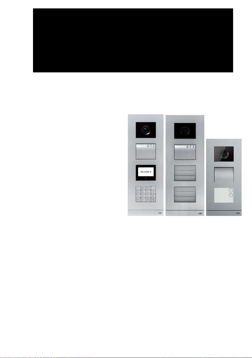
ABB-Welcome
M25102xC
M25102xA-x-
M25102xPx.
M25102xK-x.
M25102xCR.
5102xDN
5101xPx
Outdoor station
Pos: 2 /DinA4 - Anleitungen Online/Inhalt/KN X/DoorEntry/83220-AP-xxx/Titelblatt - 83220-AP-xxx - A BB @ 19\mod_1323249806476_15.docx @ 111084 @ @ 1
Page 2
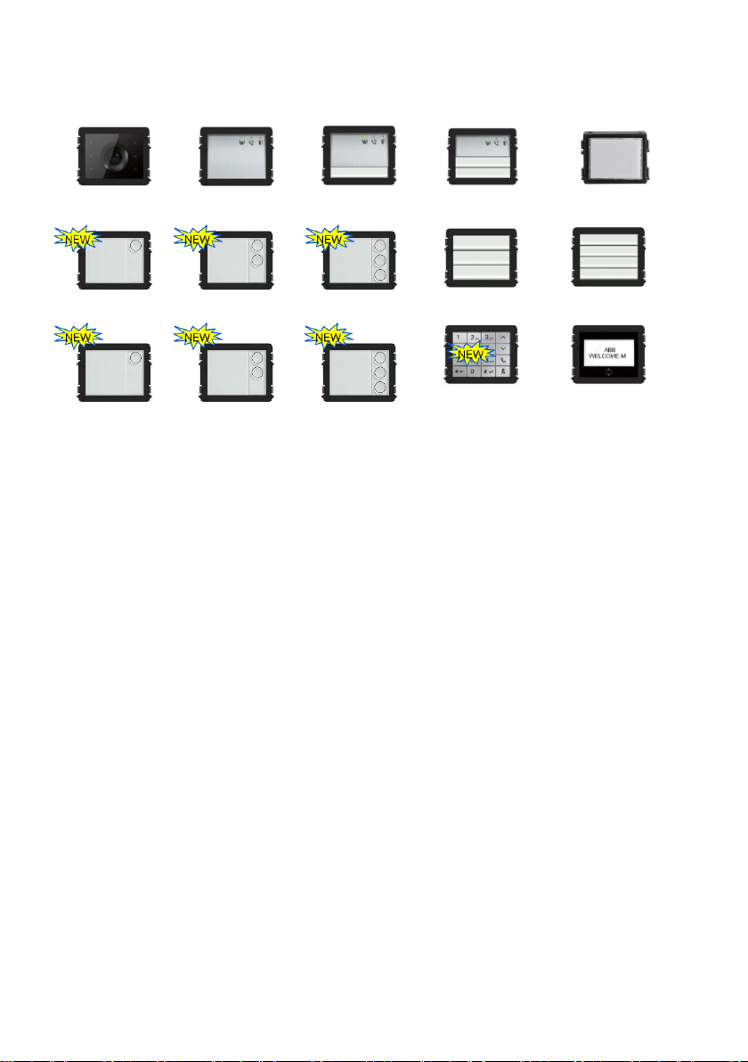
Audio module
Audio module
1/2 button
Audio module
2/4 button
Nameplate module
Round pushbutton
2 button
Camera module
Round pushbutton
1 button
Round pushbutton
3 button
Pushbutton
3/6 button
Pushbutton
4/8 button
Round pushbutton
1 button, with NFC/IC
Display with ID
Display with IC
Round pushbutton
2 button, with NFC/IC
Round pushbutton
3 button, with NFC/IC
Keypad (3 versions)
Stainless steel
Aluminum
White
Module family
=== Ende der Liste für Textmarke Cover ===
Page 3

ABB-Welcome
|
— 3 —
Pos: 4 /Busch-Jaeger (Neustruktur)/M odul-Struktur/Online-Dokumentation/Inhaltsverzeichnis (--> Für alle Do kumente <--)/Inhaltsverzeichnis @ 19\mod_1320649044386_1 5.docx @ 109653 @ @ 1
1 Safety ............................................................................................................ 5
2 Intended use .................................................................................................. 5
3 Environment .................................................................................................. 5
3.1 ABB devices ................................................................................. 5
4 Terminal description ...................................................................................... 7
4.1 Audio module ................................ ................................ ................ 7
4.1.1 Lock connected with terminals 3 and 4 ....................................... 13
4.2 Camera module .......................................................................... 14
4.2.1 Analog camera connected with terminal 1 .................................. 15
4.2.2 Detached camera connection ..................................................... 16
4.3 Round pushbutton module .......................................................... 17
4.4 Pushbutton module ..................................................................... 19
4.5 Keypad module ........................................................................... 21
4.6 Display and card reader module ................................................. 23
4.7 Nameplate module ..................................................................... 25
5 Operation ..................................................................................................... 27
5.1 Pushbutton outdoor station ......................................................... 27
5.1.1 Addressing .................................................................................. 27
5.1.2 Setting the language for the voice messages (if the audio module
has a speech synthesis function) ................................................ 31
5.2 Pushbutton outdoor station with display module ......................... 34
5.3 Pushbutton outdoor station with keypad module ........................ 36
5.4 Round pushbutton outdoor station with IC/NFC ......................... 38
5.5 Keypad outdoor station ............................................................... 42
5.5.1 Call a resident (3 types) .............................................................. 42
5.5.2 Call the guard unit ...................................................................... 44
5.5.3 If an indoor station is in “leave home mode” ............................... 44
5.5.4 If a guard unit is in "intercept mode" ........................................... 45
5.5.5 System settings .......................................................................... 46
5.6 Keypad outdoor station without display (camera + audio +
keypad) ....................................................................................... 56
5.6.1 Calling a resident by inputting physical address ......................... 56
5.6.2 Call guard unit ............................................................................ 56
5.6.3 System settings .......................................................................... 56
6 Advanced configuration ............................................................................... 58
7 Technical data ............................................................................................. 59
8 Mounting/installation .................................................................................... 60
Page 4

ABB-Welcome
|
— 4 —
8.1 Requirements for the electrician ................................................. 60
8.2 General installation instructions .................................................. 61
8.3 Mounting ..................................................................................... 62
=== Ende der Liste für Textmarke TOC ===
Page 5
ABB-Welcome
Safety
|
— 5 —
Warning
Electric voltage!
Risk of death and fire due to electrical voltage of 100-240 V.
– Work on the 100-240V supply system may only be performed by
authorized electricians!
– Disconnect the mains power supply prior to installation and/or
disassembly!
Consider the protection of the environment!
Used electric and electronic devices must not be disposed of with
household waste.
– The device contains valuable raw materials that can be recycled.
Therefore, dispose of the device at the appropriate collecting
facility.
Pos: 6 /Busch-Jaeger (Neustruktur)/M odul-Struktur/Online-Dokumentation/Überschriften (--> Für alle Dokumente <--)/1. Ebene/S - T/Sicherheit @ 18\mod_1302612791790 _15.docx @ 103357 @ 1 @ 1
1 Safety
Pos: 7 /Busch-Jaeger (Neustruktur)/M odul-Struktur/Online-Dokumentation/Sicherheit (--> Für alle Dokumente <--)/W arnhinweise/Sicherheit - 230 V @ 18\mod_1302606816 750_15.docx @ 103308 @ @ 1
Pos: 8 /Busch-Jaeger (Neustruktur)/M odul-Struktur/Online-Dokumentation/Überschriften (--> Für alle Dokumente <--)/1. Ebene/A - F/Bestimmungsgemäßer Gebrauch @ 18\mod_130276332 1316_15.docx @ 103483 @ 1 @ 1
2 Intended use
Pos: 9 /DinA4 - Anleitungen Online/Inhalt /KNX/DoorEntry/83220-AP-xxx/Bestimmungsgema esser Gebrauch - 83220-AP-xxx-500 @ 20\mod_132456116869 9_15.docx @ 112728 @ @ 1
The outdoor station is an integral part of the ABB-Welcome door entry system and
operates exclusively with components from this system. The device must only be used
with suitable ABB flush-mounted installation sockets and rain hood.
Pos: 10 /Busch-Jaeger (Neustruktur)/Mo dul-Struktur/Online-Dokumentation/Überschriften (--> Für alle Dokument e <--)/1. Ebene/U - Z/Umwelt @ 18\mod_1302614158967_1 5.docx @ 103383 @ 1 @ 1
3 Environment
Pos: 11 /Busch-Jaeger (Neustruktur)/Mo dul-Struktur/Online-Dokumentation/Umwelt (--> Für alle Dokumente <--)/Hin weise/Hinweis - Umwelt - Hinweis Elektrogeräte @ 18\mod_1302 763973434_15.docx @ 103500 @ @ 1
Pos: 12 /DinA4 - Anleitungen Online/Ueb erschriften/2./ABB Geraete @ 19\mod_1323162843832 _15.docx @ 110875 @ 2 @ 1
3.1 ABB devices
Pos: 13 /Busch-Jaeger (Neustruktur)/Mo dul-Struktur/Online-Dokumentation/Umwelt (--> Für alle Dokumente <--)/Hin weise/Hinweis - Umwelt - ABB Elektrogeräte @ 19\mod_13231627 45839_15.docx @ 110867 @ @ 1
All packaging materials and devices from ABB bear the markings and test seals for
proper disposal. Always dispose of the packing materials and electric devices and their
components via an authorized collection facility or disposal company.
Page 6

ABB-Welcome
Environment
|
— 6 —
ABB products meet the legal requirements, in particular the laws governing electronic
and electrical devices and the REACH ordinance.
(EU-Directive 2002/96/EG WEEE and 2002/95/EG RoHS)
(EU-REACH ordinance and law for the implementation of the ordinance (EG)
No.1907/2006)
Page 7
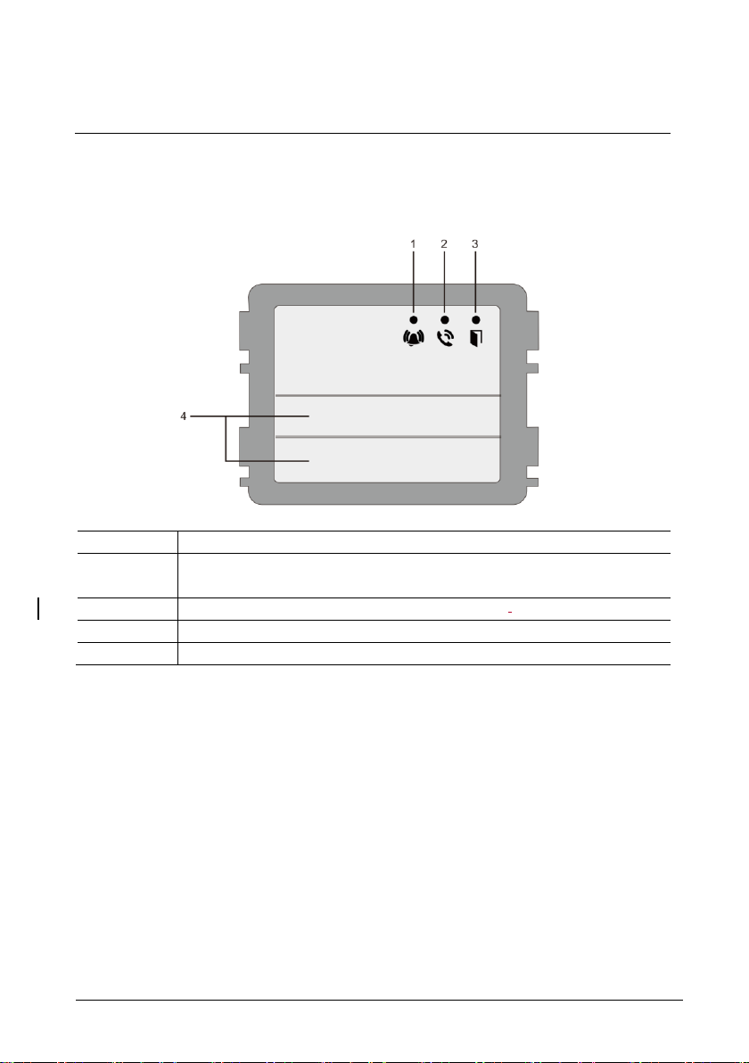
ABB-Welcome
Terminal description
|
— 7 —
No.
Function
1
LED flashes slowly, indicating a call has been established
LED flashes fast, indicating that the system is busy
2
LED illuminates, indicating possible communication.
3
LED illuminates, indicating the door is unlocked
4
Call pushbuttons
4 Terminal description
4.1 Audio module
Page 8
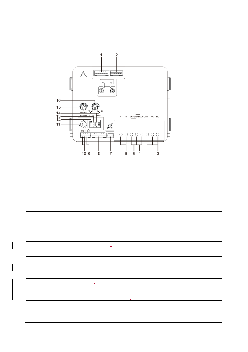
ABB-Welcome
Terminal description
|
— 8 —
No.
Functions
1
Connector for camera module
2
Connector for device software update
3
Plug-in clamps (COM-NC-NO) for floating output, door opener (30VAC/DC
1A)
4
Plug-in clamps (Lock-GND) for door opener (18V 4A impulsive, 250 mA
holding)
5
Plug-in clamps (DC-GND) for additional power supply
6
Plug-in clamps (a-b) for bus connection
7
Connector for induction loop module
8
Connector for next module
9
Connector for exit push button
10
Connector for sensor for checking the door status
11
Rotary switch for setting the address of OS (1-9)
12
Set feedback tones for push buttons and for outdoor station when making a
call: ON/OFF
13
Configure push buttons in a single column or double column mode (ON=
double column; OFF= single column)
It only affects the bar pushbutton, not the round pushbutton.
14
Configure functions of the 1st/2nd pushbuttons.
3->OFF, 4->OFF=call indoor station/call indoor station
3->ON, 4->OFF=switch on lighting/call indoor station
Page 9

ABB-Welcome
Terminal description
|
— 9 —
3->OFF, 4->ON=call guard unit/call indoor station
3->ON, 4->ON=switch on lighting/call guard unit
15
Adjust the loudspeaker volume.
16
*Adjust the door lock release time, 1-10s (available for the
lock connected with the default lock)
Page 10
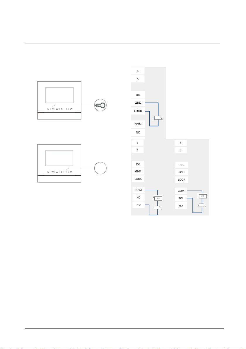
ABB-Welcome
Terminal description
|
— 10 —
1
*Default lock (1st lock): Released by “Unlock” button of the indoor station. Factory setting is
LOCK-GND.
2nd lock: Released by programmable button “1” of the indoor station. Factory setting is COMNC-NO.
Page 11
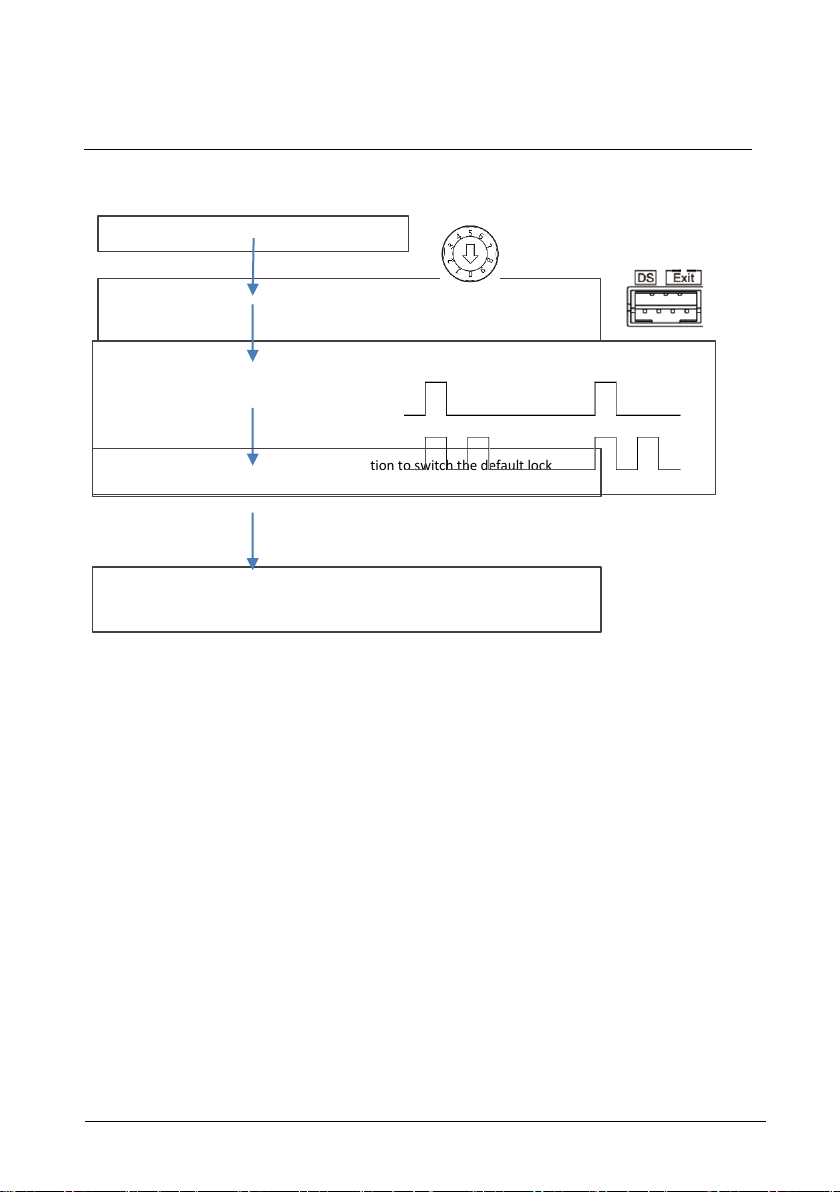
ABB-Welcome
Terminal description
|
— 11 —
Short circuit the "Exit" two terminals for 3s to enter the setting mode
(3 LED flashes green to show the setting mode for aluminum outdoor station)
(prompt tone “di” for stainless outdoor station)
Tones for indication:
Lock 1 (LOCK-GND) = default lock
Lock 2 (NC-NO-COM) = default lock
Set outdoor station address ="0"
30s overtime to save the setting and exit the programming mode
Short-circuit “Exit” terminal on outdoor station to switch the default lock
Change default lock
Default lock can be set at either "Lock-GND" or "NO-NC-COM"
Page 12
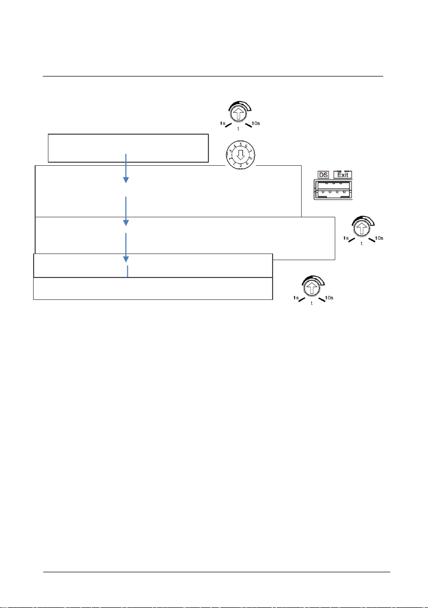
ABB-Welcome
Terminal description
|
— 12 —
Short circuit the “DS” two terminals for 3s to enter the setting mode
(3 LED flashes green to show the setting mode for aluminum outdoor station)
(Prompt tone “di” for stainless outdoor station)
Set outdoor station address ="0"
Record the time for 1st lock
Then set the time for 2nd-Lock from 1-10s
30s overtime to save the setting and exit the programming mode
At last set the time back for 1st-Lock
Recover the time to the original time for 1st lock
Set the lock time of the default lock
Set the time by th e potentiometer, from 1-10s
Set the lock time of the 2nd lock
Page 13
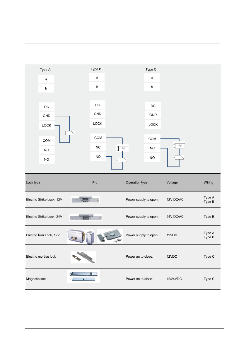
ABB-Welcome
Terminal description
|
— 13 —
4.1.1 Lock connected with terminals 3 and 4
Page 14
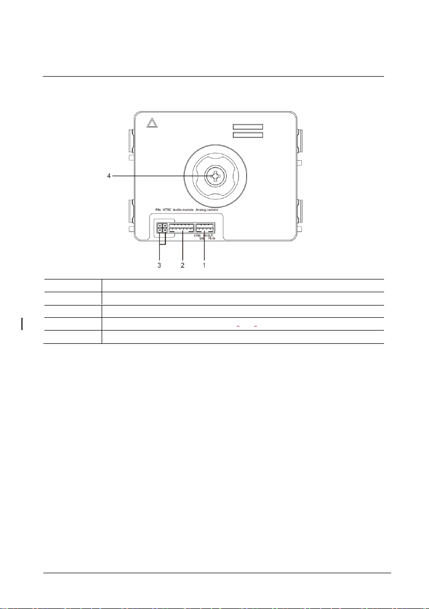
ABB-Welcome
Terminal description
|
— 14 —
No.
Functions
1
Connector for additional analog camera
2
Connector for audio module
3
Jumper for setting the video format: PAL /NTSC
4
Adjust the camera view area
4.2 Camera module
Page 15
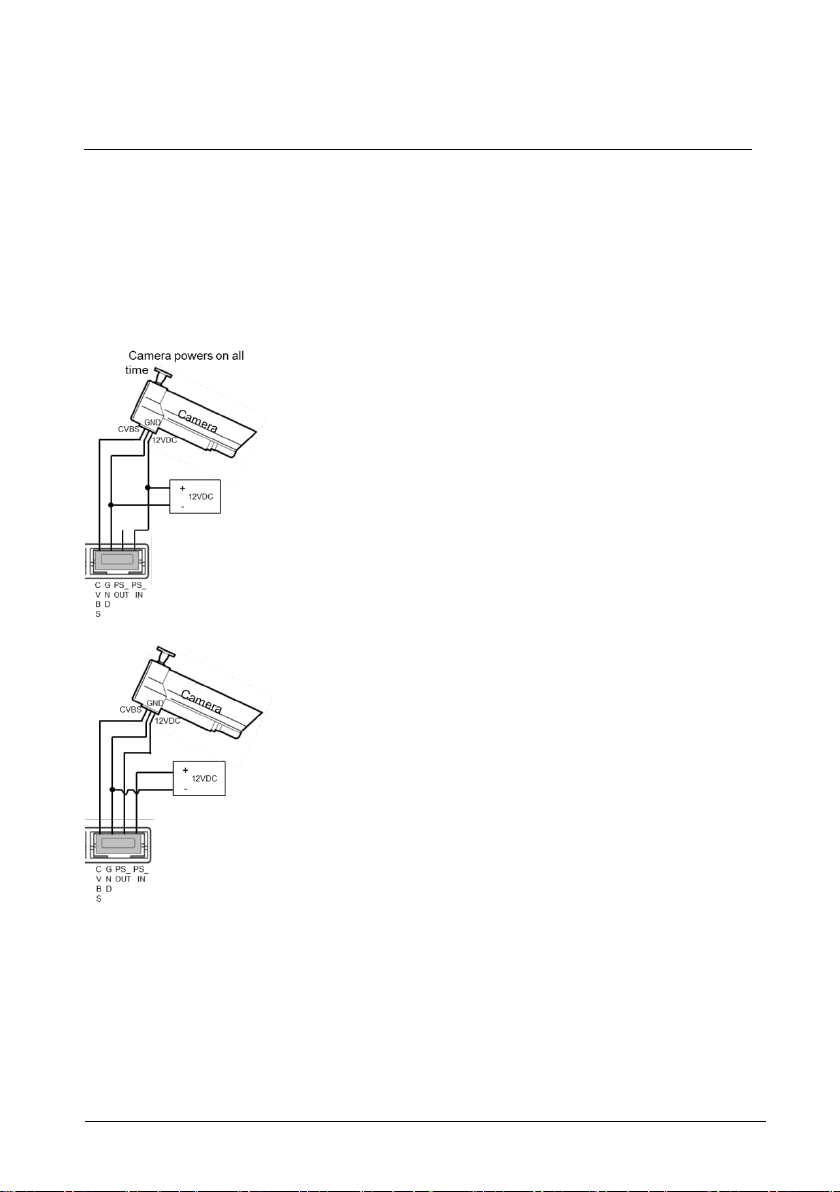
ABB-Welcome
Terminal description
|
— 15 —
4.2.1 Analog camera connected with terminal 1
All the cameras with the video output of 1Vp -p 75Ω ,CVBS (composite video broadcast signal)
can be connected with the camera module.
Generally, the transmission distance from the analog camera to the outdoor station can reach
up to 50 meters by coax cables or about 10 meters by other types of cables.
Two types of connections:
Option 1: The analog camera is powered on all the time
Option 2: The analog camera is powered on only during working hours
Page 16
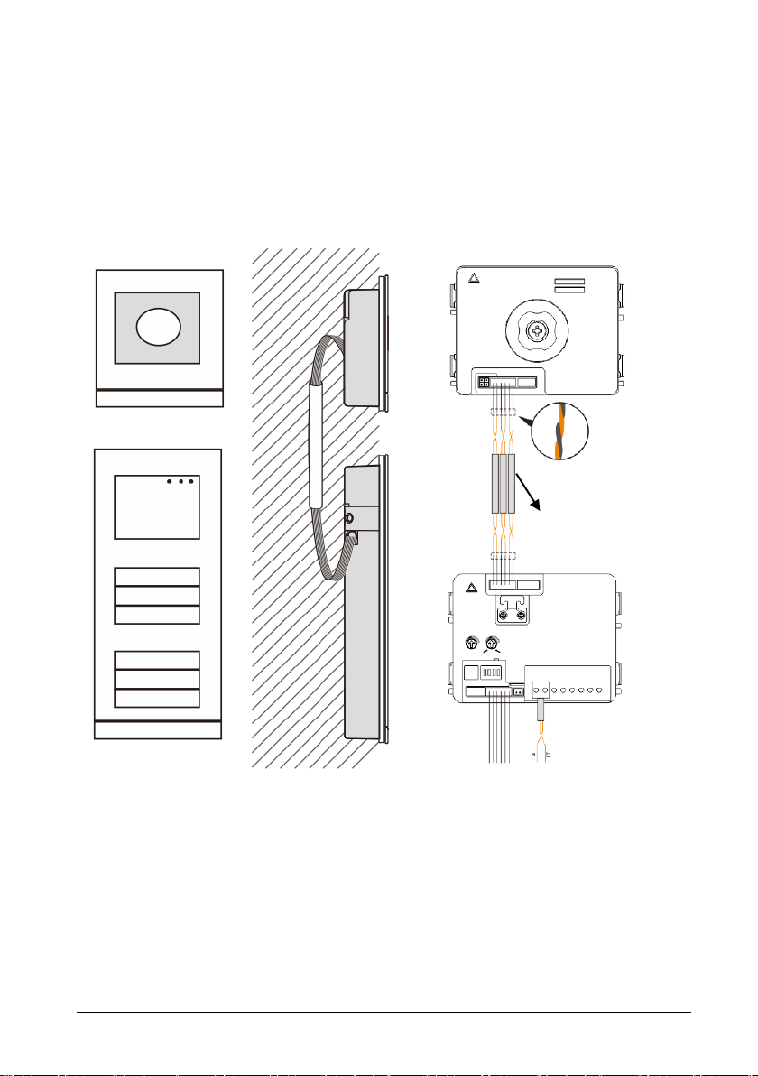
ABB-Welcome
Terminal description
|
— 16 —
3 pairs 2-wire bus
together
Max:10 metres
4.2.2 Detached camera connection
Camera module can be used as a detached camera. W iring is shown below.
Page 17
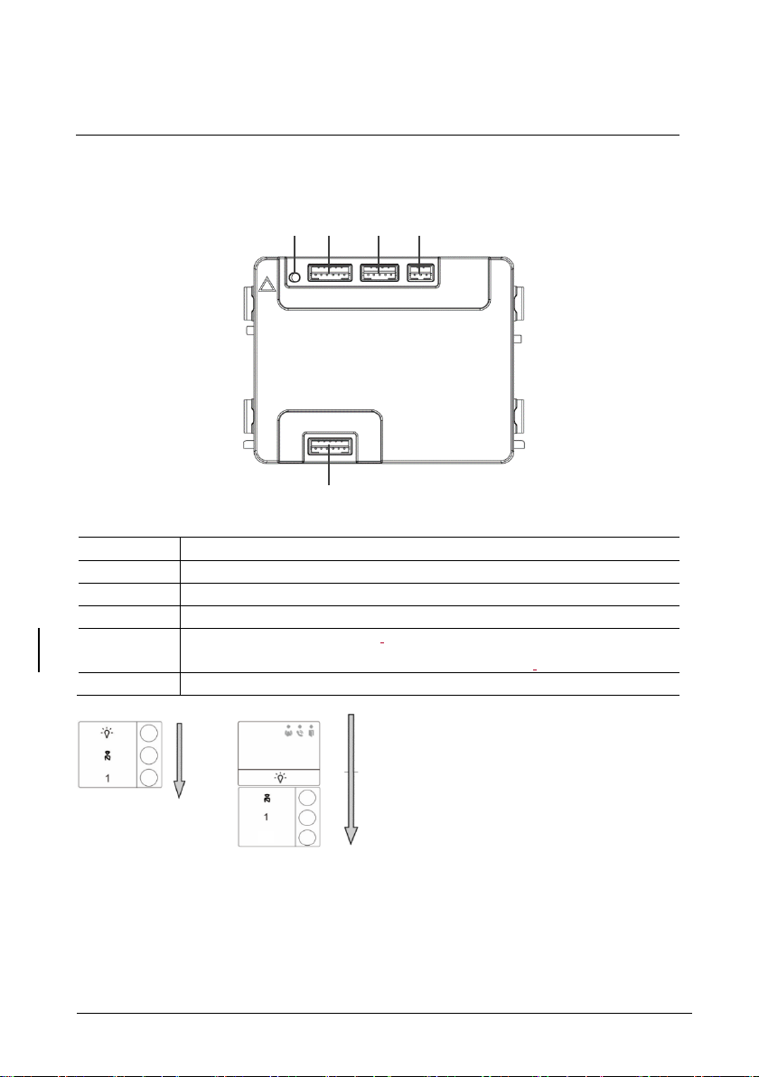
ABB-Welcome
Terminal description
|
— 17 —
No.
Functions
1
Program button
2
Connector for previous module
3
Connector for device software update
4
Connector for Wiegand output.
Default format is 26 bits, it can also be extended to 34 bits.
5
Connector for next module
1 2 3
4
5
2
4.3 Round pushbutton module
Page 18

ABB-Welcome
Terminal description
|
— 18 —
No.
Functions
1
Regardless of the structure of the pushbutton module, button numbers
are listed from top to bottom.
2
Lighting switch/call guard unit function is always assigned to the 1st/2nd
button, which is set by audio module.
3
User names can be printed by using the labellling tool of the ABB-Welcome
configuration software.
4
The round pushbutton module with NFC/IC card reader supports the
NFC/IC card. A mobile phone with NFC function is acceptable. (“Door
Open” APP required.)
Page 19
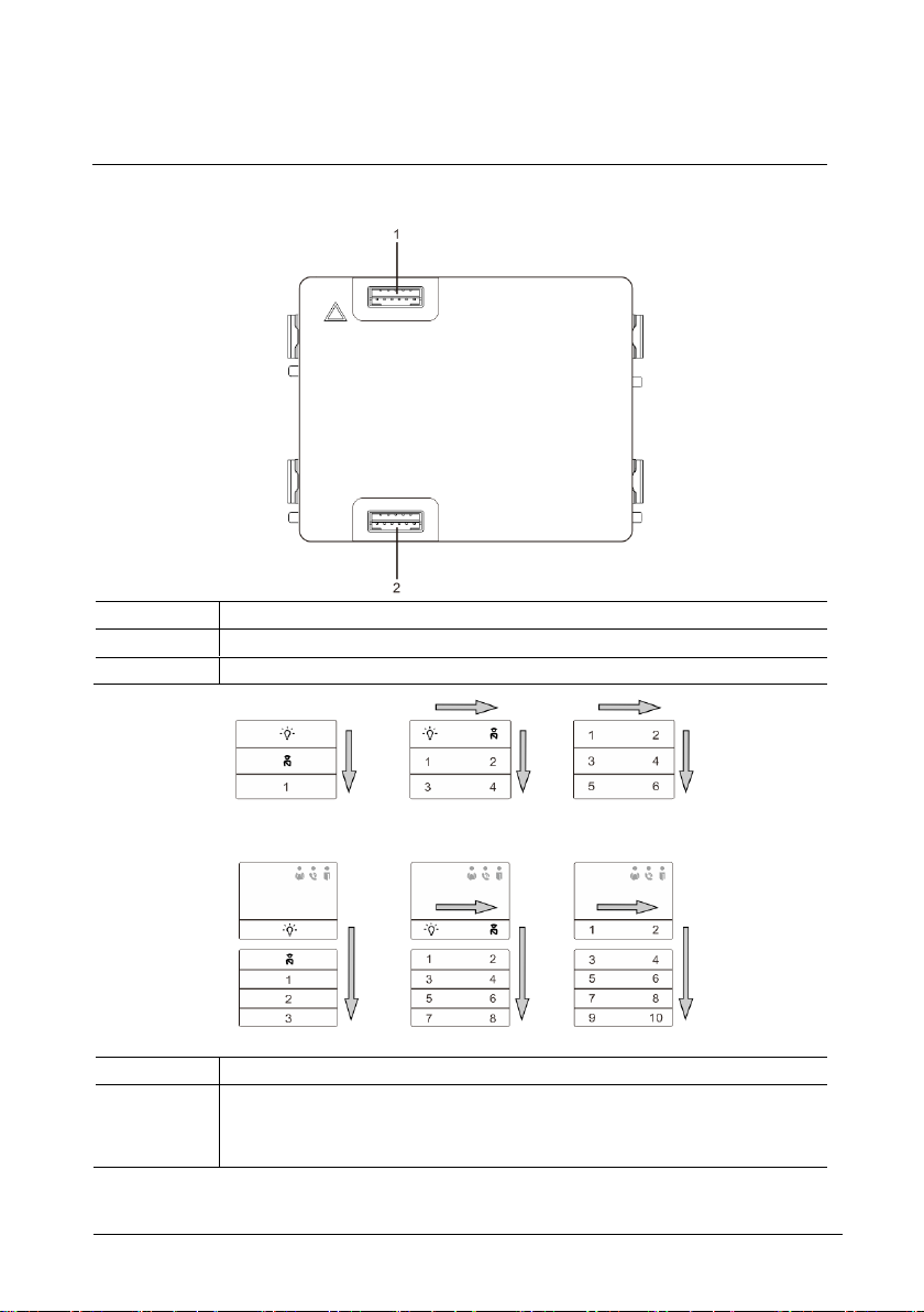
ABB-Welcome
Terminal description
|
— 19 —
No.
Functions
1
Connector for previous module
2
Connector for next module
No.
Functions
1
Regardless of the structure of the pushbutton module, the button numbers
are listed from top to bottom and from left to right (in the double column
mode.)
4.4 Pushbutton module
Page 20

ABB-Welcome
Terminal description
|
— 20 —
2
Lighting switch / call guard unit function is always assigned to the 1st/2nd
button.
3
User names can be printed by the using the labelling tool of the ABB-
Welcome configuration software.
Page 21
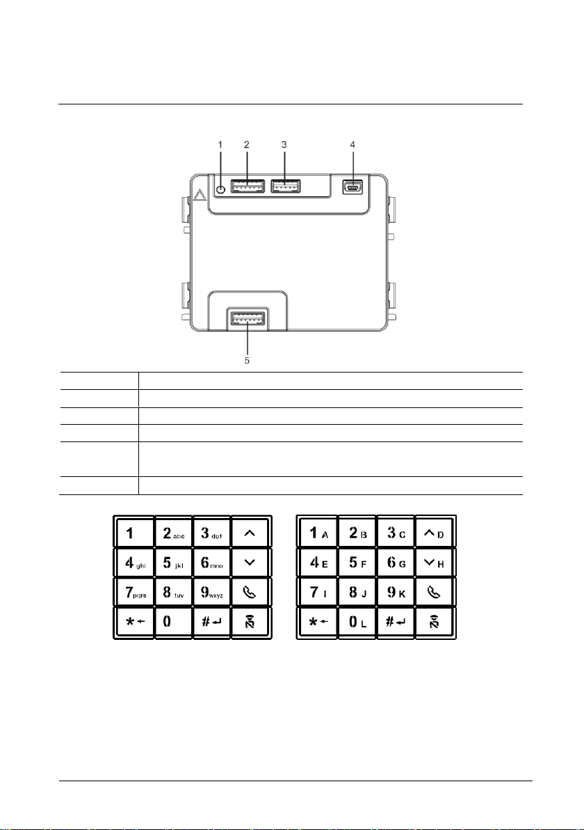
ABB-Welcome
Terminal description
|
— 21 —
No.
Functions
1
Program button
2
Connector for previous module
3
Connector for device software update
4
USB connector for connection to the PC: Download/upload the
configuration.
5
Connector for next module
4.5 Keypad module
Page 22
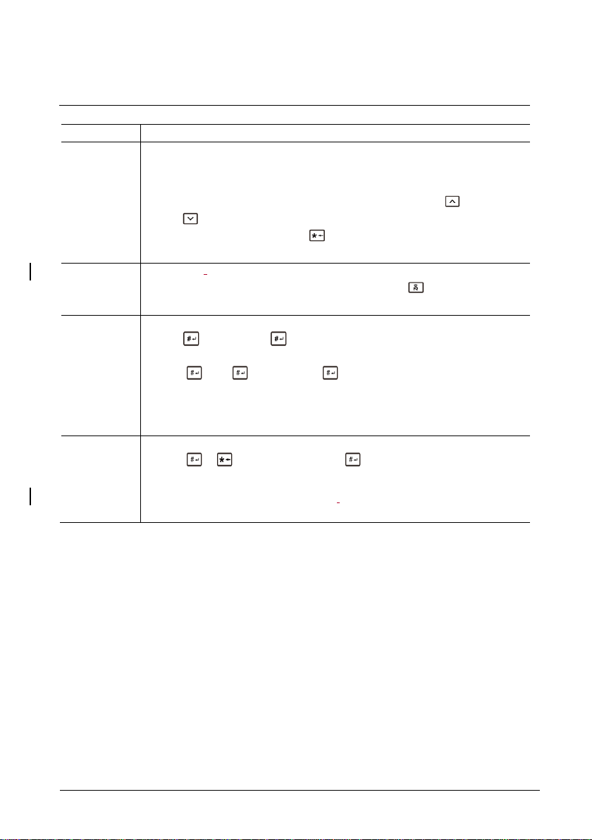
ABB-Welcome
Terminal description
|
— 22 —
No.
Functions
1
Call resident
A visitor inputs an indoor station number (001) or apartment number (e.g.
0101, programmed in advance) to call a resident.
*Also, the visitor can select a resident name with the button or the
button of the accompanying display module to make a call.
Meanwhile, pressing the button can cancel the call.
*This function is only available in Fig. 1.
2
Calling the guard unit
A visitor can call a guard unit by pressing the button if the guard unit is
available in the system.
3
Unlocking by password
Press" + password+ “to release the default lock to the audio
module.
Press " +2 + + password + " to release the 2nd lock connected
to the audio module.
The initial password is 123456. Residents can set their own customized
password with indoor stations.
4
System engineering configuration
Press " + + system password + " to enter the system
engineering configuration menu.
The initial system password is 345678, and it can be modified by the
administrator.
Page 23
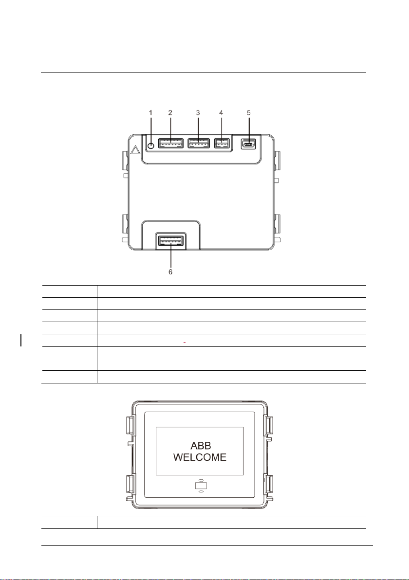
ABB-Welcome
Terminal description
|
— 23 —
No.
Functions
1
Program button
2
Connector for previous module
3
Connector for device software update
4
Connector for Wiegand output
5
USB connector for connecting to the PC: Download/upload the
Configuration.
6
Connector for the next module
No.
Functions
4.6 Display and card reader module
Page 24

ABB-Welcome
Terminal description
|
— 24 —
1
LCD display
2
Supports ID or IC card.
Swipe the registered card to release the door lock. The card can be
programmed through the module itself, or by using a PC to download the
program file. (M251021CR is accompanied with an ID card reader, while
the M251022CR is accompanied with an IC card reader.)
3
Support Wiegand output.
The default Wiegand format is 26 bits, but it can also be extended to 34
bits.
*The display module must be connected after audio module.
Page 25

ABB-Welcome
Terminal description
|
— 25 —
Work
frequency
125KHz
Standard
ISO18000-2
Support
card
EM4100, EM4205, EM4305, EM4450, TK4100, T5567/T5577 Compatible
HID 2
Output
format
Wiegand 26, 34 bit
Work
frequency
13.56MHz
Standard
ISO 14443A
Support
card
Mifare One S50/S70, etc.
Output
format
Wiegand 26, 34 bit
No.
Functions
Technical specification
M251021CR: Display module with ID card reader
M251022CR: Display module with IC card reader
4.7 Nameplate module
Page 26

ABB-Welcome
Terminal description
|
— 26 —
1
Connector for previous module
2
Connector for next module
Labeling of the nameplate module can be printed by using the labelling tool of the ABBWelcome configuration software.
Pos: 18 /DinA4 - Anleitungen Online/Ueb erschriften/1./Bedienung @ 18\mod_1302613924165_1 5.docx @ 103365 @ 1 @ 1
Page 27

ABB-Welcome
Operation
|
— 27 —
No.
Functions
1
3->OFF, 4->OFF
2
Call apartment 01
3
Call apartment 02
4
Call apartment 03
3
4
DIP
1
2
3
1
2
3
4
001
002
003
5 Operation
Pos: 19 /DinA4 - Anleitungen Online/Ueb erschriften/2./Normaler Betrieb @ 18\mod_1302768820 965_15.docx @ 103540 @ 2 @ 1
5.1 Pushbutton outdoor station
Pos: 20 /DinA4 - Anleitungen Online/Ueb erschriften/3./Bedienelemente @ 20\mod_132326022 0559_15.docx @ 111647 @ 3 @ 1
5.1.1 Addressing
1. Configure functions of the 1st/2nd pushbutton
Page 28

ABB-Welcome
Operation
|
— 28 —
No.
Functions
1
3-> ON, 4->OFF
2
Switch on light. The light is connected with a switch actuator. The address
of the switch actuator must be the same as the address of this outdoor
station.
3
Call apartment 01
4
Call apartment 02
No.
Functions
1
3-> OFF, 4-> ON
2
Call the guard unit. If there are multiple guard units in the same section, all
guard units will ring at the same time when a visitor presses the button
“call guard unit.”.
3
Call apartment 01
4
Call apartment 02
3 4 DIP
1
2
1 2 3
4
001
002
3 4 DIP 1 2
1 2 3
4
001
002
Guard unit
Page 29

ABB-Welcome
Operation
|
— 29 —
No.
Functions
1
3-> ON, 4-> ON
2
Switch on lights
3
Call guard unit
4
Call apartment 01
3 4 DIP
1
1 2 3
4
001
Guard unit
Page 30

ABB-Welcome
Operation
|
— 30 —
No.
Functions
1
2-> OFF
2
Call apartment 01
3
Call apartment 02
4
Call apartment 03
5
Call apartment 04
No.
Functions
1
2-> ON
2
Call apartment 01
3
Call apartment 02
4
Call apartment 03
5
Call apartment 04
6
Call apartment 05
7
Call apartment 06
2
ON
1 2 3
5
1
2
3
4
4
001
002
003
004
2
ON
1 3 5 9 7 2 4 8 6
2 4 6 8 1 3 5
7
001
001
002
003
004
005
006
007
008
2. Configure pushbutton in single or double column modes
Page 31

ABB-Welcome
Operation
|
— 31 —
8
Call apartment 07
9
Call apartment 08
No.
Functions
1
2-> ON,3-> ON, 4-> ON
2
Switch on lights
3
Call the guard unit
4
Call apartment 01
5
Call apartment 02
6
Call apartment 03
7
Call apartment 04
8
Call apartment 05
9
Call apartment 06
3
4
DIP
1
2
ON
3
5
9
7
2
4
8
6
2
4 6 1
3
5
Guard unit
001
002
003
004
005
006
5.1.2 Setting the language for the voice messages (if the audio
module has a speech synthesis function)
If the audio module with a speech synthesis function (M251024A-.), the local language
can be set.
Set outdoor station address as “0” and hold the 1st button for 3s to play the voice
message.
Click on this button to select the language.
After choosing the language, hold this button t o save and exit t he set ting.
Page 32

ABB-Welcome
Operation
|
— 32 —
1 2 3
4
2 4 6 8 3
5
7
Single column
Double column
1
1st button
Page 33

ABB-Welcome
Operation
|
— 33 —
Apartment 01 A
Apartment 02 B
Apartment 03 C
Apartment 04 A
Apartment 05 B
Apartment 06 C
Outdoor station
Left building
Apartment 01 A
Apartment 02 B
Apartment 03 C
Apartment 04 D
Apartment 05 E
Apartment 06 F
Outdoor station
Gate entrance
Outdoor station
Right building
Pushbutton outdoor station used as gate station
If pushbutton outdoor station is set as a gate station, the gateway as an important
system device must be used and it must be set as floor gateway mode.
For detailed information, please refer to the Gateway User Manual, floor gateway
chapter.
Pos: 71 /DinA4 - Anleitungen Online/Ueb erschriften/3./Abschlusswiderstand @ 19\mod_1321 958079906_15.docx @ 110083 @ 3 @ 1
Pos: 72 /DinA4 - Anleitungen Online/Inhalt/ KNX/DoorEntry/Bedienung/Abschlusswiderstand setze n 83220-AP-xxx @ 19\mod_1310723392369_15.d ocx @ 107841 @ @ 1
Page 34

ABB-Welcome
Operation
|
— 34 —
The display and card reader module can be
assembled with a push button outdoor station. The
user can swipe cards to open the door. For this
combination, a master card is needed for an
electrician to manage this outdoor station.
Register a master card/deactivate master card. (We
recommend that this work is carried out by specialized
personnel.)
1. Disconnect the power supply.
2. Reconnect the power
3. Hold the “program button” for 5s to enter
"program master card" interface within 30s.
4. Any card swiped by the reader during this time
will be taken to be the new MASTER card. A
prompt “Register master card successfully” will
appear on the screen.
If the card exists, when you swipe it again, the
information will be deleted, and a prompt “Delete
master card successfully" will appear on the
screen.
Only 1 master card can be registered.
5.2 Pushbutton outdoor station with display module
Enter system setting using master card:
1. Swipe the MASTER card to enter the setting menu. Three LEDs will turn on.
2. 6 options:
Program card
Language
Wiegand output
Choose door
Date and time
Back
There is a 5s countdown for each option.
3. Swipe the MASTER card again within 5s to change to the next option.
Or, 5s over, the current option will be chosen.
Page 35

ABB-Welcome
Operation
|
— 35 —
Menu_________05
Program Card
Language
Wiegand Output ∨
Swipe the MASTER
card
Menu_________05
Program Card ∧
Language
Wiegand Output ∨
Swipe the MASTER
card within 5s to move
to next option.
==>
Menu_________√
Program Card
Language
Wiegand Output ∨
5s over, choose current
option
==>
==>
Menu_________05
Program Card ∧
Language
Wiegand Output ∨
Swipe the MASTER
card within 5s to move to
next option.
==>
==>
Proximity Card 05
Register Card
∧
Delete Card
Delete All ∨
Swipe the MASTER
card, enter the setting
4. 30s over, to exit the settings menu.
--- ∧
--- ∧
--------
---
Page 36

ABB-Welcome
Operation
|
— 36 —
The keypad module can be assembled with a push
button outdoor station and users can enter the
password to open the door.
Users can enter the system settings menu by using
the following steps. (Press # to confirm and * to
cancel. The default system password is 345678.)
1. Set the device as an outdoor station or a gate
station.
Outdoor station:
#* system password # =>
1 # => 1 #
Gate Station:
#* system password # =>
1 # => 2 #
5.3 Pushbutton outdoor station with keypad module
2. Modify "system password"
#* system password # =>
2 # => Enter new password (6-8 bits) # => Enter the password again #
3. Modify "door open code"
#* system password # =>
3# => Enter new door open code (3-8 bits) # => Enter the code again #
4. Set the voice message
If the audio module with the speech synthesis function (M251024A-.) is assembled,
the local language can be set.
#* system password # =>
4# => Press or to choose the language => #
5. Enable/disable access control function
Enable access control function:
#* system password # =>
5# => 1 #
Disable access control function:
#* system password # =>
Page 37

ABB-Welcome
Operation
|
— 37 —
5# => 2 #
*Reset the system password of keypad module:
It is possible to reset the system password to the factory setting if you have forgotten it.
The restoration of default factory settings does not delete the rest of the information
programmed on the system, such as user names and other settings.
1. Disconnect the power supply.
2. Reconnect the power.
3. Hold the “program button” for 5s within 30s.
4. A “di” will sound and the system password will be reset to the default (345678).
Page 38

ABB-Welcome
Operation
|
— 38 —
Function
Command
LED
Create admin card
Swipe card 1x
Green
Enter settings
Swipe admin card 1x
Orange
Function
Command
LED
Enroll user
Swipe admin card 1x
Orange flash 1x
Swipe card (new user) 1x
Green
Delete user
Swipe admin card 2x
Orange flash 2x
Swipe card (user x) 1x
Green
Enroll new admin
Swipe admin card 3x
Orange flash 3x
Swipe card (new admin) 1x
Green
Delete admin
Swipe admin card 4x
Orange flash 4x
Swipe card (admin x) 1x
Green
Delete all users
Swipe admin card 5x
Orange flash quickly
Swipe admin card 1x
Green
Function
Command
LED
Exit settings
Swipe admin card 1x or no cards
swiped within 15 seconds
——
Function
Command
LED
Open a door
Swipe the enrolled keycard or mobile phone
with “Door Open” App installed.
Green
5.4 Round pushbutton outdoor station with IC/NFC
Enroll the cards
For round pushbutton module with NFC/I C card reader, cards can be enrolled or deleted. A maximum
of 500 cards can be s upported.
Prog ramming
The system will take the first card swipe d after po wering up the system within
60s to be the admin card.
After entering settings, the following fun ctionalities can be imp lemen ted:
During s etting, please swipe th e same admin card.
Open a d oor
Page 39

ABB-Welcome
Operation
|
— 39 —
Function
Command
LED
Reset to factory
default
Disconnect the power supply.
Reconnect the power supply.
Long-press the “program” button for 5s
within 60s.
Finish reset.
——
White
Red, green,
orange cycle
——
Work frequency
13.56MHz
Standard
ISO 14443A
Support card
Mifare One S50/S70, etc.
Output format
Wiegand 26, 34 bit
Support NFC device
Mostly NFC mobile. (Not all; tested is needed before using this function.)
Rese t to factory de fault
Technical specifications for ro und pushbutton modu le with IC/NFC :
Page 40

ABB-Welcome
Operation
|
— 40 —
26 bit, green LED flash *1
34 bit, green LED flash *2
Switch on validation, green LED flash*1
Switch off validation, green LED flash*2
Set the Wiegand format
1. Swipe admin card to enter system setting. (Orange LED is on.)
2. Short press 1st button to change the Wiegand format to 26 bit or 34 bit. (Default is 26 bit .)
The different format is indicated by the LED and sound feedback.
Switch off validation
In some case, the users only register cards as a third party and not on outdoor station. When
the users swipe these cards at the outdoor station the door will be opened, but a warning
indication will be displayed on display module. It is not necessary to play this warning.
Therefore, validation needs to be switched off so that wrong indication on display module will
not appear, even though the card is not enrolled at this outdoor station.
1. Swipe admin card to enter system setting. (Orange LED is on.)
2. Long press 1st button for 3s to switch validation on/off. (Default validation is “on.”)
The status on/off is indicated by the LED and sound feedback.
Page 41

ABB-Welcome
Operation
|
— 41 —
Use app to open door
Round pushbutton module with NFC can be used for opening doors. Programming is carried
out directly on the module or via a web browser (requires IP gateway 83342-500). Additional
devices are not required for commissioning.
To the play store
(https://play.google.com/store/apps/details?id=com.abb.allegro3_nfcdooropener&hl=en)
1. Download and install the ABB door opener app from Google Play Store.
2. Turn on the NFC function of your device.
3. Enter setting mode of your round pushbutton module.
4. Start the app at your device.
5. Set up your device as new user.
6. Configure your personal settings.
Page 42

ABB-Welcome
Operation
|
— 42 —
1. Physical address
The physical address is the internal code that the
outdoor station will send through the bus connection
to indoor stations or other devices in the system. For
each apartment, physical address means the address
of an indoor station that is installed in the apartment.
For each building, physical address means the
address of a gateway that is installed for each
building. It is also called the building number.
In standby mode, a visitor can press the physical
address corresponding to the residence (from 001 to
250).
For a complex building, a visitor needs to press the
building number (01- 60) plus the physical address
(001 - 250), or make a call in the gate station.
Enter Physical
Add.:
5.5 Keypad outdoor station
5.5.1 Call a resident (3 types)
01 001
2. Logic address
Logic address is a code that a visitor can press to make a call. The code must be
assigned first and then associated with the physical address.
The apartment number or some special codes can be used to set the logic address,
which is easy for the users to remember.
Set the logic address by following these steps:
Assign the logic address:
#* system password # => system setting =>
Contact => Add => Logic Add.
Page 43

ABB-Welcome
Operation
|
— 43 —
Physical Add.:
Logic Add.:
Call Mode_______
Physical Add. ∧
Logic Add.
==>
No. of digit:
Physical Add.:
User Name:
001
0101
Turn on the “Logic address” call mode
#* system password # => system setting =>
Configurations => Call Mode
--------
∨
3. Resident name
(Note: This function is only available for the outdoor station with a keypad module
(M251021K-.)
In standby mode, press the button or the button to display resident names. Use
the buttons and to search for the desired residential station and press the button
to make a call.
Also, a visitor can enter the resident name using the keypad to make a call.
Resident names must be assigned first and then associated with the physical address.
#* system password # => system setting
=> Contact => Add => User Names
-4-
(1-8 Digits)
01001
Federico
Page 44

ABB-Welcome
Operation
|
— 44 —
30 s
“*“ to Cancel
==>
120 s
“*“ to Cancel
Accept the call
30 s
“*“ to Cancel
==>
120 s
“*“ to Cancel
Playing the message...
==>
001 s
“*“ to Cancel
After a “di” sound, visitor
can record the message
5.5.2 Call the guard unit
Press the button to make a call to a guard unit.
Guard Unit
Guard Unit
5.5.3 If an indoor station is in “leave home mode”
If an indoor station works in the “leave home mode,” a visitor can record a
message for the resident after entering the following interface.
Andy
Andy
Recording...
Page 45

ABB-Welcome
Operation
|
— 45 —
Guard unit accepts
the call
Guard unit transfers the
call to an indoor station
30 s
“*“ to Cancel
==>
120 s
“*“ to Cancel
Call from an outdoor
station to an indoor
station
==>
120 s
“*“ to Cancel
==>
5.5.4 If a guard unit is in "intercept mode"
If a guard unit works in the “intercept mode,” the call from an outdoor station to
an indoor station will be intercepted by the guard unit and after the identity is
confirmed, the guard unit will forward the call to the indoor station.
Guard Unit
Andy
Guard Unit
Page 46

ABB-Welcome
Operation
|
— 46 —
Menu__________
Configurations
Access Control
Contact
Device Type_____
Outdoor St.
∧
Gate Station
Device Type_____
Outdoor St.
Gate Station
Call mode_______
Physical Add.
Logic Add.:
5.5.5 System settings
(In settings, press “#” to confirm and “*” to cancel. The default system password is
345678.)
1. Enter the system settings menu
#* system password #
-- ∧
∨
2. Configurations
(1) Set the device as an outdoor station or a gate station.
Outdoor station:
#* system password # =>
Configurations # => Device Type # => Outdoor St. # (Default)
● --
∨
Gate station:
#* system password # =>
Configurations # => Device Type # => Gate station #
(2) Set the call mode: Make a call by a physical address or a logic code.
Set the call mode by Physical Address:
#* system password # =>
Configurations # => Call mode # => Physical Address #
∧
●-
∨
●
Page 47

ABB-Welcome
Operation
|
— 47 —
Call Mode_______
Physical Add.
Logic Add.:
New Password:
==>
Re-enter:
==>
Reset System
Code?
“#” to Confirm
“*” to Cancel
==>
Set the call mode by a Logic Code (1-8 digits).
#* system password # =>
Configurations # => Call mode # => Logic Code #
∧
●-
∨
(3) System password setting
Modify the system password
#* system password # =>
Configurations # => System code # => Modify #
******
Reset the system password
#* system password # =>
Configurations # => System code # => Reset #
******
Done!
Done!
Page 48

ABB-Welcome
Operation
|
— 48 —
Door Open Code__
Disable
Modify
Reset
==>
New Password:
==>
Re-enter:
==>
Reset Door Open
Code?
“#“ to Confirm
“*“ to Cancel
==>
3. Access control
(1) Door open code
The password can be set using 3-8 digits. The default door open password is
"123456” and it can be changed at an outdoor station.
Users can set their own passwords at the indoor stations. A total of 6,000
passwords can be stored.
Set the door open password ON/OFF (default: 123456)
#* system password # =>
Access Control # => Door open code # => Enable/disable #
-- ∧
∨
Modify the door open password
#* system password # =>
Access control # => Door open code # => Modify #
******
Reset the door open password
#* system password # =>
Access control # => Door open code # => Reset #
Done!
******
Done!
Done!
Page 49

ABB-Welcome
Operation
|
— 49 —
Enter Card No.:
0123456
Or
Swipe the Card
==>
Enter Card No.:
0123456
Or Done!
Swipe the Card
Enter Card No.:
0123456
Or
Swipe the Card
==>
Enter Card No.:
0123456
Or Done!
Swipe the Card
Delete All
Cards?
“#” to Confirm
“*” to Cancel
==>
Physical Add.:
001
User Name:
Alexander.G
(2) Proximity card (3,000 cards can be registered for outdoor station.)
Register cards:
#* system password # =>
Access control # => Proximity card # => Register card #
Delete cards:
#* system password # =>
Access control # => Proximity card # => Delete card #
Delete all cards
#* system password # =>
Contact # => Proximity card # => Delete All #
Done!
4. Contact (3,000 names using a combination of 24 alphanumeric characters)
(1) Add
Add the contact by user names
#* system password # =>
Contact # => Add # => User Names #
Page 50

ABB-Welcome
Operation
|
— 50 —
Physical Add.:
001
Logic Add.:
0101
Alexander.G
Bodin.K
Christian.G
Enter Logic
Add.:
0101
Resident names must be associated with a physical address.
Add the contact by logic address
#* system password # =>
Contact # => Add # => Logic add. #
Logic address must be associated with a physical address.
(2) Modify
Modify contact by user names
#* system password # =>
Contact # => Modify # => User Names #
-- ∧
∨
Modify the resident names with the corresponding physical address.
Modify contact by logic address
#* system password # =>
Contact # => Modify # => Logic add. #
Modify the logic address and its corresponding physical address using the
alphanumeric keypad.
(3) Delete
Delete the contact by user names
#* system password # =>
Contact # => Delete # => User Names #
Page 51

ABB-Welcome
Operation
|
— 51 —
Alexander.G
Bodin.K
Christian.G
Enter Logic
Add.:
0101
Delete All Names?
“#” to Confirm
“*” to Cancel
==>
-- ∧
∨
Delete the contact by logic address
#* system password # =>
Contact # => Delete # => Logic add. #
(4) Clear all
#* system password # =>
Contact # => Clear all #
Done!
Clear all lists including resident names and logic address entries from this menu.
Page 52

ABB-Welcome
Operation
|
— 52 —
“#” to Confirm
==>
2nd-Lock Open
Time (1-10s):
“#” to Confirm
==>
Voice Message___
On
Off
==>
No This Function!
5. System setting
(1) Date and time
#* system password # =>
Settings # => Date & time # => Enter time and date => #
2016-01-01
07:00
Done!
(2) Door open time for 2nd lock
#* system password # =>
Settings # => Door Open Time # => Time 1-10s (default: 3s) => #
3s
(3) Setting the voice message on/off
If the audio module with the speech synthesis function (M251024A-.) is assembled,
the speech synthesis function can be enabled or disabled. Meanwhile, the local
language can be chosen, too.
#* system password # =>
Settings # => Voice message #
● -- ∧
Done!
Done!
∨
If the audio module does not have a speech synthesis function, this will be indicated
when user enters the menu.
(4) Select language
Page 53

ABB-Welcome
Operation
|
— 53 —
Language_______
English
Français
Italiano
New Message:
ABB-Welcome!
“#” to Confirm
“*” to Cancel
==>
Wiegand Output__
26 bit !
34 bit !
Choose Door____
1st-Lock
2nd-Lock
#* system password # =>
Settings # => Language #
● -- ∧
∨
(5) Welcome Msg.
#* system password # =>
Settings # => Welcome Msg. #
Done!
A total of 64 characters can be entered.
(6) Setting the Wiegand output digits
#* system password # =>
Settings # => Wiegand Output #
∨
(7) Set the related door lock when swiping the card
#* system password # =>
Settings # =>Choose Door #
∨
Setting the lock that will be released when swiping the registered card:
(8) Reset
● -- ∧
●∧
Page 54

ABB-Welcome
Operation
|
— 54 —
Reset to Factory
Default?
“#” to Confirm
“*” to Cancel
==>
Audio module: ∧
V1.07_131106
Card reader:
V0.10_131107 ∨
#* system password # =>
Settings # => Reset # => #
Done!
Reset all settings to factory settings, but other information, e.g. user names, logic
addresses and card information cannot be reset.
(9) Information
#* system password # =>
Settings # => Information #
View the software information of each modules of the outdoor station.
Page 55

ABB-Welcome
Operation
|
— 55 —
*Reset the system password of keypad module:
It is possible to reset the system password to factory settings if you have forgotten it.
The restoration of default factory settings does not delete the other information
programmed on the system, such as user names and other settings.
1. Disconnect the power supply.
2. Reconnect the power
3. Hold the “program button” for 5s within 30s.
4. A “di” will be sounded and the system password will be reset to the default
(345678).
Pos: 67 /DinA4 - Anleitungen Online/Ueb erschriften/2./Reinigung @ 19\mod_1310733980533_1 5.docx @ 107853 @ 2 @ 1
Page 56

ABB-Welcome
Operation
|
— 56 —
In standby mode, a visitor can enter the physical
address corresponding to the residence to call
directly, from 001 to 250.
For a complex building, the visitor needs to press the
building number (01-60) plus physical address (001-
250) to make a call from a gate station.
5.6 Keypad outdoor station without display (camera + audio +
keypad)
5.6.1 Calling a resident by inputting physical address
5.6.2 Call guard unit
Press the button to make a call to a guard unit.
5.6.3 System settings
Users can enter the system settings by following these steps. (In settings, press “#” to
confirm, press “*” to cancel. The default system password is 345678.)
1. Set the device as an outdoor station or a gate station.
Outdoor station:
#* system password # =>
1 # => 1 #
Gate station:
#* system password # =>
1 # => 2 #
2. Modify the "system password"
#* system password # =>
2 # => Enter new password (6-8 bits) # => Enter the password again #
3. Modify the "door open code"
#* system password # =>
3# => Enter new door open code (3-8 bits) # => Enter the code again #
4. Setting the voice message
If the audio module with the speech synthesis function (M251024A-.) is assembled,
the local language can be set.
Page 57

ABB-Welcome
Operation
|
— 57 —
#* system password # =>
4# => Press or to choose the language => #
5. Enable/disable the access control function
Enable access control function:
#* system password # =>
5# => 1 #
Disable access control function:
#* system password # =>
5# => 2 #
*Reset the system password of keypad module:
It is possible to reset the system password to the factory setting if you have forgotten it.
The restoration of default factory settings does not delete the other information
programmed on the system, such as user names and other settings.
1. Disconnect the power supply.
2. Reconnect the power.
3. Hold the “program button” for 5s within 30s.
4. A “di” will be sounded and the system password will be reset to the default
(345678).
Pos: 21 /DinA4 - Anleitungen Online/Inhalt/ KNX/DoorEntry/83220-AP-xxx/Bedienelemente - 83220-AP- xxx @ 18\mod_1303212853605_15.docx @ 103673 @ @ 1
2149 @ @ 1
Page 58

ABB-Welcome
Advanced
configuration
|
— 58 —
Pos: 70 /DinA4 - Anleitungen Online/Ueb erschriften/2./Geraeteeinstellungen @ 18\mod_130276 8847744_15.docx @ 103548 @ 2 @ 1
6 Advanced configuration
Connect to the PC to configure the keypad or display
Pos: 75 /Busch-Jaeger (Neustruktur)/Mo dul-Struktur/Online-Dokumentation/Steuermodule - Onli ne-Dokumentation (--> Für alle Dokumente <--)/++++++++++++ Seitenumbruc h ++++++++++++ @ 9\mod_1268898668093_0.doc x @ 52149 @ @ 1
Page 59

ABB-Welcome
Technical data
|
— 59 —
Designation
Value
Operating temperature
-40 ℃ - +70 ℃
Protection (cover frame
assembled)
IP 54
Power supply, door opener
(Lock-GND)
18V 4A impulsive, 250 mA holding
Floating output, door opener
(COM-NC-NO)
30 V AC / DC 1A
Single-wire clamps
2 x 0.28 mm2 - 2 x 0.75 mm2
Fine-wire clamps
2 x 0.28 mm2 - 2 x 0.75 mm2
Bus voltage
20-30 V
Pos: 76 /DinA4 - Anleitungen Online/Ueb erschriften/1./Technische Daten @ 18\mod_130261586 3001_15.docx @ 103416 @ 1 @ 1
7 Technical data
Pos: 77 /DinA4 - Anleitungen Online/Inhalt/ KNX/DoorEntry/83220-AP-xxx/Technische Daten - 83220-AP-xxx @ 1 8\mod_1303212854559_15.docx @ 103705 @ @ 1
Pos: 78 /Busch-Jaeger (Neustruktur)/Mo dul-Struktur/Online-Dokumentation/Steuermodule - Onli ne-Dokumentation (--> Für alle Dokumente <--)/++++++++++++ Seitenumbruc h ++++++++++++ @ 9\mod_1268898668093_0.docx @ 52149 @ @ 1
Page 60

ABB-Welcome
Mounting/installation
|
— 60 —
Warning
Electric voltage!
Risk of death and fire due to electrical voltage of 100-240 V.
– Low-voltage and 100-240 V cables must not be installed together
in a flush-mounted socket!
In case of short-circuit, there is the danger of a 100-240 V load on
the low-voltage line.
Warning
Electric voltage!
Install the device only if you have the necessary electrical engineering
knowledge and experience.
• Incorrect installation endangers your life and that of the user of
the electrical system.
• Incorrect installation can cause serious damage to property, e.g.,
fire.
The minimum necessary expert knowledge and requirements for the
installation is as follows:
• Apply the "five safety rules" (DIN VDE 0105, EN 50110):
1. Disconnect from power source;
2. Secure against being re-connected;
3. Ensure that there is no voltage;
4. Connect to the earth;
5. Cover or barricade adjacent live parts.
• Use suitable personal protective clothing.
• Use only suitable tools and measuring devices.
• Check the type supply network (TN system, IT system, TT system)
to secure the following power supply conditions (classic
connection to the ground, protective grounding, necessary
additional measures, etc.).
Pos: 79 /Busch-Jaeger (Neustruktur)/Mo dul-Struktur/Online-Dokumentation/Überschriften (--> Für alle Dokument e <--)/1. Ebene/M - O/Montage / Installation @ 18\mod_130 2613966111_15.docx @ 103373 @ 1 @ 1
8 Mounting/installation
Pos: 80 /Busch-Jaeger (Neustruktur)/Mo dul-Struktur/Online-Dokumentation/Sicherheit (--> Für alle Dokumente < --)/Warnhinweise/Sicherheit - Niederspannungs- und 230 V- Leitungen @ 18\mod_1302617821491_15.doc x @ 103465 @ @ 1
Pos: 81 /Busch-Jaeger (Neustruktur)/Mo dul-Struktur/Online-Dokumentation/Sicherheit (--> Für alle Dokumente < --)/Warnhinweise/Sicherheit - Fachkenntnisse @ 18\mod_ 1302774384017_15.docx @ 103564 @ 2 @ 1
8.1 Requirements for the electrician
Pos: 82 /DinA4 - Anleitungen Online/Inhalt/ KNX/DoorEntry/Montage/Montagehinweise - Allgem ein @ 19\mod_1310563670478_15.docx @ 107743 @ 2 @ 1
Page 61

ABB-Welcome
Mounting/installation
|
— 61 —
The following installation situations must be avoided without fail:
- Direct light
- Direct sunlight
- Extremely bright picture background
- Highly reflective walls on the opposite side of the door station
- Lamps or direct light sources
8.2 General installation instructions
• Terminate all branches of the wiring system via a connected bus device (e.g.,
indoor station, outdoor station, system device).
• Do not install the system controller directly next to the bell transformer and other
power supplies (to avoid interference).
• Do not install the wires of the system bus together with 100-240 V wires.
• Do not use common cables for the connecting wires of the door openers and wires
of the system bus.
• Avoid bridges between different cable types.
• Use only two wires for the system bus in a four-core or multi-core cable.
• When looping, never install the incoming and outgoing bus inside the same cable.
• Never install the internal and external bus inside the same cable.
Pos: 83 /Busch-Jaeger (Neustruktur)/Mo dul-Struktur/Online-Dokumentation/Steuermodule - Onli ne-Dokumentation (--> Für alle Dokumente <--)/++++++++++++ Seitenumbruc h ++++++++++++ @ 9\mod_1268898668093_0.doc x @ 52149 @ @ 1
Page 62

ABB-Welcome
Mounting/installation
|
— 62 —
Prepare a pair of gloves to protect
yourself from cutting.
Audio module
Camera module
Nameplate module
Pushbutton module
Keypad module
Display and card reader
module
os: 84 /Busch-Jaeger (Neustruktur)/Mod ul-Struktur/Online-Dokumentation/Überschriften (--> Für alle Dokumente < --)/2. Ebene/M - O/Montage @ 18\mod_1302615960458_15. docx @ 103424 @ 2 @ 1
8.3 Mounting
Pos: 85.1 /DinA4 - Anleitungen Online/I nhalt/KNX/DoorEntry/83220-AP-xxx/Montage - Module/Montage - Montagedose -- 83220-AP-xxx @ 19\mod_132325040 6848_15.docx @ 111098 @ @ 1
Dimension
Page 63

ABB-Welcome
Mounting/installation
|
— 63 —
Cover frame
Flush-mounted
Page 64

ABB-Welcome
Mounting/installation
|
— 64 —
Rain hood
1
3
2
4
Components of the outdoor station
Page 65

ABB-Welcome
Mounting/installation
|
— 65 —
No.
Functions
1
Cover frame
2
Modules
3
Flash-mounted box
4
Rain hood
Mount each module at the cover frame
1. Insert each module into the cover frame from behind until it clicks in place. All
modules can be inserted, e.g. the camera module, audio module, push button
module, keypad module, display and card reader module, nameplate module.
2. Pay special attention to the top to bottom orientation of each module.
Modules wiring
Page 66

ABB-Welcome
Mounting/installation
|
— 66 —
1. Use cables to connect the modules together one by one.
2. Ensure that the audio module is connected next to the camera module.
The distance zones for the installation of the outdoor station
When selecting the installation site, ensure that the minimum distance to the right side
is adhered to for the removal of the end strip.
Page 67

ABB-Welcome
Mounting/installation
|
— 67 —
Wires
1. Prepare the installation box.
2. Strip the wires.
– The insulated section of the cable end must not be longer than 10 mm.
Assemble the frame into the flush-mounted box
1. Hang the device in the installation box.
2. Fasten the safety loop.
3. Connect the wires into the enclosed clamp and plug the clamp onto the contact
pins. Fold the device and shut it until it audibly snaps in.
4. Screw on the front of the device.
Four types of installation
Option 1: Flush-mounted only with a flush-mounted box
Page 68

ABB-Welcome
Mounting/installation
|
— 68 —
Option 2: Flush-mounted with a rain hood
Option 3: Surface-mounted with a rain hood
Option 4: Cavity wall installation
Page 69

ABB-Welcome
Mounting/installation
|
— 69 —
Page 70

ABB-Welcome
Mounting/installation
|
— 70 —
Dismounting outdoor station
1. Use the enclosed mounting tool to remove the end strip.
2. Remove the screw that is used to affix the cover frame.
3. Push up and pull out the outdoor station on the bottom of the cover frame.
Dismount the modules
1. Dismount the module from one side of the module.
2. Take out the modules.
Page 71

ABB-Welcome
Mounting/installation
|
— 71 —
Replace the nameplates
1. Remove the pushbutton cover and write the user names on the label.
2. *Use a labelling sheet with appropriate software to correctly format and print the
labels.
Adjust the angle of the camera
Fig. 1 Adjust the angle of the camera
1. Unscrew the camera.
2. Adjust the angle of the camera in four directions (up, down, right and left).
Page 72

ABB-Welcome
Mounting/installation
|
— 72 —
3. Screw on the camera.
Page 73

ABB-Welcome
Mounting/installation
|
— 73 —
Extension of the outdoor station
1. Make a hole for the cable.
2. Use the joining fixtures to assemble the flush-mounted boxes horizontally.
3. Run the connection wires between the boxes.
*The extension is useful for multi-outdoor station connections.
Pos: 94 /Busch-Jaeger (Neustruktur)/Mo dul-Struktur/Online-Dokumentation/Steuermodule - Onli ne-Dokumentation (--> Für alle Dokumente <--)/++++++++++++ Seitenumbruc h ++++++++++++ @ 9\mod_1268898668093_0.doc x @ 52149 @ @ 1
Page 74

ABB-Welcome
Mounting/installation
Pos: 95 /DinA4 - Anleitungen Online/Inhalt/ KNX/DoorEntry/Projektierung-Merkblatt/ProjektierP os: 97 /Busch-Jaeger (Neustruktur)/Modul-Struktur/Online-Do kumentation/Rückseiten (--> Für alle Dokumente <--)/Rückseite - Busch-Jaeger - Allgemein @ 20\mod_1327320074886_15.docx @ 137103 @ @ 1
Notice
=== Ende der Liste für Textmarke Backcover ===
We reserve the right to at all times make technical changes as well as changes to the
contents of this document without prior notice.
The detailed specifications agreed to at the time of ordering apply to all orders. ABB
accepts no responsibility for possible errors or incompleteness in this document.
We reserve all rights to this document and the topics and illustrations contained
therein. The document and its contents, or excerpts thereof, must not be reproduced,
transmitted or reused by third parties without prior written consent by ABB.
 Loading...